FuzzyBear Spring 2020
Back of the Envelope Calculations -Torque
Author/s: Arnel Cunanan (PM & MST)
Table of Contents
Introduction
FuzzyBear uses 8 MG90 servos for its limbs and 3 SG90 servos for its tail and head. Each servo/motor operates under specific torque requirements, otherwise, they will not operate correctly. We found that torque was essential during our V1 Demo of our first iteration of our robot. The FuzzyBear chassis was complete with printed parts, servos, and walking code. However, during the demo, our FuzzyBear robot could not support its own weight. We had numerous questions on why our robot wasn’t working. To determine the problem, we needed to do some testing. In our discussion, we will be focusing on the back of the envelope calculation for torque.
Torque Calculations
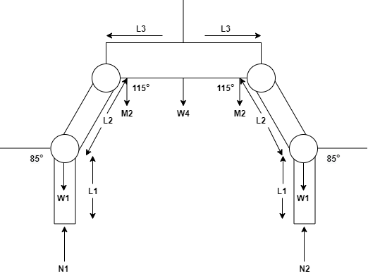
FuzzyBear will be represented by a free body diagram in Figure 1 and will be used as a reference for all subsequent calculations. FuzzyBear is supported by 4 legs, 2 at the back and 2 at the front, with the front set of legs supporting more weight because the robot’s head is heavier than its tail. Therefore, the force in newtons on the front legs, N2, is much stronger at 2.038 N. The tail has less weight and the force in newtons for the hind legs, N1, is lower at 1.872 N. The the various lengths of each femur, tibia, and half part of the body are considered equal on both sides. The length of the femur is L1 at 6.9 cm, the tibia is L2 at 5.7 cm, and the body is L3 at 4.8 cm. The weight for each actuator for W1, W2, and W3 are assumed to be almost the same at 0.0128 kg. M2 represents both W2 and W3. The weight at the center of mass is W4 at 0.371 kg. The angle at the knee, Θ1, is 85° and the angle at the hip, Θ2, is 115°.
From the free body diagram, we can derive the torque at a foot, knee, and hip. First we the found values above to find the torque at the leg, Tleg or T1, in the following equation.
When inserting the given values, we get a value for the leg torque of T1 at 1.24 kg-cm. Using the torque from the leg we derive another equation for the torque at the knee, Tknee or T2, using the following equation.
When inserting the given values and value for T1, we get a value for the knee torque of T2 at 2.02 kg-cm. Using the torque from the knee we derive another equation for the torque at the hip joint, Thip or T3, using the following equation.
Finally, when inserting the given values and value for T2, we get a value for the hip torque of T3 at 2.52 kg-cm.
Conclusion
FuzzyBear will have various inconsistencies for each joint because all parts are not completely identical. Some printed parts might have similar masses and weights, but only to a certain degree. This study focused on the general torque required for joints of the same nature, rather than each specific joint. What we are trying to look for is if the MG90 servos we selected have a rated torque that is suitable for the torques of FuzzyBear.
In Figure 5, we have have the rated torque the MG90s that we will be using. As we can see the rated torque can range between 2.2 kg cm and 2.5 kg cm for 4.8 V and 6V, respectively. The MG90 servos are located at the knee and hip joints. The torque at the knee and hip are 2.02 and 2.52 kg cm, respectively. As the power supply we are using is unregulated between 4V and 6V, the torque will vary between the less than the 2.2 kg cm and enough for 2.5 kg cm of torque. Overall, the selection of the MG90 servos are the ideal selection for FuzzyBear.


