Spring 2016 3D SMD: Origins and Scaling
By Henry Nguyen (Electronics and Control) and Christine Vu (Missions, Systems, and Tests)
Table of Contents
Introduction
In order for us to accurately pick and place components on our pick and place machine, we must be able to identify our origins. Once finding our origins, we will be able have proper Gcode location coordinates on our machine. After finding out (0,0) location for (X,Y), we will be able to accept an Eagle board file as long as the PCB starts its origin at the bottom left corner. Scaling our machine is another important factor that we must address because our machine needs to accurately go to a location based off the Torigins layer from a PCB.
Origins
For our origins, we will begin by hitting out negative X and negative Y limiting switch. From there, we will use our GUI to move our machine X+ and Y+ which coordinates to Gcode values X10 and Y10. This will be our bottom left corner for our PCB. From here we can place our clamping system.
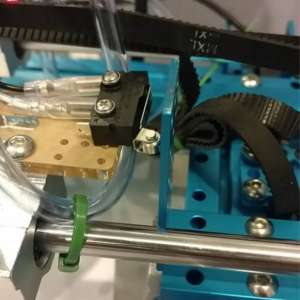
Figure 1. Hitting our X Limiting Switch
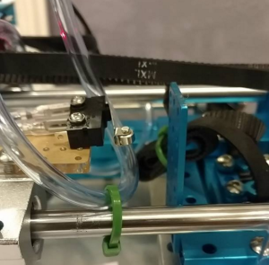
Figure 2. Releasing our X Limiting Switch
In Figure 1, I moved our machine until it pressed our limit switch. This is the maximum our machine is allowed to go in the negative X direction. Next, I will hit out negative Y limit switch. From here, I will move our machine to the positive X and positive Y direction using Gcode coordinates X10 and Y10 as shown in the title picture. This will ensure that our machine will be at the same location every time. We have successfully defined our origin. From here we can place our clamping system.
Scaling
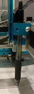
Figure 3. Pen attachment
According to our Gcode, if we have a Gcode input of X100, it should move our machine 100mm in the positive X direction. In order to test if we truly get 100mm for X100, I attached a pen to our Z-Axis and made it mark location X0 and X100 (Pen attachment shown in Figure 3).
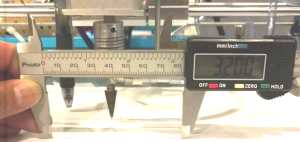
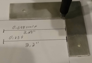
Figure 4. Measurement After Scaling
Next, I measured the distance between the two using calipers with 0.001 tolerance. Previously with our old stepper motors, when running at 1/8th step, our machine was able to draw exactly 4”x3.2” PCB when given an Eagle to DXF to Gcode file. However, when I changed our Me Stepper Driver to 1/16th step in order to preserve accuracy, the pen drew a 2”x1.6” PCB. This gave me an idea that we should double our Gcode coordinates at 1/16th step.
Now that we have 5:1 geared stepper motors for our X and Y Axis, we are able to full step our stepper motors while preserving the accuracy we need. When testing our 5:1 gear stepper motors, I found that we are able to step our machine fairly accurately at full step. In order to preserve speed we will be running our tests at full step; however, if we find that it is not accurate enough, we will adjust our Gcode to take half steps.
Because our maximum PCB size, we will be working with is a 4”x3.2”, multiplying by 25.4 will give us the size the Gcode size in millimeters which is 101.6mm x 81.28mm. When measuring the distance for 3.2inches, I found the scaling factor to be 0.654. Therefore, when I input (81.28 x 0.654 = 53.157), X53.157 will give me exactly 3.2 inches. As a result, we will be using a scaling program to scale our X an Y axis by 0.654 in order to accurately place our 0402 components at the correct locations.
Figure 5.
Shows that at a scaling of 0.654, our machine was able to draw exactly 3.2 inches. The clamping system shows where our origin should be located (If it was draw by the pen which will be placed at the proper location for our nozzle’s true origin.
Conclusion
Overall, we were able to find our origins for our machine. This is a great breakthrough considering that every PCB, reel feeder components, and IC tray will be dependent on this location. Now we are able to place our reel feeder and IC tray anywhere on our machine as long as we gather the proper Gcode coordinates for it. We were also able to scale our motors to accurately go a certain distance that we want using a scaling factor of 0.654. Now when we receive an Eagle to DXF to Gcode file, we will be given Gcode coordinates that we can scale for our machine to accurately pick and place SMD components.

