Spring 2016 Pathfinder Design and Manufacturing – Tilt System Finalized Design
by:
Lindsay Levanas (Design and Manufacturing)
Table of Contents
Introduction
As previously detailed in the Spring 2016 Pathfinder Design and Manufacturing – Tilt System Design blog post, the tilt system will contain a base that will hold the tablet, phone, and tilt servo.1 While a prototype of this base has already been designed, it was around the measurements of the pan servo as the tilt servo had not yet been acquired. This report will serve to document the new tilt system base as designed around the measurements of the new tilt servo. Also mentioned will be the addition of cord holes in the previous design. Note that the final product will be constructed of 3D printed, ABS plastic parts.
Google Tango Tablet Encasement Improvement
In view of one of Pathfinder’s Level 1 requirements, an enclosed environment for a Google Tango tablet was designed.2 However, this design did not take into account the fact that the tablet will need to be continuously charging, as it has a shorter battery life then our Project’s required duration.3 Therefore, the position of the charging port was documented, and a cut-out was added to the previously designed tablet box.
Tilt Servo Measurement Process
In order to redesign the tilt system for the new servo, the servo first had to be measured and modeled. To begin with, the tilt servo’s basic dimensions (height, width and depth) were measured. Below illustrates the depth measurement as an example.
Note that with the servo horn, the depth is 1.744in (illustrated below), and with the fan attachment, it is 1.881in.
Similarily, multiple height and width measurements were taken as needed from varing reference points.
Next, the diameter of the servo horn was measured and found to be .236in.
The placement of the servo horn was based on the midpoint of the circle it is located on. Note that this circle has the same diameter as the width of the servo.
To assist in the tilt servo mounting design, the position of the screw flaps were also measured. These included the distance from the edge of the screw flaps to the other side of the screw holes, the thickness of the screw flaps (illustrated below) and the distance of the screw flaps from the back of the servo.
Lastly, the position of the power and controlling cord was documented to allow for a cord hole to be added to the previous design.
Following a similar process to the one demonstrated above, combined with a few calculations where needed, the servo fan was dimensioned as well.
Completed Tilt Servo and Fan 3D Model
For size and position reference, the above parts were modeled in Solidworks.
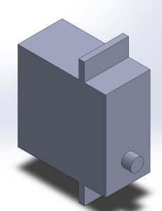
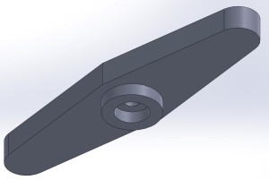
Tilt Servo Base Measurement Process
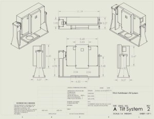
Combining the modeling process of the tilt servo detailed above, with the previous design of the tilt system base1 the previous base was modified to accommodate the new tilt servo. While a variety of measurement calculations were performed, only the main few will be detailed below.
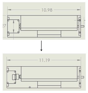
To start with the tilt servo’s total depth of 1.881in meant that the tilt system base width changed from its original width of 10.98in to 11.19in.
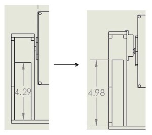
The position of the servo horn changed the height of the servo encasement box supports from 4.29in to 4.98in.
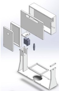
To allow for proper mounting of the tilt servo, the original base design was modified to give room for the servo’s mounting screws. This was done by thinning the front of the servo support strut and servo encasement lid in alignment of the servo’s mounting flaps, as dimensioned above, so that screw holes can be drilled there later.
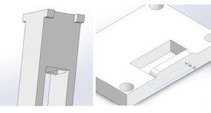
Next the position of the tilt servo’s cord was noted and a hole was added to the bottom of the servo encasement box.
Note that in view of the final selection of LED headlights,4 the previous tilt system base’s headlight holder design was removed. A safe adhesive method will be used for the future design.
Lastly, to accommodate the size of the 3D printer Spring 2016’s Pathfinder will be using, the design of the tilt system base was cut in half and a square connector bracket was added to connect the two pieces.
Conclusion and Future Plans
In conclusion, Spring 2016 Pathfinder’s new tilt system has been modified to fit the new tilt servo and to account for charging cords that are required by components of the system. LED mounting will be detailed after the new tilt system has been fabricated.
Sources:
- Spring 2016 Pathfinder Design and Manufacturing – Tilt System Design, Tilt Base, 3/9/16 http://arxterra.com/pathfinder-design-and-manufacturing-tilt-system-design/
- Spring 2016 Pathfinder Preliminary Design Documentation, Level 1 Requirement, 2/19/16 http://arxterra.com/spring-2016-pathfinder-preliminary-design-documentation/
- Spring 2016 Pathfinder: Project Tango Preliminary Research http://arxterra.com/spring-2016-pathfinder-project-tango-preliminary-research/
- Spring 2016 Pathfinder: LED Headlights http://arxterra.com/spring-2016-pathfinder-led-headlights/


