Dragonbot/Spring/2021
LDC Sensor Testing
Author: Muath Almandhari
Table of Contents
Introduction
As we understood the hardware and the software algorithms that will be implemented to Dragonbot, it was necessary to verify and test the solution before it is being used for the mission. This research will present the steps that were taken to test the hardware and software of LDC sensors.
Hardware Parts
Since one of the LDC1612 features that it supports Arduino IDE, I was able to perform some testing on it using Arduino UNO. Therefore, here is a list of the equipment used in this test.
- Arduino UNO.
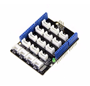
- LDC1612 Grove Base Shield.
- LDC1621 sensor.
- Copper Tape.
LDC1216 Grove Base Shield is a shield that provides a simple way to connect LDC1612 to Arduino UNO. Its main features that it supports Arduino, support I2C standard protocol and handles 3.3V to 5V.
Another important feature of LDC1612 is that it can handle two antennas’ channels connected to it. Therefore, it gave me more flexibility on LDC front shield design and reduced the number of LDC ICs required for it.
Hardware One Channel Connection
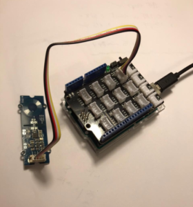
First, I tested the main channel only by connecting the LDC1612 to the Grove Base Shield and connecting the base shield to Arduino Uno. Then I soldered one of the antenna coils to channel 0 of the LDC. Finally, I tested the readings of the LDC using by placing copper tape on the ground tested the sensitivity of the LDC by recording the output from different distances.
Hardware Two Channels Connection
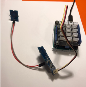
Second, I tested the LDCs reading using both of the channels using the similar connections to the first test. The only difference was that I connected the first antenna to Channel 0 and the second antenna to channel 1
Software program
As for the programming part, in order to control the channels of the LDC sensors was very simple which is by only setting the desired senor configuration to the program. Therefore, I was able to perform tests on both one channel and two channels LDC sensors and observe the reading differences between them
One Channel Connection Software
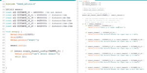
For this test, I used a demo code that is provided with the library of the LDC1612 which detects the distance of any conductive objects around. The code here is using channel 0 as which is the default and pre-connected channel of the LDC sensor. This example is going to test the distance of any conductive object from the LDC sensor. Therefore, a defined range of LDC readings are set for each distance and outputs the distance of the conductive object to the corresponding range.
Two Channels Connection Software
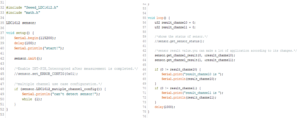
For this test, I used the first channel program in order and applied it for both channels; however, I used multi-channel configuration command in order to give the program access to the second channel. This program will output raw data of the LDC readings for both of the channels.
Output Data Analysis
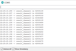
After testing preforming these tests, I realized that the output of the main channel was a little bit less accurate than the second channel because it detects its own components. In addition, I was also able to get the raw output of the LDC1612 which was in form of 8 numbers that increases as the copper tape gets closer to the LDC as shown in the image below. Therefore, I used this output in order to control the distance that is desired to be read for Dragonbot by recording the raw output for the distance between 0cm to 3cm which was between 4369000 and 4400000.
LDC Angle Sensing Test.
Furthermore, I tried to place the LDC above the copper tape at different angles and I realized that LDC1612 gives the most accurate readings in an angle range between 90 degrees and around 80 degrees with respect to the coils. However, the wider the angle gets the less accurate the reading gets until it stops readings when the LDC is facing at about 70 degrees from the copper tape. Furthermore, the placing of the LDC also affects the accuracy of the LDC readings where the LDC loses its accuracy once it gets moved away from the copper tape.
LDC Testing while in motion
The goal of this test is to create a simulation of the robot while it is moving in order to test the accuracy of the LDC readings while Dragonbot is moving in the maze. Therefore, I placed copper tape on a wooden table and moved the LDC in different accelerations at the same distance from the copper tape, and recorded the output of the LDC. The LDC output readings remained the same with the different accelerations as long as there is a copper tape below as well as the same distance from it.
Conclusion
Testing the LDC sensors gave me a better understanding of how the LDC sensors work. I learned how to get the most accurate reading in terms of sensors placing above the copper tape. I was also able to understand how the output of the LDC work which will help me to control the LDC readings for the desired distances only. Finally, it also helped me learn how to program the LDCs to control either one or two channels for one LDC IC at the same time.
References/Resources

