DragonBot Maze Project
Author/s: Matthew Hillsman (PM/CRE), Muath Almandhari (NE), Amha Aberra (CE), Charlie Alfaro (GSE)
Table of Contents
Executive Summary
A fun little game where a robot will navigate on its own through a dangerous labyrinth and find weapons to fight monsters, locate hidden treasure, and escape without harm. The Paperbot maze project is all this, and what better character is there to partake on such a quest other than a dragon? The DragonBot Maze project will utilize LDC sensor to navigate the walls and an RFID sensor to accurately detect the dangerous monsters that wish it harm.
Program and Project Objectives
Project Objectives
The objective for the Paperbot maze project is to design a robot that can navigate the forest maze autonomously. The robot will also need to collect weapons in order to fight the monsters which are located throughout the maze and are guarding the treasure. The robot needed to be designed on the Paperbot chassis. Before the robot would navigate the maze, the robot needs to go over the entire maze and map out the location of all the walls, weapons, monsters, and treasure in every room of the maze. After this initial mapping phase is completed, the robot will be placed in a random location within the maze, and it then needs to be able to figure out where it is located in the maze, and then look at its stored data to form a path to the valuable items, weapons needed to kill the monsters, and then the exit of the maze. In addition to participating in the described maze game, the robot also needed to be self-balancing on two wheels.
The DragonBot is designed with LDC sensors that are used to detect copper on the flat walls of the maze. The LDC sensors will be used to give the robot the ability to stay on the path and to detect the walls that must be avoided.
The DragonBot also utilizes its RFID sensor to detect the playing cards on the maze. The RFID Cards can be used to store unique data for each card on the maze. This will give the robot not only the ability to identify the general card type quickly and accurately, but it will also give the robot the unique advantage to be able to identify the specific card using its unique ID, which it can then store and later recall for the purpose of locating itself during the calibration phase.
In addition to the sensors mentioned, the DragonBot will also contain an IMU sensor and a compass. The IMU will give the robot the needed feedback in order to correct its balance and prevent the robot from falling over. The compass will be used to provide the robot with its orientation so that it can identify which direction it is traveling on in the maze, and to provide a way to turn the robot.
Project Features
The features of the DragonBot robot Project are detailed below:
- DragonBot utilizes the Paperbot chassis which is an inexpensive chassis option for the maze robot.
- The DragonBot contains a custom LDC sensor shield which it can use for detecting walls and barriers and correcting it’s paths so that it stays on track and on mission.
- The DragonBot utilizes a custom RFID shield which provides fast and accurate card detection which can be used for any game set in the paperbot maze.
- The RFID cards can store up to 1Kb of data, allowing the a vast array of possibilities as to what the sensor can be used for, and what data can be stored to make the game more interesting.
- The DragonBot contains an gyroscope which can be used to provide the needed feedback to the robot so that it can correct its balance, and not fall over.
- The DragonBot had a compass, allowing it to detect the direction it is looking, and make needed adjustments to its course and to provide accurate turning data.
Requirements
During the design of the DragonBot Maze project, certain requirements needed to be followed for the success of the design
Engineering Standards and Constraints
Applicable Engineering Standards
- IEEE 29148-2018– ISO/IEC/IEEE Approved Draft International Standard – Systems and Software Engineering — Life Cycle Processes –Requirements Engineering.
- C++ standard (ISO/IEC 14882:1998)
- Federal Communications Commission (FCC)Relevant standards for a product implementing a 2.4GHz radio, FCC Intentional Radiators (Radio) Part 15C, and Unintentional Radiators FCC Part 15B for CPU, memories etc.
- NXP Semiconductor, UM10204, I2C-bus specification and user manual.
- ATmega16U4/ATmega32U4, 8-bit Microcontroller with 16/32K bytes of ISP Flash and USB Controller datasheet section datasheet, Section 18, USART.
- USB 2.0 Specification released on April 27, 2000, zip
- Motorola’s SPIBlock Guide V03.06
Environmental, Health, and Safety (EH&S) Standards
- CSULB COE Lab Safety
- CSULB Environmental Health & Safety
- IEEE National Electrical Safety Code
- Lithium (Li-ion, Li-polymer) batteries shall be stored in fire and explosion proof bag when not in use.
Project Level 1 Functional Requirements
- L1.101 The robot shall autonomously navigate the maze.
- L1.102 The robot should complete the mission in the shortest period of time.
- L1.103 The robot shall enter and exit the maze at the entrance and exit indicated by the Game Master.
- L1.104 The robot shall traverse the maze without passing over any boundaries or impacting any physical walls.
- L1.105 The robot shall find the key before exiting the Paperbot (i.e., standard) maze.
- L1.106 The software program shall not utilize a predefined list of instructions, contained in code, data table, or other data structures to execute a series of hardware actions to achieve the mission objective.
- L1.107 The robot shall be able to make 90 and 180 degree turns.
- L1.108 The robot shall detect when it enters a new room. This requirement can be met concurrent with other maze traversal requirements (see Figures 1 and 2)
- L1.109 The robot shall detect the walls (i.e., hedges) of the room it is currently in.
- L1.110 The Paperbot maze will have a grid spacing (i.e., dimension of a square) of 2.861’’ x 2.861’’
- L1.111 Each room in the Paperbot maze will have a minimum distance of 2.25” from one black line to the opposite.
- L1.112 Thickness of black lines will have a width of 8 pts (2.82 mm or 8/72”).
- L1.113 The robot will be built using the provided wooden-chassis in Humans for Robots 3DoT robot kit.
- L1.114 The key card will be placed in the center of a room in the maze. The Game Master will specify the location of the card, concurrent with the definition of the entrance and exit from the maze (reference L1-103).
Constraints
- L1.201 All robots shall contain one or more custom designed 3DoT shields.
- L1.202 Assembly and basic functional testing of the robot shall be constrained to less than 20 minutes.
- L1.203 each team member will construct their own 3DoT robot. The cost of each completed robot will not exceed $250
- L1.204 Team member robots will be completed by the date of the mission (5/12/21).
- L1.205 The mass of the robot will not exceed 300 grams.
- L1.206 Power to the robots will be provided by the 3.7V Li-Ion battery included with the 3DoT board, with a capacity of 700 mAh (min) to 750 mAh (max) and a power rating of 2.59 (min) – 2.775Wh (max) (included with the 3DoT board). Use of an external battery will use a 2.0mm PH series JST connector located on the 3DoT board and covered in a separate requirement.
- L1.207 All Safety regulations as defined in Section 4.3 Hazards and Failure Analysis will apply to the shipping, handling, storage, and disposal of LiPo batteries.
- L1.208 The diameter of power-carrying wires will follow the American Wire Gauge (AWG) standard
- L1.209 Software will be written in the Arduino De facto Standard scripting language and/or using the GCC C++ programming language, which is implements the ISO C++ standard (ISO/IEC 14882:1998) published in 1998, and the 2011 and 2014 revisions
- L1.210 The assembled robot chassis dimensional envelope will not exceed 6″ width, 8″ height, and 5″ length.
- L1.211 The robot will use the 3DoT v9.05 or later series of boards to achieve the mission objective.
System/Subsystem/Specifications Level 2 Requirements
- L2.1 The custom top shield of the robot will contain an MFRC522 IC which is an RFID sensor.
- L2.2 The RFID sensor shall be used to detect RFID tags and read the data on them.
- L2.3 The robot will have an MPU-9250 IC located on the custom top shield PCB, which the robot can use as an IMU and a compass.
- L2.4 The robot shall use the MPU-9250 as a compass to give the robot the ability to determine its orientation relative to north.
- L2.5 The robot will have an LDC1612 IC located on the custom front shield.
- L2.6 The robot will have 3 antennas coming from the LDC1612 circuit, which are mounted to the left and right side, as well as the front of the robot.
- L2.7 The LDC antennas mounted on the robot shall be used to detect copper tape top the left, right, and front of the robot.
- L2.8 There shall be copper tape placed on every wall in the maze, except where there is a bridge, such that the walls are completely covered with copper.
- L2.9 There will be an RFID tag placed on every card, aside from bridges.
- L2.10 The RFID tags shall have a single byte written to it, which describes the card type.
- L2.11 The robot shall store the wall information it has collected using the LDC sensors in the north, east, west, south configuration based on its orientation reading from the IMU’s compass to be later used during the execution phase.
- L2.12 The robot shall stay on the path by detecting copper tape on the left and right using the LDC sensors.
- L2.13 The robot shall not drive over copper tape that it has detected in front of it using it’s front LDC sensor.
- L2.14 The robot shall take the reading from the MPU-9250’s compass in order to control the angle during the turning of the robot.
- L2.15 The robot should be able to solve the maze in under 5 minutes.
Allocated Requirements / System Resource Reports
After defining all the High-level requirements of Dragonbot, the next step is to define the Low-level functions of Dragonbot. The following allocated requirements will translate the functional and performance design criteria such as the mass of the components used for the design as well as the power used.
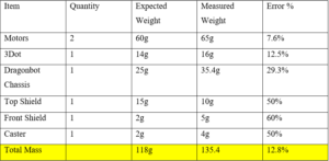
The weights of the components were measured by using a scale. This was done by measuring every all Dragonbot’s parts individually and the Drogonbot as a whole. The table below shows the expected and the measured weights of the materials that were used on Dragonbot’s construction design. It also provides the expected and measured total mass of Dragonbot after the completed construction. The external parts which were used to provide stability to Dragonbot’s movement were the larges in mass comparing it to the other objects. On the other hand, the top and front shield were designed to have small dimensions in order to reduce the size and mass of them. although the expected and the measured mass reading of the individual components had some errors, the total mass of the Dragonbot had a small percentage of error which allowed us to go as for the expected plans of design.
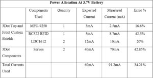
The power allocation was measured by testing each of the Dragonbot’s components individually while having the same power source of 3.3V. Initially, we started off by giving and estimations for the amount of current used by each of the components. For the next step, we measured the currents of the components using a multimeter in order to measure the maximum power used for the Dragonbot. Due to the “stay at home” orders for COVID-19, we were not been able to use the school tools to measure these parameters. Therefore, the measurements might have a percentage of error. In the table below, you can navigate the current and the power for each one of the components used for Dragonbot.
Project Report
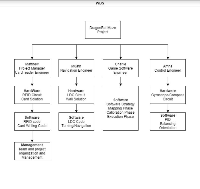
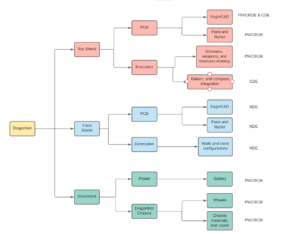
In order to get Dragonbot designed and constructed with the most efficiency and construction criteria, it was important to breakdown the project into different segments and each team member must and engineer must complete their sub-segments to provide a whole project. Therefore, here is team Dragonbot’s work breakdown structure (WBS) and product breakdown structure(PBS) that was adopted throughout the project design.
Project WBS and PBS
Team DragonBot’s Work Breakdown Structure attempts to divide the work load of the project among the team members as evenly as possible.
Matthew assumed the role of Project Manager became in charge of the management of the project and the organization and work management of the team. Matthew also took on the role of the Card Reader Engineer and became responsible for the design and implementation of all hardware and software associated with the robots ability to read and interpret the cards on the maze.
Muath took on the role as the team’s Navigation system engineer and became responsible for designing the hardware and software solution for the robot’s ability to read wall information and navigate the maze.
Charlie took on the responsibilities of the Game Software Engineer, and he became responsible for all software related to the robots decision making and ability to successfully play the maze game.
Amha became the team’s control engineer, and became responsible for designing the hardware and software associated with the robot’s ability to self balance itself, as well as to give the robot the ability to find its direction.
Dragonbot’s product structure can be divided into three main segments which are: the top shield, the front shield, and Dragonbot’s chassis. The top and front shield can also be segmented into multiple products including the type and the number of the sensors used, as well as, the components used for the shield. It also includes PCB board manufacturing along with soldering.
The top shield includes one RFID sensor whose antenna will be sticking out of the Dragonbot chassis to read the cards. In addition, it will include an IMU to provide control of the Dragonbot balance and to provide it with information about its orientation. On the other hand, the front shield will include two LDC sensors which are used to read the configurations of the room and navigate Dragonbot throughout the maze. Finally, movement will only include the 3Dot motors and the Dragonbot chassis.
The product breakdown structure was divided between the team members as the following:
PM/CRDE = Matthew (Project Manager/Card Reader Design Engineer)
NDE = Muath (Navigation Desing Engineer)
CDE = Amha (Control Desing Engineer)
Cost
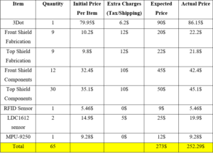
The table below shows all the components purchased for the project. The table includes the price of the 3Dot as well as the price of the breakout boards of the sensors used for testing. In addition, it includes the price of the PCB board fabrications as well as the components that were to construct them. The table also shows the extra payments included with the price for instance taxes and shipping price. As the table is showing, Dragonbot’s total components price was 252.29$ which did not exceed the limit price that was put initially of 255$.
Schedule
The work schedule for team DragonBot was needed in order to keep the team organized and on track throughout the course of the semester. The work timeline for team DragonBot can be seen in the image below.
Concept and Preliminary Design
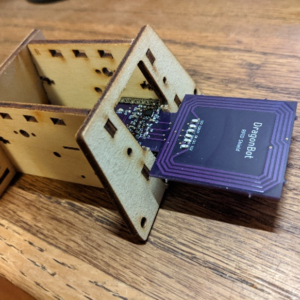
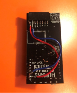
For this project, the conceptual and design differ given adjustments of the shield, initially, the team considered that the RFID sensor for card reading and copper tape sensor would be at the same level of the chassis, and the readings were going to be done directly on the spot where the robot was standing. However, the practical RFID sensor that was used, had to be adapted for the rear pinout of the 3DotBoard and consequently, the antenna was in front of the chassis, also, the pins from the 3DotBoard were rewired so it could be adapted to the copper sensors, which were glued to the sides of the chassis as well as the front back.
Literature Review
The Primary aspect of research that went into this project, where the solutions surrounding the card reading and detection, the wall detection and path following, the balancing, and the overall game software.
The research of the card reading and detection was concluded when the RFID sensor was selected as the sensor of choice, as it provides accurate readings from a reasonable range, and it can preform those readings quickly.
The research that went into the wall detection was concluded with deciding on LDC sensor as it has a low profile on the maze, and is a reasonable choice for detecting and following lines.
The research on the balancing of the robot was concluded with the decision to use an IMU sensor.
System Design / Final Design and Results
The sensor solution chosen for reading the game cards that will be placed throughout the maze is to use an RFID sensor. RFID uses a sensor module with an antenna to get a unique ID as well as any other information that has been written to a passive (non-powered) device referred to as an RFID tag. The sensor module generates a high frequency electromagnetic field. When the antenna of the module passes within close proximity of an RFID tag, the EMF powers up the passive component which then responds with an identification number and data that has been written to the device. The information that the tag responds with can then be used by the software to identify the card type.
The purpose is to build an autonomous guided robot which must be able to navigate through the maze and detect without a physical track. Therefore, the navigation solution chosen for this mission is using LDC (induction to digital converter) sensors and a conductive wire embedded under the maze. The mechanism of an inductive guided robot is simply by making the robot detect the direction of the conduction reflected to the sensors to identify its path. The working principle of a LDC sensor is by detecting the inductions cause by the magnetic field from the conductor. Then it will measure the parameters of the LC oscillator formed by the PCB copper trace and the capacitor.
The purpose of the sensor is to detect tilt and/or whether the robot is falling forward or backward. I started my research on arxterrea.com to find balancing wheel projects but I couldn’t find any on that site. Then I began looking for a self-balancing project on other sites. I have found many (Arduino) DIY self-balancing projects. I researched different types of tilt sensors, and I found that there are three types of sensors – Accelerometer, Gyroscope and Inertia Measurement Unit (IMU). Accelerometers are used to sense static and dynamic acceleration; they are used for tilt-sensing. Accelerometers tell how it’s oriented with respect to the Earth’s surface. Gyroscopes measure angular velocity, how fast something is spinning about an axis. Gyros are not affected by gravity. IMU combines both accelerometers and gyroscope sensors and are used in many Arduino projects. Among the IMU sensors, I learned that MPU 6050 sensors are mostly used. I decided to use the MPU 6050 sensor because it has been widely used in Arduino projects, there are plenty of resources online, and it is reasonably priced and it fulfils the requirements.
The purpose of the game software engineer is to develop an algorithm that would explore the maze during the mapping phase. Also, to incorporate the sensor input from the other teammates to an algorithm that would accomplish specific objectives defined on the “Rules of the game” documents starting from random positions after the mapping and calibration phase. Integrate the information to find an optimal path solution. Occupancy grid mapping is a set of algorithms designed to represent a map of the environment into spaced binary random variables, where the presence of an obstacle would be detected by the sensor and translated by the algorithm as a value within a grid of variables.
System Block Diagram
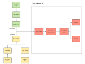
Below is the system block diagram of Dragonbot. This block diagram shows the system and the subsystems that Dragonbot’s functionality design is based on. It shows how every function is responsible for a specific mission and it details how every part is being controlled and where it is located in the project. On the left side, it shows the top and the front PCB board shields which will contain the LDC1612 sensors, the RFID sensor, and the compass. The 3Dot will connect these two shields through its front and top connector headers in order to get receive their readings and send it it to the microcontroller which will control the movement drive system. The PCB Custom boards will communicate with the 3Dot board using the I2C serial communication via SDA and SCL Pins. The subsystems front and the top shields are divided as the following. The LDC1612 sensors on the front shield are responsible to control Dragonbot’s movement and getting the room configurations. On the other hand, the RFID and the IMU sensors are responsible to send information to the microcontroller about the weapons, treasures, and monsters, as well as getting the orientation of the 3Dot to control the turning functions.
Interface Definition
Modeling/Experimental Results
LDC Sensor Testing:
As we understood the hardware and the software algorithms that will be implemented to Dragonbot, it was necessary to verify and test the functionality of the solutions in this mission. Since one of the LDC1612 features is that it supports Arduino IDE, we were able to perform some testing on it using Arduino UNO and Grove Base Shield as well as the 3Dot board. Furthermore, another major feature of the LDC1612 is that it can support two antenna channels at the same time; therefore, the testing and readings that were recorded were based on single and multi-channel testings.
LDC sensor testing was focused on two different segments which are: testing the LDC angle sensitivity and testing the LDC sensitivity while motioning. These two tests will allow us to get a better understanding of the LDC readings’ behavior in similar settings to what they will be in while the demonstration.
1. LDC Angle Sensing Test: For this test, we placed the LDC above a copper tape at different angles and recorded the output behavior while varying the angle between 90 degrees as the LDC is facing the copper tape and 180 degrees as the LDC is facing away from the copper tape. We noticed that the wider the angle gets the less accurate the reading gets until it stops readings when the LDC is facing at about 70 degrees from the copper tape. In addition, we noticed that the placing of the LDC also affects the accuracy of the LDC readings where the LDC loses its accuracy once it gets moved away from the copper tape.
2. LDC Testing while in motion: The goal of this test is to create a simulation of the robot while it is moving in order to test the accuracy of the LDC readings while Dragonbot is moving in the maze. Therefore, we place copper tape on the maze and moved the LDC in different accelerations with the same distance from the copper tape, and recorded the output of the LDC. The LDC output readings remained the same with the different accelerations as long as the LDC angle and distance from the copper tape remained the same.
LDC Sensor Output and Data Analysis
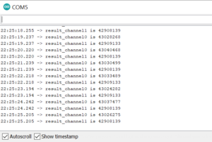
After performing many iterations of tests, we realized that the output of the main channel was a little bit less accurate than the second channel because it detects its own components. As a result, we decided to an external antenna for both of the channels to get the most accurate and efficient readings from both the channels. In addition, we were also able to get the raw output of the LDC1612 which was in form of 8 numbers that increases as the copper tape gets closer to the LDC as shown in the image below. Analyzing the raw data output of the LDC helped us on controlling the sensitivity ranges of the LDC to the desired distances that fit with Dragonbot’s design.
MPU 9250 Sensor Testing
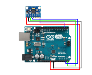
The 3Dot robot comes with two wheels and a caster (to keep it balanced). Without the caster, either the front or back frame will touch the ground. In order to keep the robot balanced on two wheels without the caster, it needs a mechanism to detect the tilt and move in the direction to which it is tilting to balance itself. The information about the tilt can be obtained from the Inertia Measurement Unit (IMU). Therefore, for this test MPU 9250 sensor is used to sense the tilt angle. There are many Arduino library files for MPU 9250. However, After exploring several of the available library files for the sensor, we decided to use the “MPU9250_WE.h” library file because it provides the orientation in degrees which makes it easy to work without going through the process of converting the raw data. In order to get an accurate reading, the sensor needed to be on a stable surface. Thus, we mounted the sensor on a block of wood; that way, we can easily maneuver the sensor and observe the changes. The MPU9250 breakout board was connected to Arduino Uno board, as shown in the diagram below:
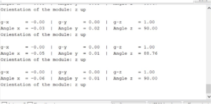
The sensor was moved in all 6 directions (up/down, front/back, and side to side) and rotated clockwise and counterclockwise along the 3 axes (x, y, and z) to observe the changes. For this experiment, the front is determined to be +x direction and the upward is +z direction. When the block is at level (at rest), the x-axis and y-axis are zero and the z-axis is 90 degrees. On the serial monitor, it was observed that when the sensor is tilted forward-tilted and/or suddenly moved, the reading from the x-axis is negative and when tilted backward tilted and/or suddenly moved it becomes positive; on contrary, the z-axis does not change a sign but the reading on the z-axis decreases to less than 90 degrees when tilting forward or backward. To determine the direction of the tilt angle, combining acceleration values along x and z axes are needed. The tilt angle (accAngle) is determined by the atan2 (x, z) function.
It was noted that the gyroscope reading changes when there is a sudden tilt about the respective axis. To get a better measurement of the changes in the angle, it is important to combine the measurements of the angle from the accelerometer and gyroscope by using a complementary filter as shown in the equation below:
Angle = (1-α)*(previousAngle + gyroAngle) + α (accAngle)
PID controller test: Initially I tried to control the motor speed directly with the value proportional to the error with no success. Then, after further research, I realized that better motor control can be achieved with a PID controller. The PID controller looks at the set-point (which is 0 degrees) and compares it with the actual value of the tilt angle. If there is an error (tilt angle >0 or < 0), corrective action is needed; this is obtained by detecting the tilt angle and moving in the direction in which it is tilting/falling. The PID algorithm has three parts – Proportional, Integral, and Derivative. The proportional term depends only on the difference between the setpoint and the error. The integral component sums up the error over time, and the derivative response is proportional to the rate of changes of the error. The manual tuning of the PID controller requires trial and error. First, I set the KI and KD to zero and gradually increased the KP until the robot starts to oscillate – if the proportional gain is too little the robot will fall, and if the KP is too large it makes the robot oscillate wildly; a good enough KP makes the robot oscillate a little. Once the KP is set, I adjusted the KI to reduce the oscillation, then I adjusted the KD to improve the response time. The tuning process required multiple iterations (trial and error) to fine-tune each parameter to achieve a better result.
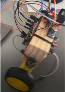
PID Control Code testing: I was testing the code on a robot made from a block of wood (figure 6). Since the wires were exposed, after each test (with every fall) some pins were bent and/or broken. Therefore, I built a larger robot to enclose the wires and the Arduino board inside and continued to test the code. However, After many trials and errors, I was able to balance the robot that I built. Then, I implemented the code on the 3DotBot with some modifications. I followed similar steps to tune the PID control in order to balance the 3DotBot on two wheels.
Testing of RFID
The initial testing of the RFID sensor was performed on a breakout board, which contains the MFRC522 IC, made by Hiletgo. The testing was performed with an Arduino Uno. The Arduino and RFID board were connected via the SPI communication protocol. This test was performed using the SPI rather than the I2C because the breakout board used was hardwired to use only the SPI protocol.
The tests performed on this RFID module included verifying that the sensor would be able to detect the ID of the RFID card, confirming at what range the sensor would be able to read the card consistently and reliably, testing where the card must be and at what angle with respect to the sensor in order to get a proper reading, testing how long the card must be near the sensor in order for a proper reading to take place, and testing the effects on the reading with the card in motion at different speeds.
To test that the sensor was successfully reading the cards, the RFID sensor module was installed into a breadboard. Wires coming from the Arduino Uno were installed into the breadboard in order to connect the sensor to V3.3, GND, the 4 signals required for the SPI communication, and an additional signal that serves as a reset signal.
The card and keyfob included with the HiLetGo breakout board were used to conduct the test. The card was brought near the RFID module’s antenna, while watching the serial monitor. The Serial monitor returned the card ID value along with an “access granted” or “access denied” message. Upon being able to see the ID of the card from the serial monitor, it was concluded that the module is working.
Range and Reliability Testing
Using the same setup described above, the card was then moved further away from the sensor’s antenna, to see at what distance I can get card readings. The card and antenna were separated by distance as I moved the card in front of the antenna. I noticed that the readings were consistent when the card was approximately 3 centimeters or less from the antenna. When the card was moved at a distance greater than 3 centimeters, the readings stopped completely. I was able to conclude from this test that the sensor will give a reliable reading virtually every time the card is 3 cm or less from the sensor. When the distance was greater than 3cm, no readings would take place at all. This test was performed with respect to both the top side and the bottom side of the antenna. The results for both sides of the antenna were identical.
My initial expectations were that the card readings would be reliable at close range, then the reliability of the readings would slowly fade as the distance was increased. This was not the case, as there was no fading effect of the reliability as the distance was increased. The results were that the card was either within range of the sensor, in which the sensor would read the card consistently, or it was out of range, in which the sensor would not read the card at all.
Card positioning and angle testing
Using the same setup as described above, the card was then position so that it was not directly above the antenna, but some distance to the side, but within the range of the antenna that was confirmed above. The results were that no card was read. This was confirmed several times. I then moved the card so that it was orthogonal so the plane containing the antenna coil but touching it on the side. The results were the same, and no card was read. I tried this several times with different positions of the card with respect to the coil, but the results were all the same, no card was read. I was able to conclude from this that the sensor will not read a card that is to the side of the coil, but that the card must be directly above the coil in order for it to get a reading.
I then placed the card so that it was directly above the sensor’s coil, but I tried it with the card not directly parallel with the coil, but at different angles. The results I had found were that the sensor would read the card consistently up to about a 45 degree with respect to the sensor’s coil. Between 45 degrees and 60 degrees, I would get some readings, but less consistently. Between 60 degrees and 90 degrees with respect to the coil, I would get no card readings. These results were identical when tested on both the top and bottom sides of the sensor’s coil.
Length of time to perform a proper reading
The verification test was performed again, but with special attention being made to the length of time required for the sensor to read the card. Upon performing this test, it was quickly realized that the length of time to get a reading was faster than could be accurately measured with a stopwatch. To the human eye, it had appeared that the reading of the card and its data was instantaneous. It was concluded that the length of time needed to get a card reading was so negligible, that it would not interfere with the operations of the robot, and that the length of time would not need to be accounted for as it was essentially instant.
Reading of card while in motion
The final test I performed on the breakout board was testing the reliability of reading the cards while the sensor was in motion. The purpose of this test was to simulate the robot as it is driving through the maze, and to test if this motion needed to be accounted for on the card reading reliability. The card was placed on the desk. I picked up the breadboard that the sensor was attached to, as well as the Arduino, and I began moving the sensor back and forth over the card, while watching for the card readings on the serial monitor. I began by moving the sensor slowly, then gradually increased the speed of the sensor with respect to the stationary card. The results were that the card would be read consistently at all the speeds possible. It wasn’t until the speed of the sensor was significantly more that we would ever be able to get the robot to move, that the sensor began failing to read the card.
Electronic Design
Dragonbot’s electronic design contains two PCB custom boards as top and front shields. The top shield will include an RFID sensor and a gyroscope and will be connected to the top headers of the 3Dot board, whereas the front shield will contain two LDC1612 sensors and will be connected to the front headers of the 3Dot board.
PCB Design
For our LDC sensor design, the aiming goal was to design a shield that will be capable to handle three-antenna channels that will be jump wired to the backside of Dragonbot’s chassis. However, Since the front shield must have size limitations because of the caster, it was important to use as less components as we could for the PCB board. In addition, knowing that each one of the LDC1612 sensors can handle two antenna channels, we decided to use only two LDC1612 sensors for the PCB board which will control the three different antenna channels.
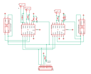
the final iteration of the front shield circuit schematic went through many iterations and revision processes. As the circuit shows below, the LDC1612 sensors use the SDA and SCL pins for the I2C serial communication and powered by a 3,3V power supply. Another important thing to mention is that in order to control each LDC1612 sensor separately, we had to connect the ADDR pin of one of the LDC sensors to GND while the other to 3.3V. This step gave us the ability to assign a specific address to each one of the sensors. Therefore, the right LDC sensor’s ADDR pin is connected to GND which would give it the default address 0x2A. On the other hand, the left LDC sensor’s ADDR pin is connected to 3.3V which would give it an address of 0x2A.
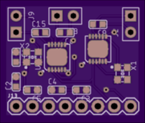
For the final iteration of the LDC front shield PCB design, it was mostly focused on reducing the number of components used and traces as much as possible to decrease the size of the shield. Therefore, after taking upon Professor Hill’s recommendations, we decided to have the top layer as a GND layer while the bottom layer as a 3.3V. Furthermore, the bendings of the traces were made to have a 45-degree angle in order to reduce the traces’ impedances. Finally, by closing up the components as much as possible to the head connector, the dimensions of the shield were 0.75″ * 0.9″.
The first iteration design of this PCB had the antenna very close to the header pins. This would make the PCB impossible to install into the paperbot chassis as the top part is too wide, even if the entire wooden back of the chassis was removed, the PCB would still not be able to fix. This iteration also used 6mil traces for all of the signal lines, while 8mil is the minimum desired trace size. There were also several angle errors with this design, which needed correction.
In the second iteration the problems associated with the first iteration were corrected. The problem with the antenna not being able to fit into the chassis was corrected by extending the antenna so that it is on the outside of the chassis and would be able to fit with minor modification to the wooden back panel. The traces were made larger and the errors with some of the angels were also fixed.
In addition to fixing the above problems with the first iteration, the second iteration of the design also included the IMU circuit which included a gyroscope and a compass, and was intended to give the robot the ability to self-balance itself, as well as be able to give the robot its orientation relative to north. This circuit was designed by team DragonBot’s control engineer. The only problem associated with this design is that since the RFID IC used the SPI communication protocol, there were no additional pins available to use in the event that we needed to use the wheel encoders.
In this final iteration of the RFID PCB design, the MFRC522 IC was changed from using the SPI protocol to using the I2C protocol, so that the additional pins used by the SPI bus could be freed up to use as digital input/output pins if desired. The I2C address needed to be set, and for that the procedure found in the MFRC522 IC’s data was used to set the address.
Firmware
Game Software
To develop a Game software for the paper robot project there were many matters to consider from the general structure of the game software to the implementation of the code for a functional robot.
The maze system logistic
The mission specified on the rules of the games file consisted in a set to steps to be accomplished by the robot, these steps were divided in three main components, Mapping phase, Calibration Phase, and execution phase.
Mapping phase
For the mapping phase the robot would autonomously navigate the maze and record each piece of information, such as the room information and card information, then it would store the information in a multi-dimensional array using hexadecimal values. For this maze we had 14 different room configurations denoted with hexadecimal numbers and letters representing specific binary values, which would describe the internal set of walls and opening for the room.
Mapping sequence
As far as the mapping sequence, we followed a zigzagging pattern to cover each possible room. However, due to the constrains before we were obliged to specify certain steps before an actual linear mapping, such as reading a Card ahead and, obtaining the previous room information to determine if there was a wall or not behind the robot. The checklist for the mapping and sequencing went as follows. (Note that this sequencing only applies to our robot and its constraints).
Calibrating the robot
Calibrating the robot required the team positioning the robot in a random spot in the maze, then the robot would wander the maze and determine its initial position. Fortunately for our team the tags used for the card reading had a specific and unique ID that differentiate them individually. Thus, for the calibration, the game software created two functions, one of them would store the ID with their respective column and row position, and the other one would read the ID and obtain that specific row and column where is stored. That way, the robot roaming the maze would encounter a Card and instantly know its position in the maze.
Switching the mission
When performing the execution mission, the game software engineer was not able to incorporate a path finding function for the rapid solving of the maze, which, was one of the requirements for the missions. As the mission was complex it would have taken too much time for the robot to achieve it manually or at least without a path finding function. Thus, the team agreed on doing a new and simplistic mission, which would not include a mapping nor a calibration phase, but would be exploring the maze, finding a key, and exiting the maze.
Key finding main function.
This function would run while an exit was not found, yet, before finding an exit the robot still would need to recover a key, thus, an if condition would determine if the robot found the key and it would toggle an LED light as well as assigning a number to a variable that would verify a key found and exit that statement. After the key was recovered, the robot would continue to explore the maze and look at each of the rooms and if there were not a valid exit, it would continue to explore (Note: Given that the path finding algorithm could not be implemented for any of the missions, the robot would explore randomly the maze).
Due to constrains in time and copper sensor reading the team was not able to test out the Descoped mission code, however, if the readings and other hardware issues were functioning properly, this is the code that would have completed the descoped mission in exchange of the original mission.
LDC Software
The fundamental objective of this project is to build an autonomous guided robot that will use three LDC sensors placed in the front of the chassis which will detect copper tape placed in the walls of the maze to solve it. The main goal is to make Dragonbot go to every room and get the its walls configurations and send it to the Game Software in order to solve the maze. The first step was creating two separate functions that will get the readings of both of the LDC sensors. Therefore, the first LDC sensor’s function is “LeftAndFront()” which will receive the readings from the left and front sides sensors. This function will return an array of 0s and 1s for the reading of the front and the left sensors respectively. The second LDC sensor’s function is “rightOnly()” which will output the readings of the right side sensor as a 0 or 1 as well.
The next step of the code is to get the room configurations using the readings received from the left, front, and right sensors. Therefore, “NAVIGATION_allSensors()” function will return a hexdecemal integer for the room walls configurations in the sequence of (right, front, and left). Finally, “wallsDirection()” function will take the compass as an input and call “NAVIGATION_allSensors()” in order to get the room configuration and the walls directions based on Dragonbot’s orientations at that moment. The image below shows one case which when Dragonbot is facing north.
IMU Software
The DragonBot will utilize its magnetometer that is on the customized PCB for orientation and turning. The initial orientation that is captured from the magnetometer will be stored as a fixed variable outside the loop for reference. The robot refers the initial position for orientation and to turn left or right.
RFID Software
For the software of the card reading, there were essentially two functions that needed to be developed that would be on the robot, and then there would be a third function that needed to be developed which would be used to write data to the RFID card, before the maze game.
The first function was called getCardData(). If this function was called, it would return 0x00 if there was no card present. If there was a card present, the function would read a specific byte from the stored data of the RFID card, and it would then compare the value of this byte with the values of all valid card types which were saved in an array.
The second function that would be on the robot was the getCardId() function. this function was used to read and then return the unique ID of the RFID card, which was a four byte value. The purpose of this function was so that the robot could call this function during the mapping phase, and it would then store this value into a matrix on the robot’s memory. The robot could then use this data to recall during the calibration phase of the original mission of the maze game, so that the robot would be able to find it’s initial position in the maze upon the very first card that it came across during the calibration phase.
The third function that needed to be developed was the function which was used to write data to the card. This function was in the void loop() of its code because it would not go on the robot, and was run by itself in order to save data to the RFID cards.
Verification & Validation Test Plan
In order to verify that design implementations of Dragonbot meet all the level 1 functional requirements, it was important to set a verification plan for it. Therefore, we decided to divide the verification plan into four main test stages. Each test stage must verify the functionality and the efficiency of that stage’s requirements. Furthermore, each stage must provide details about the test, criteria, and requirements for successful test verification.
Test Stage 1
This stage will verify if Dragonbot meets all the basic operational requirements such as movement functionality. This testing stage is not related to the design mission objective. This testing stage was performed by all Dragonbot team members.
Test Stage 2
At this testing stage, the Dragonbot must verify that it meets the construction design requirements. It must verify that it can be assembled and disassembled easily and antennas are placed where they are planned. This stage is also not related to the mission.
Twst Stage 3
At this testing stage, Dragonbot must prove and verify that it meets all the mission operations requirements. Therefore, Dragonbot must utilize the LDC sensors to get the room configurations, use the RFID sensor to collect weapons and treasure, and use the IMU to control its turning. Then, it should utilize the information observed to execute the maze using the steps that were planned priorly.
Concluding Thoughts and Future Work
This course allowed students to understand some of the applications of software and hardware implementation to automated systems by building and troubleshooting a to be automated maze solving robot. Also, students were able to develop their own solutions for a given mission, by researching and incorporating their own ideas regarding the sensors, shield design, and adapted to a pre-built board with its respective chassis. The development of software and as well as hardware was a key part of the course, outside lectures on the Arduino IDE and Eagle aided students to understand and use some programs used for the structural functionality of the robot. Finally, students learned to work as a team, and aid each other by implementing a collective software development based on an individual hardware development.
References/Resources
These are the starting resource files for the next generation of robots. All documentation shall be uploaded, linked to, and archived in to the Arxterra Google Drive. The “Resource” section includes links to the following material.
- Project Video
- CDR
- PDR (N/A)
- Project Libre (with Excel Burndown file) or Microsoft Project File (N/A)
- Verification and Validation Plan
- Solidworks File (zip folder) Linked to in Mechanical Design Post (N/A)
- Fritzing Files Linked to in Electronics Design Blog Post (N/A)
- EagleCAD files
- Arduino and/or C++ Code
- Other Application Programs (Processing, MatLab, LTSpice, Simulink, etc.) (N/A)
- Complete Bill of Materials (BOM)
- Any other files you generated that you believe would help the next generation of students working on this project.


