Dragonbot/Spring/2021
LDC Sensor Hardware Implementation
Author: Muath Almandhari
Table of Contents
Introduction
In order to make Dragonbot able to identify its path and detect its surroundings, it was necessary to create a proper design solution that would satisfy its needs. The objective of this blog is to present and explain the hardware navigation solution that is implemented for Dragonbot.
Hardware Implementation Research
The goal is to build an autonomous guided robot that must be able to navigate through the maze and detect without a physical track. The purpose of using LDC sensors is simply to make the robot detect the direction of the conduction reflected the sensors to identify its path. Therefore, the LDC sensor will detect the inductions and walls caused by the magnetic field observed from the copper tapes that are placed along the walls of the maze.
LDC Sensor Antenna Placing
The mechanism of navigation that is desired to be implemented on Dragonbot is to have all three LDC sensors evaluate the strength of the signal generated by the copper tape that is placed in the maze’s walls. Initially, we decided to have only two LDC sensors on the right and left sides in order to detect the walls; however, we realized that the room and intersection possibilities require to have a third LDC sensor in the front.
This method will allow Dragonbot to send the room configurations by receiving the readings of the LDC sensors from each side and then send it to the Game Software.
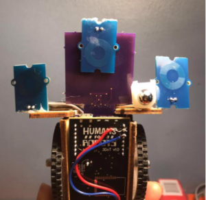
Therefore, after connecting both of the LDC breakout boards to the front shield, I soldered the three channel antennas to them. The right LDC breakout board included only one channel antennas which placed on the right side of the chassis. On the other hand, the left LDC breakout board included two channel antennas which were placed to the front and the left side of the chassis. In order to make sure that the antennas will hold in place, I hot glued them to the chassis on each side as the image shows below.
Copper Tape on the Maze
placing the copper tape went in two main different stages. The first one was to have copper tape only on the walls, the second was to have copper tape on the walls and in the room boundaries.
Copper Tape on the Walls Only
For the first implementation, we had copper tape only on the walls and Dragonbot was supposed to detect only the walls of the path that is around it and in front of it. Each LDC sensor from each side shall return 0 if it did not detect a copper tape or a 1 if it detected a copper tape as the Dragonbot is moving. However, after testing this algorithm, we came to a conclusion that the robot will not be able to differentiate between a room boundary and a wall. Furthermore, due to the movement adjustment of Dragonbot which requires a continuous reading to the walls, the robot kept on getting confused and not able to read a four-way intersection which leads it to stop.
Copper Tape on Walls and Boundaries
Since the Game Software mapping algorithm requires getting room configuration readings, Dragonbot was required to stop and get rooms configurations of the maze individually. In addition, to solve the confusion of the four-way intersection, we had to come up with a different approach than the first one which is to have copper tape in the room boundaries as well.
This mechanism requires having thicker copper tape lines on the wall and thinner copper tape lines in the room boundaries. Then, after performing multiple testing iterations of the LDC sensitivity range, we were able to make the robot recognize when the is a thin wall of copper tape indicating a room boundary and a thick wall of copper tape indicating a wall of the maze.
Hardware Implementations Challenges
One of the main challenges to have a successful LDC navigation solution was to get a precise reading from the LDC sensors. LDC1612 sensors’ sensitivity is very strong and its output changes rapidly for any external interference. Therefore, having the right and the left sensors’ readings in sync was very challenging and required a lot of testing. On the other hand, I realized that the front sensor always loses its reading accuracy due to inertia.
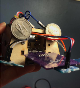
The backward thrust that the chassis observe as the wheels start moving forward leads to make the chassis lean backward a little bit making the front sensor loses its reading. In order to solve the problem, I had to come up with a solution to hold the front side of the robot’s chassis to the ground as it moves forward. Therefore, I placed two coins on the front side of the chassis and in a position that do not have any effects on the LDC readings.
Conclusion
In conclusion, this blog post covered the hardware solutions implemented on the Dragonbot chassis for the antennas placements and the maze as the copper tape placement, as well as, the procedure of implementing these solutions.


