MarioBot Generation 1 Summary Blog Post
Author/s: Denil Poudel., Justin Salvador., Martin Hernandez.
Table of Contents
Executive Summary
Mariobot is a 3D printed kart that can be controlled wirelessly. Inspiration for this project originated from the ModWheels Generation #3 project and has further developed into a design that replicates the MarioKart: Live Home Circuit that is available at many retail stores. This design includes a 3DoT V10/V11 board which will tie all of MarioBot’s features together. First off, MarioBot includes two 12V metal geared motors, an LM3478 Boost Converter that will temporarily increase the speed of the kart, and a FS1B105ZF Super-Capacitor that contributes to the speed increase. In addition, Mario kart will utilize the TCS34725 color sensor for two important features. The first is for the robot to virtually pick up items based on the color of cards on the floor. Mariobot will use these items to interact with the real world. Secondly, it will be used to configure the race track to ensure that no user can simply cheat by going to the end. Furthermore, MarioBot will use the TSAL6100 IR Emitter and TSSP58P38 Digital Remote Receiver in order to “throw” green shell items at other players. With the innovative ArxRobot App, users will have the capability of controlling their MarioBot and participate in two game modes: Multiplayer and Time Attack (Single Player). In multiplayer, users will race against each other to see who’s the better driver. Items are dropped within the race track so that they may have an advantage over their opponents. In Time Attack, a single user will run through the race track to see if they can set the record and become the fastest driver. This race track can be set up at the user’s expense, so the level of difficulty can change in an instant.
Program and Project Objectives
Program Objectives
The Robot Company (TRC) will be attempting to showcase a replica of the Mario Kart Live: Home Circuit. This demonstration will take place on CSULB campus in Long Beach, CA on May 12, 2021. Users will be able to control Mariobot’s steering as they compete against other Mariobots or be able to race against the time to complete the course. In addition, Mariobot will include three items inspired by the Mario Kart Live: Home Circuit game: the mushroom, heart, and green shell. These items will affect the game in different ways.
Project Objectives
MarioBot is designed for the main purpose of racing against other karts. Though the design may be straightforward, there are layers of characteristics that lie within this project. A custom race track can be outlined, communication between other karts, detecting color cards placed on the ground, and a significant increase in speed are the main components of this design. ArxRobot, a bluetooth mobile application, will be essential to this project, providing telemetry communication to the 3DoT board, thus providing movement to the kart.
Mission Profile
The mission is for MarioBot to compete in one race which will take place in a configurable race track. In addition, Mariobot should be able to affect the race with designated items that each have their own unique abilities.
Project Features
- Connectivity with ArxRobot Mobile Application through Bluetooth
- 3DoT V10/11 Board Powered by 3.7V Hixon RCR123A Battery
- 3D Printed Model of Chassis
- 2 Free Spinning Wheels / 2 Wheels for Driving (4 Wheels Total)
- 1 Servo Motor for Steering
- Custom Front Shield for Color / IR Sensor
- Custom Top Shield for Speed Increase
- 12V Super-Capacitor
- Load Switch to Control Boost Mechanism
Requirements
The requirements below are applicable to MarioBot. MarioBot is in compliance with engineering standards and constraints from higher engineering bodies as well as L1 and L2 requirements specific to MarioBot.
Engineering Standards and Constraints
MarioBot project team adheres to higher Engineering Bodies that provide standards, codes, and regulations on electronic products. Shown below are the standards applicable to MarioBot
Applicable Engineering Standards
- Systems and Software Engineering — Life Cycle Processes –Requirements Engineering
- IEEE SCC21 – IEEE Approved Standard for Fuel Cells, Photovoltaics, Dispersed Generation, and Energy Storage
- NASA/SP-2007-6105 Rev1 – Systems Engineering Handbook
- Bluetooth Special Interest Group (SIG) Standard (supersedes IEEE 802.15.1)
- American Wire Gauge (AWG) Standard
- C++ standard (ISO/IEC 14882:1998)
- ATmega16U4/ATmega32U4, 8-bit Microcontroller with 16/32K bytes of ISP Flash and USB Controller datasheet section datasheet, Section 18, USART.
- USB 2.0 Specification released on April 27, 2000, usb_20_20180904.zip
- IEEE 29148-2018 – ISO/IEC/IEEE Approved Draft International Standard –
- Arduino De facto Standard scripting language and/or using the GCC C++ programming language, which is implements the ISO C++ standard (ISO/IEC 14882:1998) published in 1998, and the 2011 and 2014 revisions.
Environmental, Health, and Safety (EH&S) Standards
- CSULB COE Lab Safety
- CSULB Environmental Health & Safety
- IEEE National Electrical Safety Code
- NCEES Fundamental Handbook
Program Level 1 Requirements
- MarioBot shall be able to complete one race in the physical replication of “Mario Kart Live: Home Circuit” in the real world.
- MarioBot will have four wheels in similarity to the physical Mario set from “Mario Kart Live: Home Circuit”.
- MarioBot will have a total of four numbered banners to set up the racetrack.
- MarioBot will have a maximum of three players.
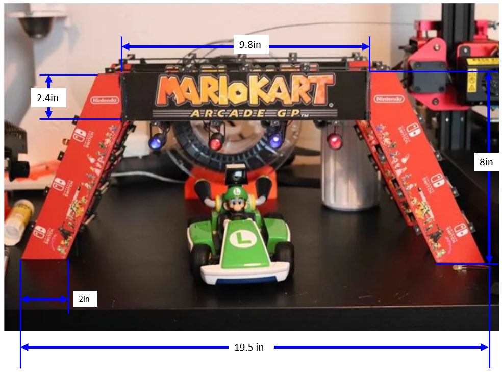
- MarioBot will have track banners with the dimensions shown in Figure 2.
- MarioBot will have a maximum playfield size of 10ft x 12ft.
- MarioBot shall have items disappear from inventory after one use.
- MarioBot shall pick up items by running over different colored cards scattered around the track.
- MarioBot shall have item boxes go on 1-minute internal cooldowns after a player travels through it.
MarioBot will communicate with other players about item boxes on cooldown.(Waived)- MarioBot shall have two different speed classes for its race. The first speed class will travel
1.7 ft/secand the second speed class will travel2 ft/sec, which was calculated in Figure 1. (Waived) - MarioBot shall have an increased speed of 4 ft/sec when the boost item is used.
- The user shall be able to change the number of laps on the ArxRobot App. MarioBot will have a customizable lap counter for each race.
- The user shall be able to select which of the two-game modes Mariobot will operate in. MarioBot shall have two game modes: Multiplayer and Time Attack.
- MarioBot will be able to interact with other karts, either physically or with the use of an item.
- MarioBot will be large enough to encompass the 3Dot Board and custom circuitry.
- Mariobot shall not drive if the specified lap count is exceeded.
- Mariobot shall have differential drive steering. This is a customer-directed requirement.
Constraints
19. All robots shall contain one or more custom-designed 3DoT shields. The 3DoT shield(s) incorporates interface electronics between the 3DoT board and sensors and/or actuators unique to the robot. Due to COVID 19 restrictions, each engineer shall submit a custom functional SMD-based PCB.
20. Due to COVID-19 restrictions, each team member will construct their own 3DoT robot. The cost of each completed robot will be defined by the team. It is recommended that the cost not exceed $250.
21. Team member robots will be completed by the date of the mission (i.e., starting the week of May 9, 2021). Project completion includes all documentation and capability to execute the mission.
22. The mass of the robot will not exceed 350 grams.
23. Power to the robots will be provided by the 3.7V Li-Ion battery included with the 3DoT board, with a capacity of 700 mAh (min) to 750 mAh (max) and a power rating of 2.59 (min) – 2.775Wh (max) (included with the 3DoT board). Use of an external battery will use a 2.0mm PH series JST connector located on the 3DoT board and covered in a separate requirement.
24. All Safety regulations as defined in Section 4.3 Hazards and Failure Analysis of this document will apply to the shipping, handling, storage, and disposal of LiPo batteries.
25. The diameter of power-carrying wires will follow the American Wire Gauge (AWG) standard.
26. Software will be written in the Arduino De facto Standard scripting language and/or using the GCC C++ programming language, which is implements the ISO C++ standard (ISO/IEC 14882:1998) published in 1998, and the 2011 and 2014 revisions.
27. The robot will use the 3DoT v9.05 or later series of boards to achieve the mission objective.
Supplemental Figures
Figure 1: Mario Kart Live Home Circuit Speed Calculations Overlay
Figure 1 is an overlay of two frames from the MarioKart Live Home Circuit youtube trailer video.
 Figure 1.1: Mario Kart Live Home Circuit Frame Side By Side
The first frame starts at 2:52 seconds into the video. The second frame is two seconds after. Overlaying the frames we can see the distance traveled by the RC car in the time of 2 seconds. The dimensions of the MarioKart RC car are also known. It has a length of 8.5 inches. Using the MarioKart RC care as a reference length, we can determine that it travels 5 car lengths in 2 seconds in the ‘50CC’ race class. In the ‘100CC’ race class, it travels 5.5 car lengths in 2 seconds. With this information, we are now able to calculate the speed at which it travels at.
Therefore, we were able to determine that MarioBot should travel at 1.7 ft/sec for 50CC race mode and 2 ft/sec for 100CC race mode.
System/Subsystem/Specifications Level 2 Requirements
- MarioBot shall be able to identify an item based on the color of the card within 166 ms seconds of being above the card. Colors include pink, green, and red. This requirement is derived from L1.9, L1.11, and L1.12.
- MarioBot will have three usable items from colored cards. These items include the green shell from the green card, the mushroom from the red card, and the pink heart from the pink card. This requirement is derived from L1.9, L1.12, L1.16, and L2.1.
- MarioBot shall stop for 2 seconds when it is hit by the green shell item. This requirement is derived from L1.16 and L2.2.
- MarioBot shall not be affected by other players when holding a pink heart item. This requirement is derived from L1.16 and L2.2.
- MarioBot shall get a speed boost when using the mushroom item. This requirement is derived from L1.12 and L2.2.
- MarioBot shall have a speed boost for 1.5 seconds. This requirement is derived from L1.12, L2.2. and L2.5.
- MarioBot shall go back to its race class speed rating after the mushroom item has been activated. This requirement is derived from L1.11, L1.12, and L2.6.
- MarioBot shall utilize items through the user’s input through ArxRobot App. This is derived from L1.14 and L1.16.
- MarioBot shall display its lap counter and items to the user through the Arxrobot App. This requirement was derived from L1.13 and L1.14.
MarioBot shall detect RFID tags in the banner within a distance of x cm. This requirement is derived from L1.4, L1.5, and L1.15.(Waived)- MarioBot shall be able to record lap times as it passes through the race banners. This requirement is derived from L1.4, L1.5, and L1.15.
- MarioBot shall be able to record how many laps it has completed and the laps still remaining. This requirement is derived from L1.13. and L1.15, L2.9, and L2.11.
- MarioBot shall have a settings option within the Arxrobot App to change between race classes, laps, and game modes. This requirement is derived from L1.12, L1.14, L1.16, and L1.8.
MarioBot shall have RFID tags’ dimensions fit within the area of the track banners. This requirement is derived from L1.6. (Waived)Mariobot shall have an RFID reader detect the RFID tag within x milliseconds. This requirement is derived from L1.5, L2.10, L2.11.(Waived)- MarioBot will have colored cards that are 50mmx50mmx.4mm in length, width, and thickness. This requirement is derived from L1.9, L2.1, L2.2.
- MarioBot will have color sensors 3 mm off the ground to ensure that it does not impede the kart and to ensure it can still read the colored card off the ground. This requirement is derived from L1.9, L2.1, L2.2.
- MarioBot shall be able to ‘throw’ the Green Shell item to vehicles at a maximum of 457.2 mm line of sight inches in front of it. This requirement is derived from L1.7, L1.17, and L2.18.
Allocated Requirements / System Resource Reports
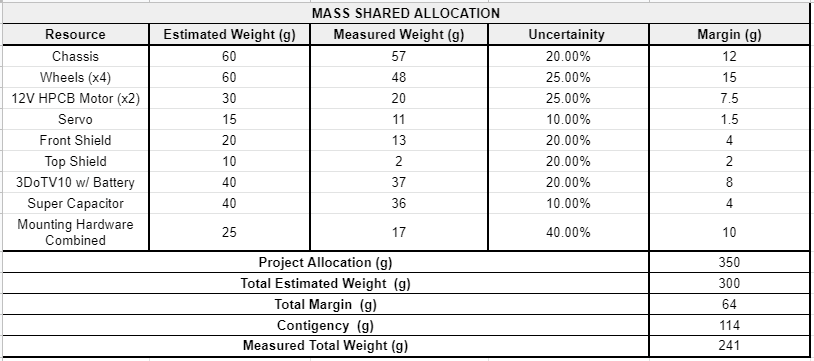
Figure 3 MarioBot Mass Allocation
Figure 3 shows MarioBot’s Mass Allocation. Each sub-component was given an estimated weight and then measured. As shown by the table, MarioBot has a total project allocation of 350g. MarioBot’s final total weight was 241g, which is in compliance with our constraints.
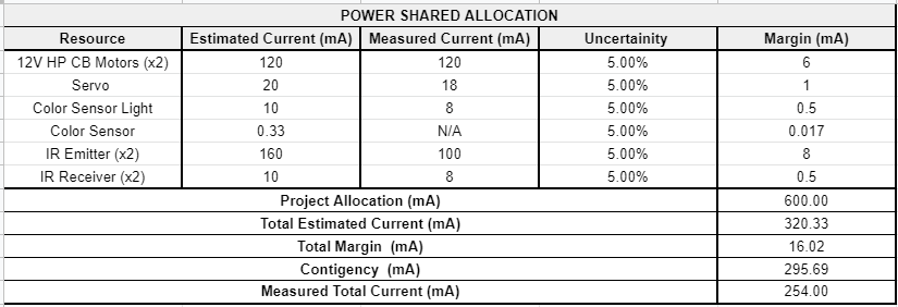
Figure 4 MarioBot Power Shared Allocation
Figure 4 shows MarioBot’s Power Allocation. Each sub-component had an estimated current draw from the datasheet. The battery on the 3DoTv10 Board has 750mA hours maximum capacity. Assuming a depth of discharge of 80%, MarioBot has a project allocation of 600mA. The estimated current draw was 320mA and the total measured current was 254mA. The total measured current was assuming no stall current on the Motors and Servo. The current on the Color Sensor was also not able to be measured.
Project Report
The following section is the Work Break Down Structure (WBS) and the Project Break Down Structure (PBS) for MarioBot.
Project WBS and PBS
Project Work Breakdown Structure (WBS) and Product Breakdown Structure (PBS)
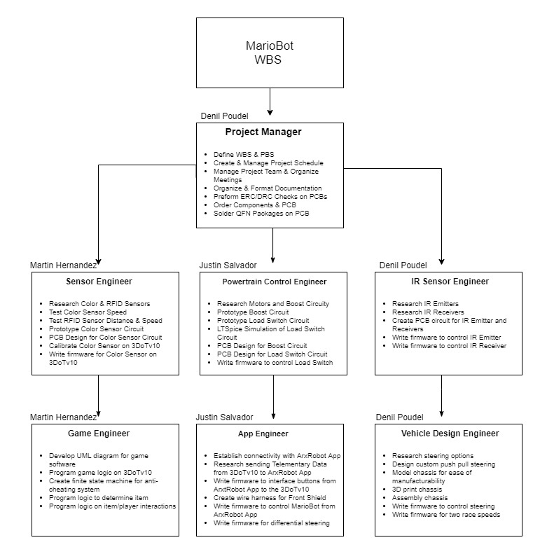 Figure 5 MarioBot Work Breakdown Structure (WBS)
Figure 5 shows MarioBot’s work breakdown structure (WBS). MarioBot was structured as a project team and only had three team members, therefore each team member had multiple roles.
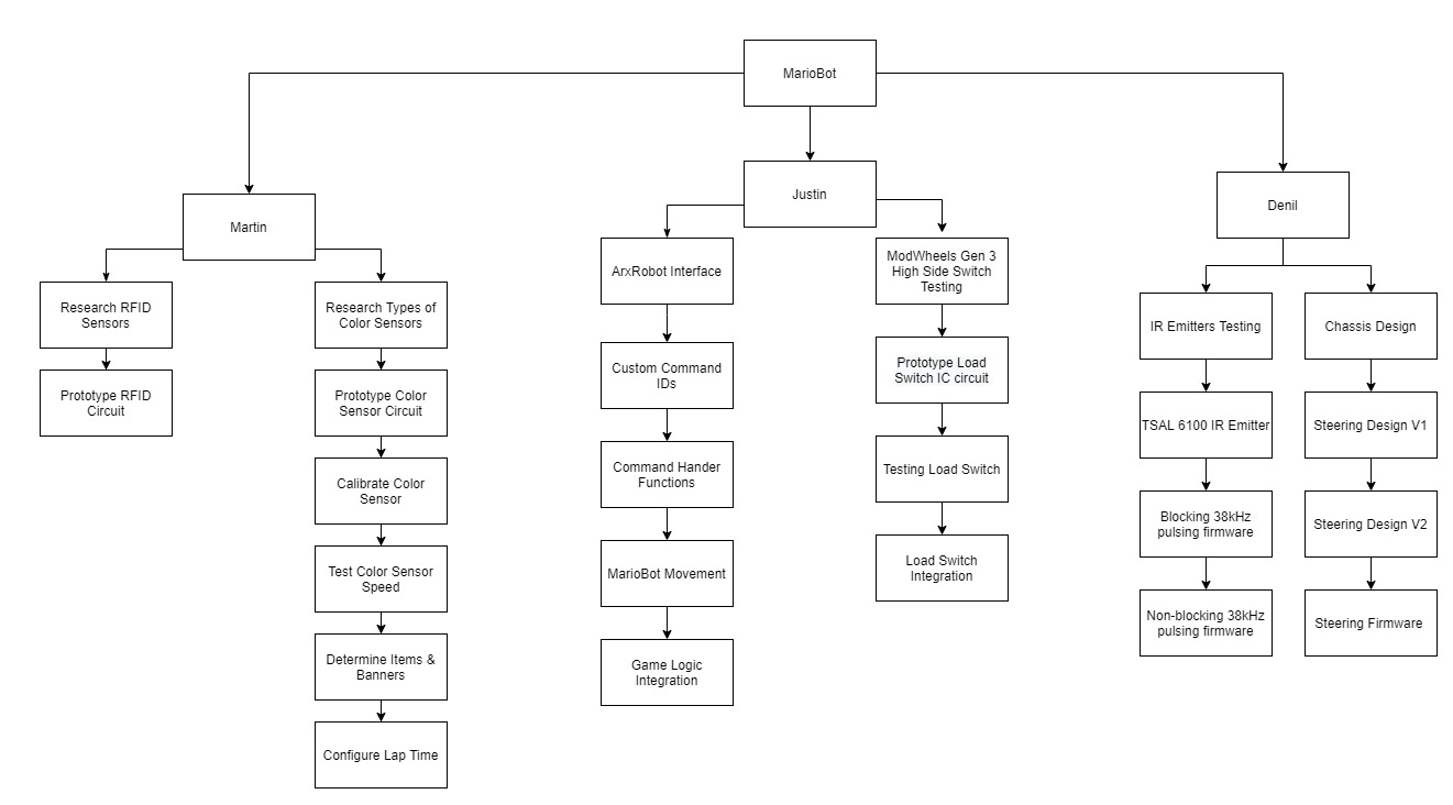 Figure 6: MarioBot Product Break Down Structure
Figure 6 shows MarioBot’s product breakdown structure (PBS). The RFID Sensor and the RF Sensor were scrapped early into the testing.
Cost
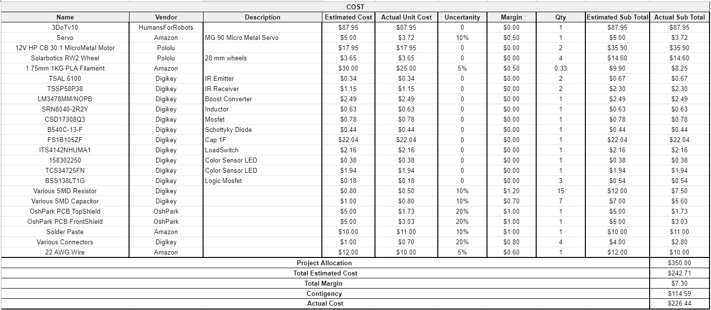 Figure 7 MarioBot Project Cost
Figure 7 shows MarioBot’s Per Vehicle Project Cost. MarioBot had a total budget of $350 per vehicle, with a contingency of about $115. MarioBot had very little uncertainty in most costs as they were listed by unit price on websites such as Digikey. Most of the uncertainty was for parts that were grouped together such as connectors, resistors, and capacitors. There was also uncertainty for the Servos from Amazon as the prices fluctuated and for PCB orders from OshPark. In the end, MarioBot finished the project with an actual cost of about $227 per vehicle.
Schedule
Concept and Preliminary Design
The following section will showcase MarioBot’s initial design decisions, adaptions, and final proposed solutions. MarioBot was inspired by ModWheels Gen 3 and added on by further incorporating some unique features as shown below.
Literature Review
Each engineer has done extensive research when it came to the MarioBot project. This includes determining the appropriate solutions for our steering mechanism, chassis design, methods of transmitting and receiving information, as well as the speed at which MarioBot will run at. Moreover, additional research was done in regards to the ArxRobot application, such that our conceptual designs could be implemented. With the extensive research resulting in many different solutions, the MarioBot team mutually decided which components would be used based on the requirements that we originally constructed. Shown below are the research each engineer has done:
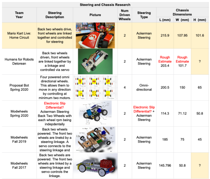 Figure 8.1 Engineer Denil’s Steering and Chassis Research
Figure 8.1 shows research on previous 4 wheeled 3DoT projects and their different types of steering.
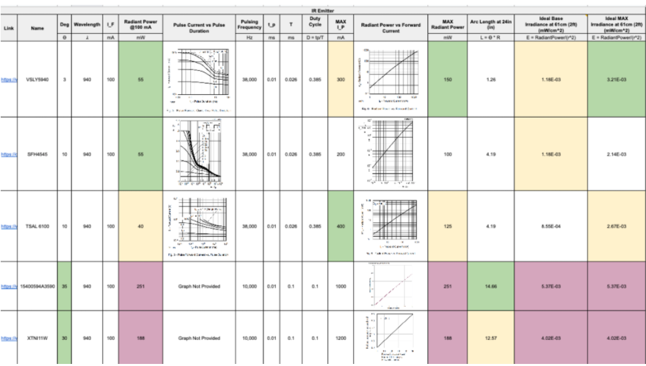 Figure 8.2 Engineer Denil’s IR Emitter Research
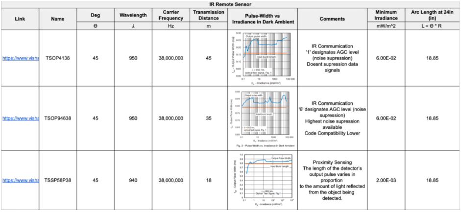
Figure 8.2 shows research on various types of IR Emitters and the pros and cons of each model of IR Emitters.
Figure 8.3 Engineer Denil’s IR Remote Receiver Research
Figure 8.3 shows research on various types of IR Remote Receivers.
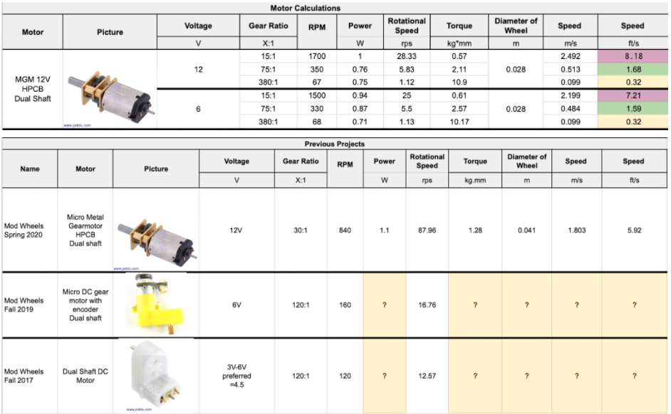 Figure 8.4 Engineer Justin’s Motor Research
Figure 8.4 shows research on various types of Motors and the speed and torque associated with each one with a specified wheel diameter.
Design Innovation
One of the projects that inspired the creation of MarioBot was the boosting mechanism that was being used in the ModWheels Generation 3 project. Their main intention was to implement a solution such that their robot would temporarily increase its normal speed in order to perform “stunts”. From this, the MarioBot team analyzed their implementation of the boost converter and its interface with the supercapacitor. Observing their interconnections between components, we noticed a transistor configuration that connects the supercapacitor to the motors. Looking further into this matter, the ModWheels team created a high side switch, where a pin from the 3DoT board will serve as the driving force to this switching configuration. Further detail is provided in an additional blog post, where it further explains the process in which this high side switch configuration that was created with discrete components was now replaced with a single integrated circuit (IC) chip that performs the same functionality. This new IC, specifically known as the ITS4142N Load Switch, underwent various testing iterations before the MarioBot team built up enough confidence to confirm that this component would be an innovative solution to improving the design of the most recent ModWheels project.
System Design / Final Design and Results
MarioBot’s final design incorporates three subsystems to satisfy all of our requirements. MarioBot originally in the Conceptual Design Review had five subsystems but the RFID Subsystem and the RF Communication Subsystem were de-scoped and waived.
The four final subsystems in MarioBot are as follows:
Color Sensor:
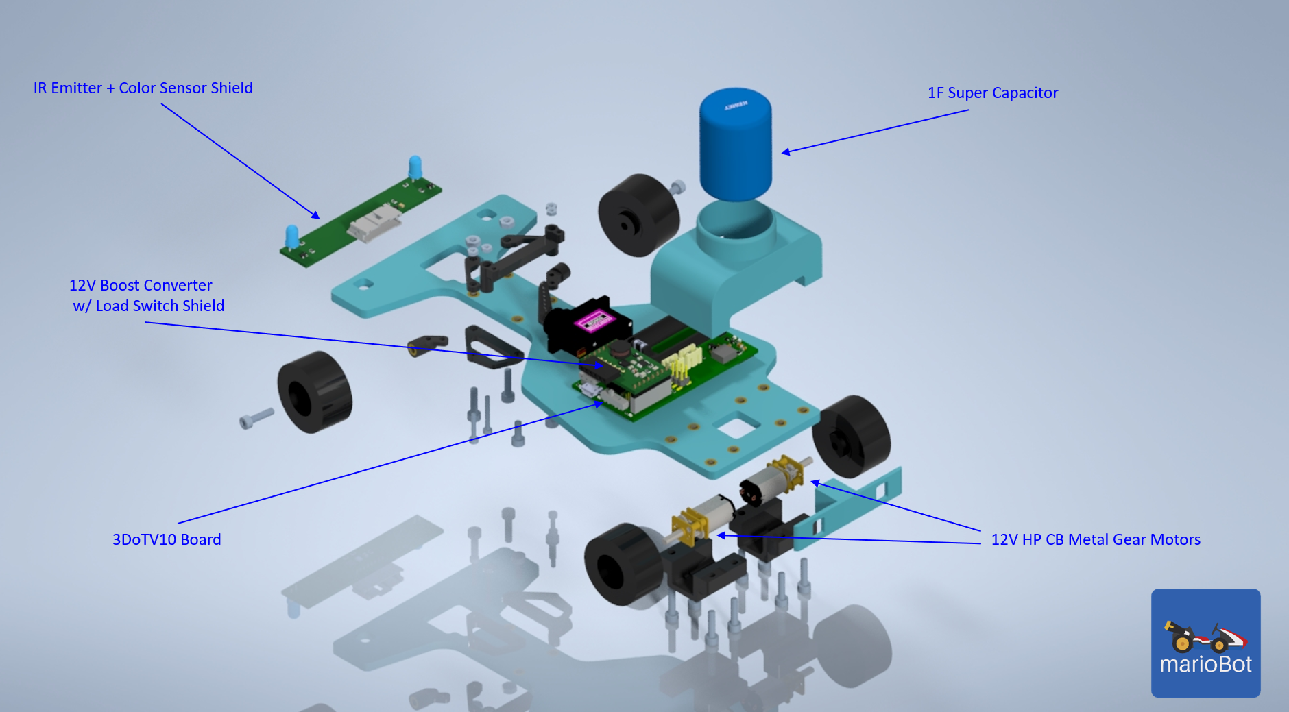
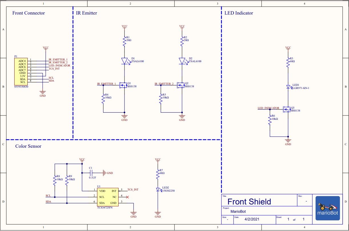
The TCS34725FN Color Sensor allows MarioBot to determine the banners on the track and the items picked up by the player. The color sensor communicates the RGB values to the 3DoTv10 board and the firmware determines the color associated with the RGB value. The color is mapped to an associated item or banner. If a player goes through the wrong banner, MarioBot determines that the player is cheating. If a player run over a colored card, MarioBot lets the player use the associated item with the card.
IR Emitter/Receiver:
The TSAL6100 IR Emitter allows MarioBot to “throw” green shells at other players. The TSAL6100 is pulsed at a carrier frequency of 38kHz with a message modulation frequency of 1kHz. Originally in our Conceptual Design Review, the TSAL6100 was controlled via 556 Timer that generated the 38kHz and 1kHz signal. This was changed to using the internal hardware timer interrupts on the 32U4 on the 3DoTv10. This allows the TSAL6100 to communicate with the TSSP58P38 IR Remote Receiver. The TSSP58P38 has a 38kHz bandpass filter built-in, which filters out any ambient IR from the environment. The TSSP58P38 will output a logic low signal when it detects any 38kHz IR signal. This signal is read by the 32U4 and triggers game logic code.
Boost w/ Load Switch:
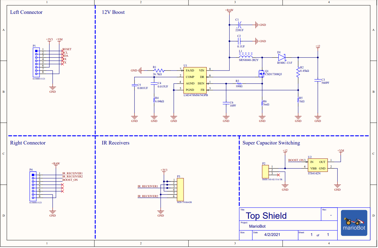
The LM3478MM Boost Converter steps up the 3.7V from the battery on the 3DoTv10 to 12V to charge the FS1B105ZF 1F Supercapacitor. If the player has the mushroom item, MarioBot can then discharge the Supercapacitor into the motors for a quick burst of speed. The switching of the capacitor is handled through an ITS4142 Load Switch. The load switch takes a logic signal from the 32U4 to connect the supercapacitor power rail to the motor power rail.
Similar to Mod Wheels Gen 3, The 5V and 5V_VM line need to have a Schottky diode placed between the solder jumpers for reverse voltage protection. This lets MarioBot use the 5V normally for motor usage and then switch over via Load Switch to the 12V from supercapacitor.
System Block Diagram
Detailed System Block Diagram(s) of the design. This is an updated and more detailed version of the block diagram presented as part of the conceptual design. Identify connectors, numbers of wires in a bus, and when practical, the names of the wires and buses. As part of your write-up, walk the reader through each subsystem/component block and how they are interconnected (i.e., subsystem and interface descriptions).
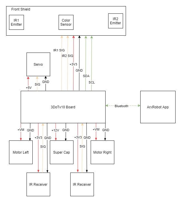
Figure 9: MarioBot System Block Diagram
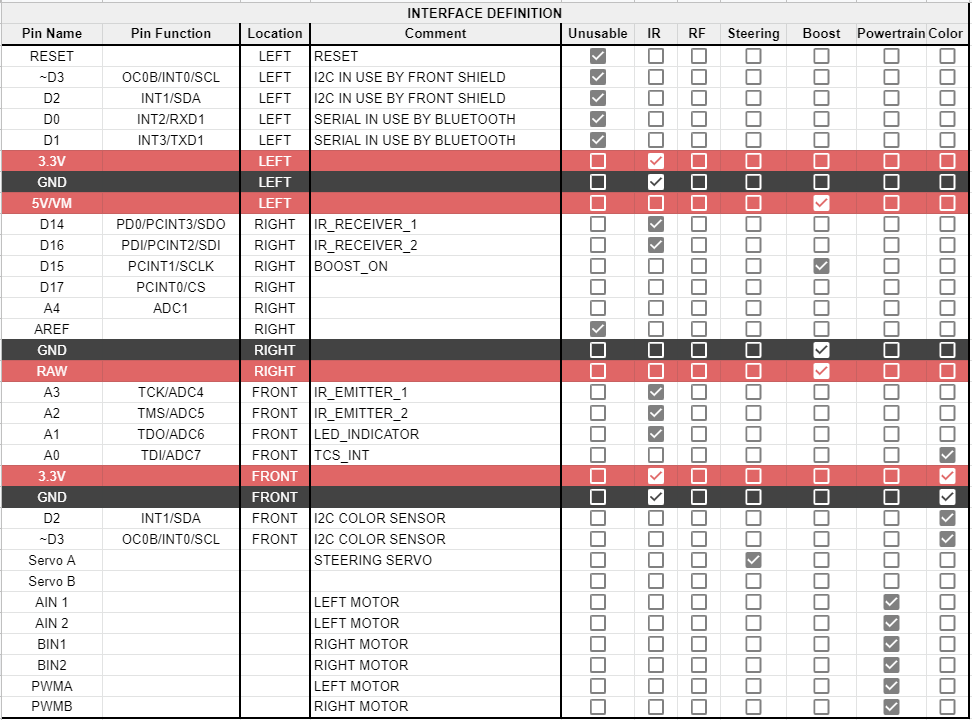
Figure 9 shows MarioBot’s system Block Diagram. At the heart of it is the 32U4 on the 3DoTv10 Board. The high-level connections are shown in the system block diagram above. The specific pins are shown in the interface matrix in the next section.
The ArxRobot App interfaces with the 3DoTv10 using Bluetooth. This allows the player to control the servo, motors, and IR emitters throughout the race.
MarioBot utilizes 4 different power rails. The first power rail is the +3v3V rail that supplies the Front Shield and IR Receivers. Depending on the load switch the +VM rail can be tied to +12V from the supercapacitor or +5V from the 3DoTv10 board. The Servos are wired on a different 5V rail from VM.
The motors are controlled via PWM to have different RPM as selected by the player on the ArxRobot app. Depending on the player’s selection the Motors can be configured in the “50cc” race class or “100cc” race class.
The supercapacitor is charged via the +12V line from the custom Top Shield boost converter on the 3DoTv10 board. Once triggered by the player, the load switch connects the +12V line from the supercapacitor to the +VM line of the motors to boost the speed.
The IR receivers send a low signal once they detect a 38kHz IR pulse from another MarioBot. This is read by the 32U4 and triggers an interrupt service routine.
The IR emitters are located on the front shield and are controlled by bit-banging the IR1 and IR2 signal lines. The IR1 and IR2 signal lines control a MOSFET that toggles the IR led at 38kHz.
Also located on the front shield is the color sensor. The color sensor communicates to the 32U4 on the 3DoTv10 board using the I2C protocol. It continuously reads the ground in front of MarioBot for different colors. It sends the color data to the 32U4 as R, G, &B values. The 32U4 associates the R, G,&B according to predefined ranges and associates them with banners or items.
Interface Definition
Modeling/Experimental Results
The various modeling and experiments that the MarioBot team has done throughout the semester were covered in separate blog posts, where each engineer will describe their research and design in further detail. These include components such as IR and RFID sensors, an IC chip that replaces discrete circuit models, as well as the telecommunication between the 3DoT board and the ArxRobot mobile application.
In reference to the blog post, “High Side Switch – Research and Innovation”, the engineer responsible discusses the process that was used to simplify the ModWheels Generation 3 boost mechanism. Moreover, the engineer walks through the testing process to validate the similarities between the original design and the new conceptual design.
Boost Circuity w/ Load Switch:
As shown in the blog post ” IR Sensor Communication Research” Denil discusses the pros and cons of each type of IR sensor and showcases experimental tests as to why MarioBot went with the TSAL6100 and the TSSP58P38.
IR Sensor Communication:
As explained in the RFID Blog Post, we would have to scrap the RFID because it would not have been able to complete our set objectives. This was experimentally proven with multiple trials to show that the detection time would not have been fast enough.
Mission Command and Control
Electronic Design
MarioBot utilizes a unique variety of sensor suites. The front shield of MarioBot encompasses the TSAL6100 IR Emitter and TCS34725FN Color Sensor. The top shield encompasses the LM3478 Boost Converter and the ITS4142 Load Switch. The top shield also has connectors for the TSSP58P38 Digital Remove IR Receiver and the FS1B105ZF 1F Capacitor. MarioBot expanded on ModWheel’s Gen 3 design with the addition of the Load Switch to the Boost Circuit.
PCB Design
IR Emitters
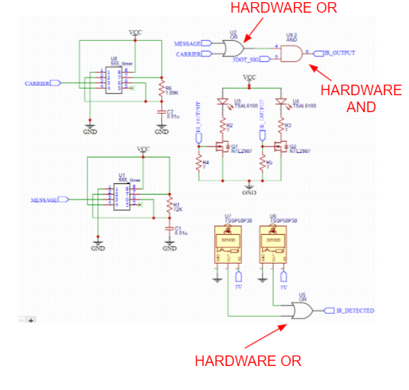 Figure 12: MarioBot IR Conceptual Design Review Schematic
Figure 12 shows MarioBot’s original conceptual design review schematic for the IR Receiver and Emitter. Originally the IR Emitters were controlled via two 555 timers (or one 556 timer) that created the 38kHz carrier signal and the 1kHz message signal and hardware OR’ and AND’d them together with a signal from the 34U2. After our conceptual design review, we moved to software interrupt timers from the 32U4 and removed all the extra circuitry.
Color Sensor
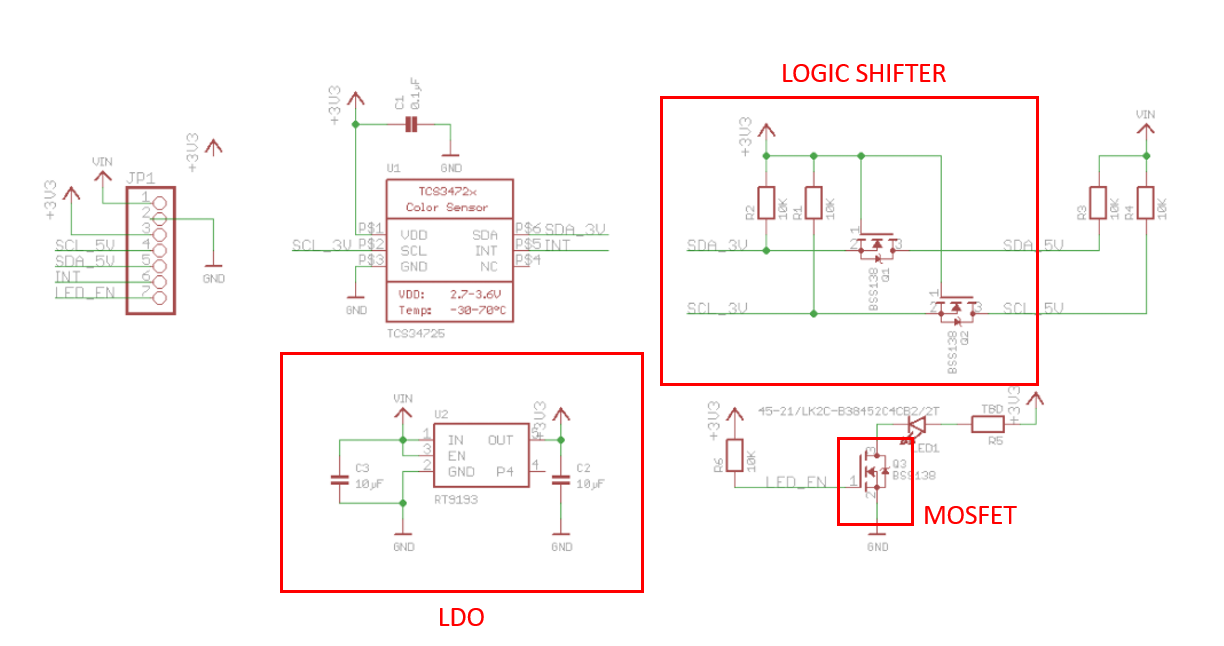 Figure 13: MarioBot Color Sensor Conceptual Design Review Schematic
Figure 13 shows MarioBot’s original conceptual design review schematic for the Color Sensor. This schematic is provided as an open-source by Adafruit. After our conceptual design review, we modified the schematic to remove the LDO, MOSFET, and Logic Shifter circuitry as we did not need them.
Front Shield Schematic
Figure 14: MarioBot Front Shield Schematic
Figure 14 shows MarioBot’s Final Front Shield Schematic. It encompasses the TSAL6100 IR Emitter and the TCS34725FN Color Sensor with out an of the extraneous circuitry from the conceptual design review.
Figure 15: MarioBot Front Shield PCB
Figure 15 shows MarioBot’s Front Shield PCB Design. The PCB design was created in Altium and was manufactured by OshPark.
 Figure 16: MarioBot Front Shield Physical PCB
Figure 16 shows MarioBot’s Front Shield PCB with all the components soldered onto it.
Boost and Load Switch:
MarioBot did not have a Boost and Load Switch schematic for the Conceptual Design Review. MarioBot used the WEBENCH Power Design tool by Texas Instruments to design the 3.7V to 12V Boost Converter schematic. Then we choose a load switch that is rated for 1.4A at 12+V to switch the power rails.
Figure 17 MarioBot Top Shield Schematic
Figure 17 shows MarioBot’s top shield schematic. The top shield encompasses the boost converter circuitry, the supercapacitor load switch, and the ir receiver connections.
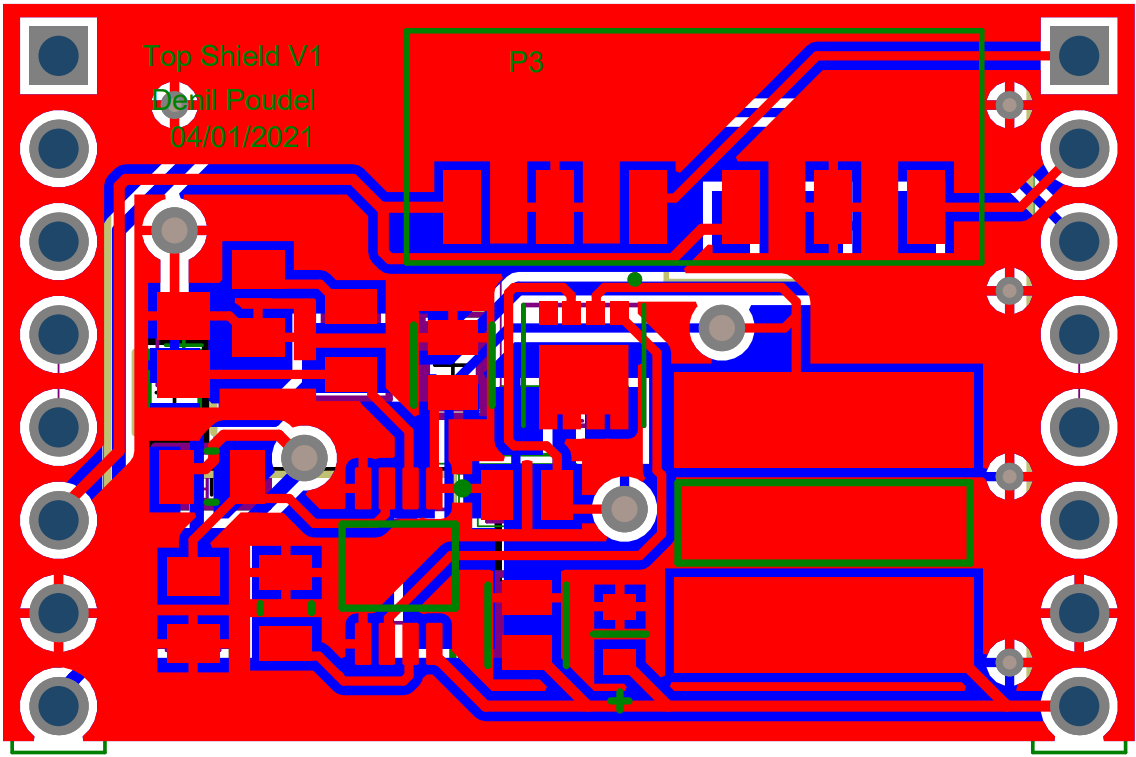 Figure 18 MarioBot Top ShieldPCB Design
Figure 18 shows MarioBot’s Top Shield PCB Design. The PCB design was created in Altium and was manufactured by OshPark.
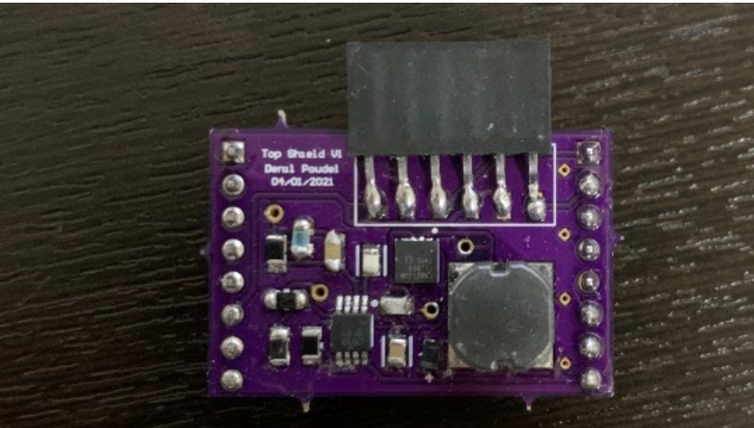
Figure 19: MarioBot Top Shield Physical PCB
Figure 19 shows MarioBot’s Top Shield PCB with all the components soldered onto it.
Firmware
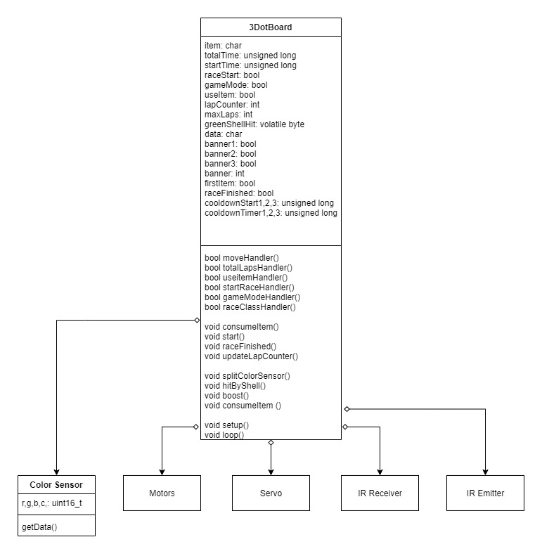
Shown below is the code that was used to interface between the ArxRobot mobile application and the 3DoT board itself. This relies heavily on the custom command IDs and the command handler functions that correspond to them. The main component of this block of code would be the MOVE command, which will drive MarioBot forward, as well as implementing our steering mechanism. Various additional features of our game logic are included as well. This is also important as it ties all the functional and game code together.
ArxRobot App + Driving + SteeringArxRobot ArxRobot; // instantiated as ArxRobot at end of class header Servo servoA; Motor motorA; // motorA object Motor motorB; // motorB object Neotimer myTimer = Neotimer(2000); // delay for testing Neotimer hitTimer = Neotimer(2000); // delay for when hit with green shell Neotimer boostTimer = Neotimer(1500); // delay for boost turn on #define loadSwitch 15 #define MOVE 0x01 #define setTotalLaps 0x44 // command IDs #define useItem 0x45 // 0x00 --> 0x3F are used for built-in commands #define startRace 0x46 // custom commands can use 0x40 --> 0x5F #define gameMode 0x47 #define raceClass 0x48 #define updateMushroom 0x49 #define updateHeart 0x50 #define updateGreenShell 0x51 #define updateLapsRemaining 0x52 #define updateLapsCompleted 0x53 int lapCounter; int lapTotal; int maxLapCount = 2; unsigned long startTime; unsigned long totalTime; const uint8_t CMD_LIST_SIZE = 11; // total number of commands //angles have been experimentally adjusted based on servo orientation // param array includes 4 indexes // param[0] = motorA direction ; //0x01 = FORWARD , 0x02 = BACKWARD , 0x04 = Slider Released // param[1] = motorA speed // param[2] = motorB direction // param[3] = motorB speed // COMMAND HANDLERS bool moveHandler (uint8_t cmd, uint8_t param[], uint8_t n) { int pwm; if( raceSpeedFast == TRUE){ pwm = 255; }else{ pwm = 100; } // // Serial.print(param[0]); // Serial.print(" , "); // Serial.print(param[1]); // Serial.print(" , "); // Serial.print(param[2]); // Serial.print(" , "); // Serial.println(param[3]); if (param[0] == 0x02 && param[2]==0x01 && moveEnabled == TRUE){ //turns servo left //servoA.write(120); servoA.write(120); // denil's servo motorA.go(1,pwm); motorB.go(1,255); // when we have chassis, include differential steering return false; } if (param[0] == 0x01 && param[2]==0x02 && moveEnabled == TRUE){ //turns servo right servoA.write(60); //servoA.write(0); denils servo motorA.go(1,255); motorB.go(1,pwm); // when we have chassis, include differential steering return false; } if (param[0]==0x04 && param[2]==0x04 && moveEnabled == TRUE){ // nothing "stall" servoA.write(90); //servoA.write(60); / denil's servo } if (param[0] == 1 && param[2] == 1 && moveEnabled == TRUE) { //go straight motorA.go(1, 255); motorB.go(1, 255); } } // moveHandler bool setTotalLapsHandler(uint8_t cmd, uint8_t param[], uint8_t n){ Serial.print("Lap Count: "); Serial.println(param[0]); maxLaps = param[0]; return false; }//setTotalLapsHandler bool useItemHandler(uint8_t cmd, uint8_t param[], uint8_t n){ if(param[0] == TRUE){ Serial.println("Item Stored"); } if(param[0] == FALSE){ Serial.println("Item used"); myTimer.start(); } return false; } // use item bool startRaceHandler(uint8_t cmd, uint8_t param[], uint8_t n){ if(param[0] == TRUE){ Serial.println("Race Started"); moveEnabled = TRUE; } if(param[0] == FALSE){ Serial.println("Race NOT Started"); moveEnabled = FALSE; } return false; } // begin race bool gameModeHandler(uint8_t cmd, uint8_t param[], uint8_t n){ if(param[0] == TRUE){ Serial.println("Multiplayer"); } if(param[0] == FALSE){ Serial.println("Time Attack"); } return false; } // change game mode bool updateLapsCompletedHandler(uint8_t cmd, uint8_t param[], uint8_t n){ //param[0] = lapCounter; param[0] = maxLapCount; return false; } // update lap count // //bool updateMushroomHandler(uint8_t cmd, uint8_t param[], uint8_t n){ // if(item == "m"){ // param[0] = TRUE; // } // else{ // param[0] = FALSE; // } // return false; //} // display mushroom // //bool updateHeartHandler(uint8_t cmd, uint8_t param[], uint8_t n){ // if(item == "h"){ // param[0] = TRUE; // } // else{ // param[0] = FALSE; // } // return false; //} // display hearts // //bool updateGreenShellHandler(uint8_t cmd, uint8_t param[], uint8_t n){ // if(item == 's'){ // param[0] = TRUE; // } // else{ // param[0] = FALSE; // } // return false; //} // display shell bool updateLapsRemainingHandler(uint8_t cmd, uint8_t param[], uint8_t n){ param[0] = setTotalLaps - lapCounter; Serial.println(param[0]); return false; } // display laps bool raceClassHandler(uint8_t cmd, uint8_t param[], uint8_t n){ if(param[0] == TRUE){ Serial.println("100CC Race Class Set!"); } if(param[0] == FALSE){ Serial.println("50CC Race Class Set!"); } return false; } // race class // END OF COMMAND HANDLERS void hitByShell(){ moveEnabled = FALSE; hitTimer.start(); } void boost(){ digitalWrite(loadSwitch, HIGH); boostTimer.start(); } ArxRobot::cmdFunc_t onCommand[CMD_LIST_SIZE] = {{MOVE,moveHandler},{setTotalLaps, setTotalLapsHandler},{useItem,useItemHandler},{startRace, startRaceHandler},{gameMode,gameModeHandler},{updateLapsCompleted, updateLapsCompletedHandler},{updateLapsRemaining,updateLapsRemainingHandler},{raceClass,raceClassHandler}}; //{updateMushroom, updateMushroomHandler},{updateHeart,updateHeartHandler},{updateGreenShell,updateGreenShellHandler}, // additional handlers for testing Packet motorPWM(MOTOR2_CURRENT_ID); // initialize the packet properties to default values void setup() { Serial.begin(9600); // default = 115200 ArxRobot.begin(); ArxRobot.setOnCommand(onCommand, CMD_LIST_SIZE); motorPWM.setAccuracy(1); // change sensor accuracy from +/-2 DN to +/-1 DN (-- this line is optional --) motorPWM.setSamplePeriod(500); // change sample period from 1 second to 0.5 seconds (-- this line is optional --) servoA.attach(4); motorA.begin(AIN1,AIN2); // pinouts of motor A motorB.begin(BIN1,BIN2); // pinouts of motor B } void loop(){ ArxRobot.loop(); if(hitTimer.done()){ Serial.println("Finished my hit timer"); moveEnabled = TRUE; hitTimer.reset(); } if(boostTimer.done()){ Serial.println("Finished my boost"); digitalWrite(loadSwitch,LOW); } #if defined(__AVR_ATmega32U4__) || defined(__AVR_ATmega16U4__) uint16_t pwm_reading = (uint16_t) OCR4D; // read 8-bit Output Compare Register Timer 4D and cast to 16-bit signed word motorPWM.sendSensor(pwm_reading); #else // Timer/Counter 0 registers set by UNO Bootloader (freq. = 1 Khz) // Timer/Counter Control Registers TCCR0B = 0x03 (Prescaler of 64) and TCCR0A (Fast PWM, TOP = 0xFF) = 0x03 uint16_t pwm_reading = (uint16_t) OCR0B; motorPWM.sendSensor(pwm_reading); #endif }
Shown below is a simple sketch that will utilize a pin from the 3DoT board in order to test the new load switch that is being implemented in our design. Toggling between the HIGH and LOW states verifies the functionality of the load switch.
Load Switch Code
// test the load switch
#define loadSwitch 12
void setup() {
// put your setup code here, to run once:
pinMode(loadSwitch,OUTPUT);
}

void loop() {
// put your main code here, to run repeatedly:
digitalWrite(loadSwitch, LOW);
delay(5000);
digitalWrite(loadSwitch, HIGH);
delay(5000);
}
Shown below is the code that was created for our color sensor that will detect the various colored cards that will be used in our design. Based on each value of Red, Green, and Blue, this code will determine which color it is reading
Color Sensor Code
class ColorSensor{
uint16_t r, g, b,c;
Adafruit_TCS34725 tcs;
public:
ColorSensor(){
tcs = Adafruit_TCS34725(TCS34725_INTEGRATIONTIME_50MS, TCS34725_GAIN_1X);
}

char getData() {
char color;
tcs.getRawData(&r,&g,&b,&c);
//Serial.print("R: "); Serial.print(r, DEC); Serial.print(" "); //Red Value
//Serial.print("G: "); Serial.print(g, DEC); Serial.print(" "); //Green Value
//Serial.print("B: "); Serial.print(b, DEC); Serial.print(" "); //Blue Value
//Serial.println(" ");

if (r > 100 && r<300 && g > 100  && g < 300 && b > 100 && b< 300) { color = 'b'; //black } else { if (r > 900 && r < 1500 && g > 100 && g < 700 && b > 100 && b < 800) { color = 'r'; //red } else if (r > 1600 && r < 2000 && g > 800 && g < 1400 && b > 1000 && b < 1600) { color = 'k'; // pink } else if (r > 1000 && r < 1600 &&  g > 900 && g <  1400 && b > 200 && b < 800) { color = 'y'; //yellow } else if (r > 500 && r < 1500 && g > 100 && g < 600 && b > 100 && b < 800) { color = 'o'; //orange } else if (r > 300 && r < 600 && g > 400 && g < 600 && b > 500 && b < 800) { color = 'p'; //purple } else if (r > 100 && r < 900 && g > 500 && g < 1500 && b > 100 && b < 1100) {

color = 'g'; //green
}

else {
color = 'u'; // no specific color.
}e

}

return color;
}

};
Shown below is the code that will keep track of the laps that have been completed. The code was created such that the order in which our banners are completed matters. Not completing the banners in the correct order will print an error to the serial monitor.
updatingLapCounter
void updateLapCounter() {
bool raceFinished;
cheated= false;
switch (banner) {
case 0:
Serial.println("Just driving");
break;
case 1:
Serial.println("in case 1");
if (banner1 ==false) {
banner1 = true;
}
else {
Serial.println("just driving");
}
break;
case 2:
Serial.println("in case 2");
if (banner1 == true){
banner2 = true;
}
else {
Serial.println("You cheated");
}

Serial.println(banner1);Serial.println(banner2); Serial.println(banner3);
break;
case 3:
Serial.println("in case 3");
if (banner2 == true) {
banner3 = true;
}
else {
Serial.println("You cheated");
}

Serial.println(banner1);Serial.println(banner2); Serial.println(banner3);
break;

case 4:
static unsigned long safetyStartTime = millis();
Serial.println("in case 4");
if (banner3 == true) {
if (data != 'b'){
lapCounter++;
Serial.println(lapCounter,DEC); /* this is where the lap counter portion of Arxrobot would be*/
banner1 = false;
banner2 = false;
banner3 = false;
banner = 0;
}
else {
if (firstLap == true) {
if (data != 'b'){
banner = 0;
firstLap = false;
}
}

else {
Serial.println("Waiting to cross");
}
}
}

else {
Serial.println("You cheated");
}

Serial.println(banner1);Serial.println(banner2); Serial.println(banner3);
break;
}
}
Shown below is the code that was created such that each color that is being used in our design is assigned a specific item or banner for our race. In addition, it includes some of the game logic that fulfills some of our level requirements.
Determining items or banner
void splitColorSensor(){
switch(data) {
case 'b':
banner = 4;  //banner 4
break;
case 'p':
banner = 1; //banner 1
break;
case 'y':
banner = 2; //banner 2
break;
case 'o':
banner = 3; //banner 3
break;
case 'r':
unsigned long cooldownStart1;
if (firstItem == true) {
item = 'm';
firstItem = false;
cooldownStart1 = millis();
Serial.print(cooldownStart1);
}
else{
if (item == 'n') {
unsigned long cooldownTimer1 = millis()-cooldownStart1;
if (cooldownTimer1> 60000) {
cooldownStart1 = cooldownTimer1+cooldownStart1;
item = 'm';
Serial.print("item = ");Serial.print(item);
Serial.println(" ");
}
else {
Serial.print("item = ");Serial.print(item);
Serial.println(" ");
Serial.print("cool down time = ");Serial.print(cooldownTimer1);
}
}
else
{
Serial.println(" ");
Serial.print("Already holding item = ");
Serial.print(item);
}
}
break;
case 'k':
unsigned long cooldownStart2;
if (firstItem == true) {
item = 'h';
firstItem = false;
cooldownStart2 = millis();
Serial.print(cooldownStart2);
}
else{
if (item == 'n') {
unsigned long cooldownTimer2 = millis()-cooldownStart2;
if (cooldownTimer2> 60000) {
cooldownStart2 = cooldownTimer2+cooldownStart2;
item = 'h';
Serial.print("item = ");Serial.print(item);
Serial.println(" ");
}
else {
Serial.print("item = ");Serial.print(item);
Serial.println(" ");
Serial.print("cool down time = ");Serial.print(cooldownTimer2);
}
}
else
{
Serial.println(" ");
Serial.print("Already holding item = ");
Serial.print(item);
}
}
break;
case 'g':
unsigned long cooldownStart3;
if (firstItem == true) {
item = 's';
firstItem = false;
cooldownStart3 = millis();
Serial.print(cooldownStart3);
}
else{
if (item == 'n') {
unsigned long cooldownTimer3 = millis()-cooldownStart3;
if (cooldownTimer3> 60000) {
cooldownStart3 = cooldownTimer3+cooldownStart3;
item = 's';
Serial.print("item = ");Serial.print(item);
Serial.println(" ");
}
else {
Serial.print("cool down time = ");Serial.print(cooldownTimer3);
Serial.print("item = ");Serial.print(item);
Serial.println(" ");
}
}
else
{
Serial.println(" ");
Serial.print("Already holding item = ");
Serial.print(item);
}
}
break;
case 'u':
banner = 0;
break;
}
}
Mechanical/Hardware Design
Version 1:
Figure 20: MarioBot Chassis Version 1
Figure 20 show MarioBot’s Version 1 Chassis Design. This design has the back wheels mounted on top of the base chassis and the supercapacitor laying on its side next to the 3DoTv10 board. We found this design not to be ideal as the front wheels and back wheels’ center points were not aligned. There the front of the chassis would lift up compared to the back of the chassis giving MarioBot a weird stance.
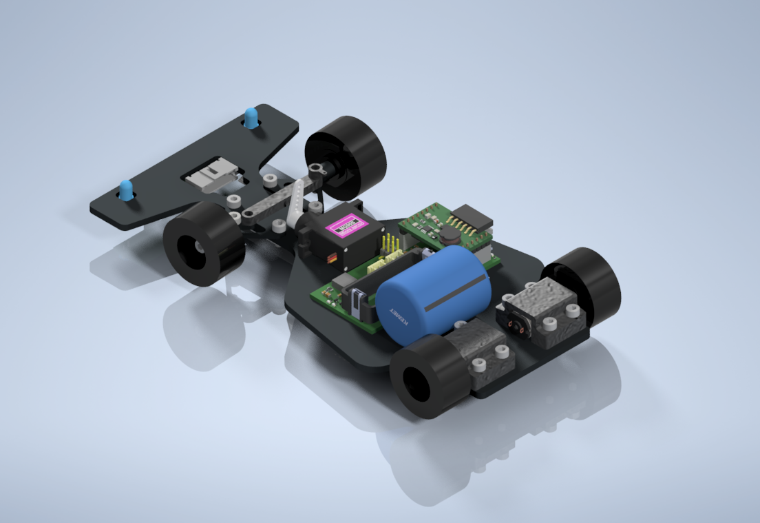
Version 2:
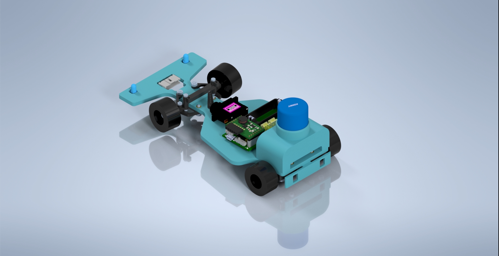 Figure 21: MarioBot Chassis Version 2
Figure 21 show MarioBot’s Version 2 Chassis Design. On the second iteration of the chassis, the back wheel mounts were moved underneath the base chassis. The supercapacitor was mounted into a slot on top of the motors. We found that shifting the extra weight of the supercapacitor on top of the motors helped the back wheels grip the road surface better and prevented the supercapacitor from rolling around.
Verification & Validation Test Plan
During the validation and verification phase of our project, we were unable to completely integrate each engineer’s responsibility into the final product, which ultimately resulted in a Fail status for some of our requirements. Based on the time constraints, however, the MarioBot team was able to complete a substantial amount of work in our efforts to create a fully functional MarioBot. Each engineer was able to individually demonstrate most of their respective responsibilities, which did validate that each of our programs is functional. In the end, the final mission was to provide MarioBots that were fully integrated, and we did not complete it in time.
The requirements and verification can be found here.
Concluding Thoughts and Future Work
We encountered many problems and mistakes throughout our project. For one, we were not prepared with our perceived lack of timers. Our IR and servo had conflicting timers which were not able to solve to showcase steering and using the shell item at the same time. In addition, there is an issue with our top shield that created a short and caused a wire to start smoking. Therefore we couldn’t show off the mushroom boost in action. Finally, the color sensor in theory would work every time; however, its RGB values would constantly fluctuate, which could be caused due to a slight change in height, minuscule coloration change in the colored cards, and rapid changes of speed.
In addition we also had to remove the RFID and RF transceiver components of the projects. These would have completed Project Requirements L1.10, L2.10, L2.14, L2.15, but they had to be waived off completely or altered to complete the main goal of the MarioBot.
References/Resources
All of MarioBot’s resources can be found here.

