Spring 2016 Pathfinder: PCB System Schematic
By:
Juan Acosta (Electronics & Control – MCU Subsystem and Firmware)
Tuong Vu (Electronics & Control – Sensors, Actuators, and Power)
Table of Contents
Introduction:
Project Pathfinder required the use of an Arduino Mega, VNH5019 motor shield, PCA9685 Servo PWM Controller, two HC-SR04 ultrasonic sensors, two servos, six DC motors, HC-06 Bluetooth Module, LED Headlights, and Buck regulator. Each device we chose to use will help us accomplish our mission by meeting set level 1 and 2 requirements. For more information on testing and implementation of these devices, visit the previous blog post Spring 2016 Pathfinder: Subsystem Design
Custom PCB Schematic:

As discussed in our Subsystem Design, we decided that it would be best if we created a custom PCB that would allow us to take advantage of the leftover pins of the Arduino Mega. So in our custom PCB design, we aimed for a PCB that would interface with the Arduino Mega as a shield. In our PCB schematic we have allotted different headers for the two ultrasonic sensors needed for obstacle collision prevention, headers for the PCA9685 Servo Controller that we chose to safely power and drive our pan and tilt servos, headers for the HC-06 Bluetooth module needed for wireless communication, headers for the L.E.D. headlights needed for lighting, and TPS56428 buck regulator needed to step down voltage to 6 volts to protect the servo driver from 7.4V.
Buck Regulator:
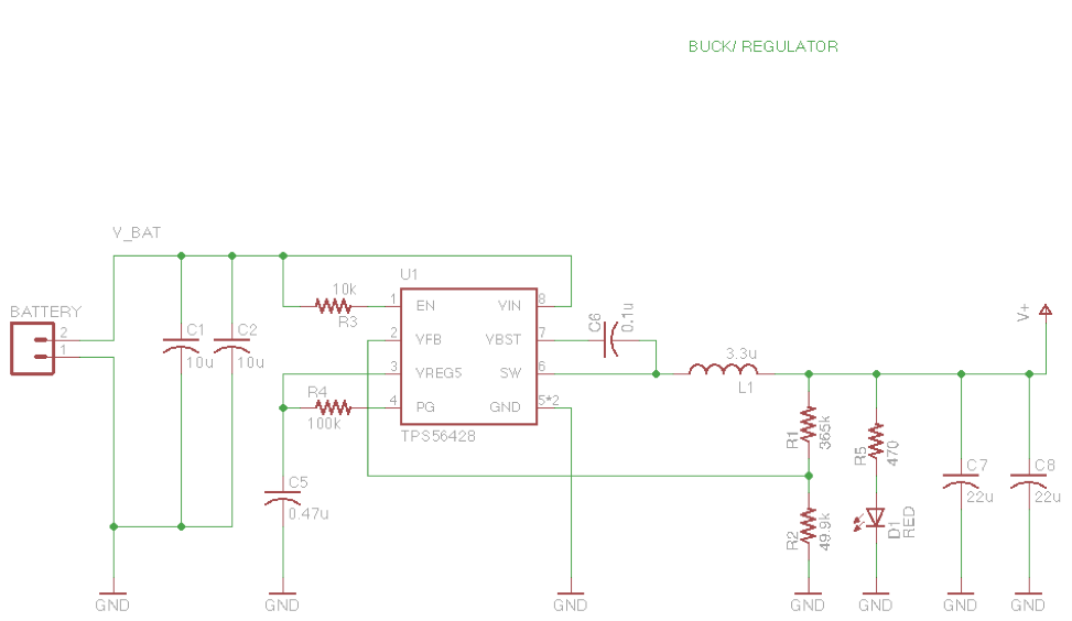
The figure above focuses on the buck regulator. We chose this buck regulator because it was found most efficient during testing. We used the data sheet provided by Texas Instruments in order to find the necessary resistance values for Resistors R1 and R2 which control the duty cycle needed for an output of 6 volts. For resistor R1 we got 355 K and 49.9 Kfor resistor R2. Aside from the necessary resistors and capacitors outlined in the guide sheet for the TPS56428, we also added capacitors C1 and C2 for noise cancellation and a red L.E.D. in series with resistor R5 in order to show when the circuit is on.
Headers:
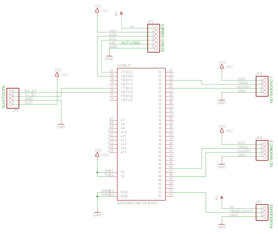
The figure above focuses on the through hole headers we will be using to directly plug in our two ultrasonic sensors, headlight L.E.D.s, Bluetooth module, and servo driver.
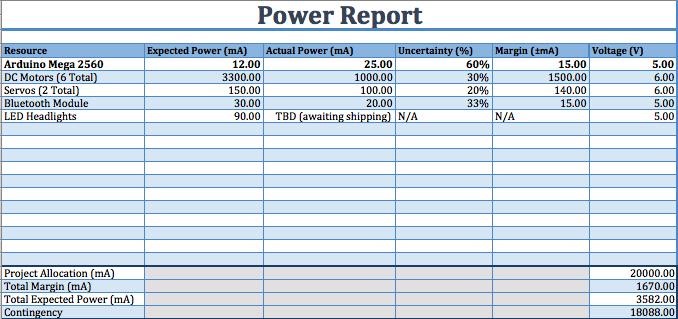
Power test
During testing it was found that the max current draw for the PCA9685 servo driver was about 140 mA. The max current draw for the HC-06 bluetooth module was 25 mA. The max current draw for the L.E.D. headlights was 90 mA. The max current draw for the motors was 1 A. Lastly, the max current draw from the HC- SR04 ultrasonic sensors was 20 mA. For more info reference the Power Report below.
Keeping all of the voltage and current ratings of each device in mind will help during the routing of the custom PCB. Because different components need different current ratings to operate normally, the size of the traces in our PCB should reflect the amount of current that will go through these traces.
Source Materials:
– EagleCAD download:
http://www.cadsoftusa.com/download-eagle/
– TPS56428 buck regulator:
http://www.ti.com/product/TPS56428
– Spring 2016 Pathfinder: Subsystem Design
http://arxterra.com/spring-2016-pathfinder-subsystem-design/