Spring 2016: 3DoT David Design Evolution
Introduction
The design has changed for the last couple weeks. By assembling the 3Dot David, problems and issues occurred, and had to be adjusted, especially for the bottom plate, legs, and top plate.
Related requirement:
As part of the level 2 system requirement follows:
The 3DoT David shall use a 3D printed chassis and legs. This follows from the project level requirement about using 3D printed parts.
Table of Contents
3DoT David plates design evolution
Bottom plate design evolution
Bottom Plate 1
The bottom plate below had some problems because the extrusion cuts made on those 10 holes. Placing the connection for the gears on those holes with the screw made the gears unstable and loose. In addition, the plank below on the right had to be super glued to the bottom of the bottom plate for 24 hours to cure. Some of the planks were easily broken off by drilling a hole on the bottom plate with the plank attached it. In the gear instability blog post on testing #1, this proves that the screws on those gears were interfering with the movements of the gears.


Bottom Plate 2
In solving the problems occurring in the 1st bottom plate, planks were then attached to the bottom plate. Gear instability was an issue. So making extrusions on the bottom plate, instead of extrusion cuts solved the issue of gear instability and movement of the gears. The holes on the bottom plate were made because the printing time exceeded 2 hours. With these holes, the printing time was exactly 2 hours.

Bottom Plate 3
The holes made on the bottom plate was not quite nice. So, “V” shaped extrusion cuts are made because they reduced less printing time, makes the design look nice. The two extrusion cuts are made for the new gearbox motors to be placed right at the bottom of it.

Bottom Plate 4
This is final design of the bottom plate. This is tested and assembled by the team. The changes made here are the 10 extrusions, where the gears are to be placed, to be 1 centimeters. The reason is the washer will be placed first, and then the gear will be placed second for it to freely rotate. In addition, securing the gears in place was an issue. To solve the issue, the use of the soldering iron will burn the 6 extrusions, where the large gears are placed, as it will form a surface that will secure it in place. Those semicircle holes are made to reduce the printing time, which came to exactly 2 hours. The motors are then attached to the bottom of the plate with a extra hole to secure the gearbox so that the motor does not move.
Top plate design evolution
Previous top plate
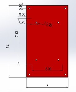
The previous top plate measures to be 7 cm width and 12 cm length in order to fit the PCB and the 3Dot board on it. Each hole on each corner will connect the bottom plate with spacers and screws.The team thought of the battery on the 3Dot board because it can produce amount of heat to the top plate, which could melt it.
Final top plate
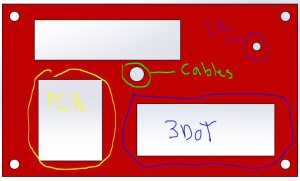
The final top plate is the same dimensions as the previous top plate. The only changes to it are making extrusion cuts in order to prevent the heat of the 3Dot board and PCB from touching the top plate. A hole is made so that the IR tube is screwed into it. Cables from the motor will go through the hole mentioned in the below figure. An extra extrusion cut is made to see the gears move for everyone to see.
3DoT David legs, femur and tibia design evolution:
Legs design evolution
Leg 1
As the team assembles the 3Dot David, connections that were made with the tibia and femur were blocking the movement of all the other legs. As a result of the tests that were made, the team decided to change the leg design to make sure there are no interferences with the movement.

Leg 2
By making it as one piece and centering the tibia, no interferences will be made on the movement. However, it could not be printed because the height of the tibia was too high at 6.8 cm.

Leg 3
By making separate pieces of the leg, which are the tibia and femur, 3D printing will make it easier because the parts have a flat surface. The extrusion cut was made for the connection of the screw at 0.265 centimeters. Super glue will be added to secure them in place as it walks on the floor.


Femur design evolution
Previous Femurs
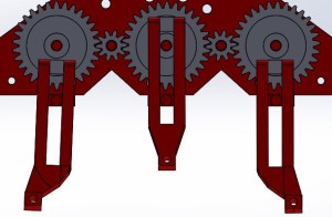
The previous femur had trouble stabilizing its weight as it walks. By attaching all the six femurs, it was not able to balance because of the 4 legs attached to the corner gears. However, this femur will be implemented into the middle gear of the gear train.

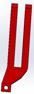
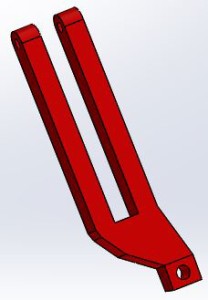
Adjusted femurs
With these two adjusted femurs, theoretically, the 3Dot David will not have trouble walking. The femurs would help it balance as it walks.
Implementing the femurs
By implementing the femurs into the bottom plate, the spider will balance itself, according to the figure below.
Tibia design evolution
Adjusted tibia
The tibia had to be adjusted by adding 1.5 centimeters to 5.3 centimeters of the previous tibia. That is because the gearbox on the bottom of the bottom plate was almost touching the surface. By adding it, 6.8 centimeters is the length of the tibia that will solve the issue.

Conclusion
As the team solved issues with the bottom plate, legs, and top plate by assembling and testing them, the design evolved in that process. Costs and time took a lot in the process. However, the evolution of the design is an experimental process towards finding the final design by making extrusion cuts to lessen the printing time as well as making the design beautiful and stabilizing the spider by adjusting the femurs and bottom plate.

