Electronic Design
By Chelsea Mediavilla (Electronics and Control)
In this post, the electronic design of the final printed circuit board is discussed. The Fritzing Diagram, breadboard prototype and Eagle schematic are summarized.
Table of Contents
Introduction
The Spring 2016 SPARCCS project centers around the integration of a dosimeter and a Single Event Upset (SEU) monitor on a single printed circuit board that communicates through RS-422. Each aspect of this board requires specific equipment to ensure functionality. The chosen dosimeter, an LN-712 Geiger-Müller tube operates off of high voltage, and thus requires a high voltage converter. The camera transmits information through a UART port, and the RS-422 requires UART transceivers.
LN-712 Geiger-Müller Tube
As discussed in the software design and IC trade off blog posts, the Geiger-Müller tube requires a high operating voltage. The transformer circuit on the SparkFun board left this high voltage section uncovered. As a safer and more compact alternative, the circuit was replaced with a DC to high voltage converter.
RS-422
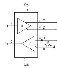
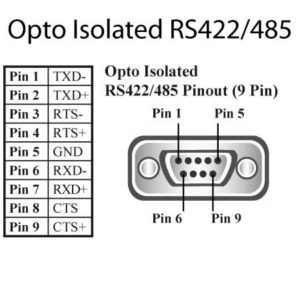
RS-422 is a technical standard commonly used in projects designed for space. Contrary to our initial thoughts, RS-422 is not compatible with a USB connection, and instead utilizes a DB9 port. The pinout for this standard requires the differential forms of RX (receiving), TX (transmitting), CTS (clear to send), and RTS (request to send). These differential lines are obtained through transceivers that split each signal. RX and CTS act are the data being transmitted from the micro controller, while it receives TX and RTS. The outputs of the transceivers connect to a DB9 connector according to the standard RS-422 pinout.
Fritzing Diagram
The Fritzing Diagram for this project was initially designed with the intention of testing the high voltage Geiger tube circuit and transceiver to DB9 connection. The module for the micro camera was created using the design of a pre-existing camera in the Fritzing diagram. Similar transceivers were already provided by the Fritzing program, so their pins were renamed for our purposes. Also, the ATmega32u4 micro controller was displayed w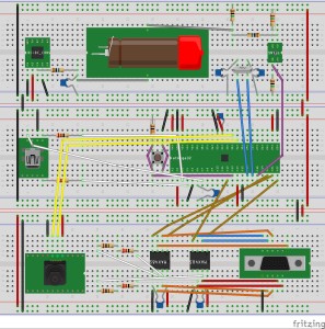 ith all of the necessary connections.
Unfortunately implementing this design was not possible for multiple reasons. After the high voltage converter was ordered, the shipment of the part was continuously delayed by the carrier. As a result, the part was not available for testing, and will also not arrive by the day of our final demonstration. The DB9 connector, USB connector, and transceivers were also unavailable at the time and thus the RS-422 connection could not be tested. Because we did not have access to the correct microcontroller at the time, a SparkFun Pro Micro was used in its place. A more accurate depiction of the Fritzing diagram would include the SparkFun Pro Micro and remove the DB9 and USB circuitry. If the arrival date had not been delayed the design would include the DC to high voltage converter.
Breadboard
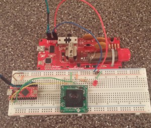
The breadboard prototype was extremely limited due to the reasons outlines above. Ultimately, the SparkFun Geiger Counter board had to be used for the high voltage circuit and Geiger tube. For our prototype, the SparkFun board was used as a rough equivalent to the top board in the Fritzing Diagram.
Schematic
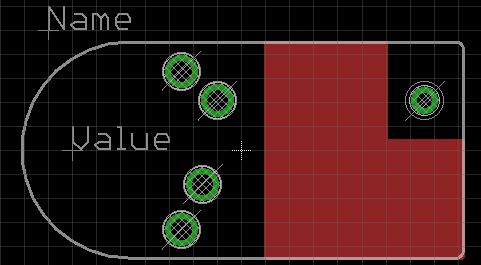
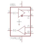
The schematic for the printed circuit board (PCB) was designed using EagleCAD. With the SparkFun Geiger Counter and the ATmega32u4 datasheet as references, I connected the Geiger tube to an interrupt and set the preliminary connections for the microcontroller (crystal, USB port, resistors, etc.). The PC-104 acts as the main source of power and thus connect to most of the devices. The Eagle CAD library is limited to commonly used parts, so the micro camera, DC to HV converter and transceivers required custom designs. The footprint of the camera was created using the measurements provided in the datasheet. The same process was followed for the high voltage converter using its datasheet. The red portion of the converter marks the area where traces should not be made due to the presence of high voltage. Similar models of the transceivers were included in the Eagle library and thus required little editing. The model was changed so that the pins were renamed and the supply voltage and ground pins were visible for connections. The three custom parts are provided below and included in the final schematic. This final schematic was passed on to the manufacturing engineer for board layout.
Conclusion
The Spring 2016 SPARCCS project was modeled using three designs: a Fritzing diagram, a breadboard prototype, and an Eagle schematic. The Fritzing diagram models an ideal version of the breadboard simulation that would have been used had all of the components been available. The eagle schematic is an accurate representation of the final design of the printed circuit board.
References
https://www.sparkfun.com/products/11345
http://www.atmel.com/images/atmel-7766-8-bit-avr-atmega16u4-32u4_datasheet.pdf

