Fall 2016 Solar Panels: Folding Mechanism Trade-Off Study
By Ridwan Maassarani (Design & Manufacturing)
Edited and Approved By Inna Echual (Project Manager)
Folding Mechanisms Considered
Objective: One of the most important components of our project is to define the folding mechanism that will allow us to achieve the cocooning requirement. This study will showcase the mechanisms we considered and which of the ones research was chosen.
Rack and Pinion
Video 1: Rack and Pinion Folding Mechanism
This idea was brought up through a YouTube search on “folding mechanisms,” resulting in the rack and pinion method in the video above. The folding is accomplished by sliding a rack back and forth and spinning a spur gear placed at the hinges of the panels. This configuration was created to fold t-shirts but I found this video to be very helpful.
For doing this method, the rack would have to be suspended from underneath the panel because doing a two-layered panel configuration like the video would be unfeasible as it would result in more materials, adding cost and weight. Taking those factors into account, it was additionally determined that is method is not the best for folding our panels since having the rack be suspended underneath could prevent the side panels from going -15° (for example) when the panels articulate to track the sun.
However, this video inspired us to consider attaching a gear to the pin of a hinge and to consider a gearing mechanism to do the folding of the panels.
Linear Actuator
Video 2: Linear Actuator Folding Mechanism
This method of using a linear actuator was both found by doing the same YouTube search and as suggested by Professor Hill. Though the linear actuator would provide enough force to push open our panels despite its weight, we had many concerns:
- An obvious placement of the actuator would be on the stationary front side panel and on the side closest to the base (see Figure 1). This placement would cause two problems: (a) we would be losing valuable real estate for putting our solar cells, space that we need to achieve power generation for charging the battery. And (b) putting the actuator on the top will prevent our back side panel from completely closing onto the back front panel, which also brings up the problem when folding the two onto the base for the cocooning.
- To fix the problems brought up in (1) above, we considered placing two pads on the side of the front panel furthest from the base panel (see Figure 2). Our problem with this placement is that we assumed putting pads there would dissatisfy with the Level 1 Requirement of having the panels be identical to that of the Opportunity and Spirit rovers. The placement there would also be not ideal as since the actuator is on the other side of the side panel, it could interfere with the rover’s overall center of mass.
- We also considered placing the actuator underneath the panels but we had difficult time finding a mechanical configuration to encompass the 0° to 180° range of the panel folding.
Therefore, we determined that this method was not the best and we continued to research further on folding mechanisms.
Bevel Gear
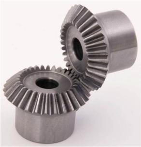
Figure 3: Bevel Gear
Through we are not considering rack and pinion method for folding, we were inspired by the gear to incorporate a bevel gear into the mechanism to lift the panels into position. One bevel gear would be fixed to a rod extending from piano hinge and that pin of the hinge will be welded to one side of the hinge on the panel that needs to be lifted.
The main concern is the panel could not be kept at a specified angle and the motors would have to be constantly turned on to hold the panel at that angle. After the Iterative design process and additional research, the worm gear was considered for its self-locking feature.
Worm Gear
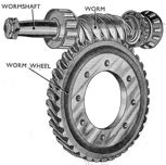
Figure 4: Worm Gear
The worm gears are considered because of power transfer due to the effectiveness of the two gears meshing. One appealing feature is that they are self-locking, meaning that the gear cannot drive the worm. For example, when the weight of the panels exerts torque, the motor is not affected; if the panels are going from 90° to 180° there won’t be load exerting torque on the stepper motor. Another feature is that they occupy less space which would declutter the design and reduce overall mass.
The most important advantage is that they are known for being used for speed reduction and increasing torque. This will be extremely helpful when doing a lifting action for our sun articulation.
Mounting the Stepper Motor
A custom bracket shall be designed to allow to mount the stepper motor low to the ground.
Torque
Take the right back panel for example:
Weight of panel on SolidWorks using 6061-T6 Aluminum = 165 grams
Distance
For safe measure a weight of 250 grams will be used.
So, a motor with a torque of 23 oz.in or higher will in theory be able to lift the right pack panel.
Gear Ratio
As stated earlier, one of the advantages of worm gear is having higher gear ratios. For this example, a 30:1 gear ratio will be examined.
Motor – NEMA 17-size hybrid stepping motor with a torque of 44 oz.in
Motor Torque x gear ratio = torque at the hinge
This is more than enough to be able to lift the panels.
Figure 5: Lever Arm from Axis of Rotation