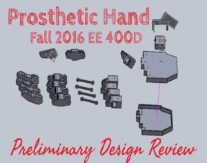
Fall 2016 Prosthetic Hand – Preliminary Design Review
Project Manager – Kimberly Younger
Mission, Systems, and Test Engineer – Mia Lai
Electronics and Control Engineer – Younis Al-Kharusi
Design and Manufacturing Engineer – Wilson Mach
Table of Contents
Mission Profile
By Project Manager – Kimberly Younger
As defined by the customer, the project mission of the prosthetic system shall allow a soldier requiring a prosthetic arm to eat a McDonald’s Quarter Pounder with Cheese meal. The prosthetic system will be designed to support the large community of wounded soldiers needing a prosthetic arm. While a fixture may be used to hold the meal, the other arm may not be used to feed the hungry soldier. [1] In order to accomplish this goal, the prosthetic system will be manufactured as two separate entities, including a prosthetic arm and a prosthetic hand. The two entities will be able to attach and function as a single unit.
Research References
[1] EE 400D F’16 Project Objectives and Mission Profile by Gary Hill
http://web.csulb.edu/~hill/ee400d/F’16%20Project%20Objectives%20and%20Mission%20Profile.pdf
Program Objectives
By Project Manager – Kimberly Younger
In order to achieve the mission profile, generalized program objectives needed to be qualified. The program objective is to use a part of the body that is not the hand to effectively control a prosthetic hand. The control would include wrist rotation ability and finger grasping ability. In conjunction with a Prosthetic Arm, the system would be able to feed someone a fast food meal without an allotted amount of time, being 20 minutes.
Requirements
Level 1 Project Requirements
By Project Manager – Kimberly Younger
By Mission, Systems, and Test Engineer – Mia Lai
R1 – The Prosthetic Hand will be a functional component of the Prosthetic System by having capabilities to attach and work with the Prosthetic Arm, as defined in the mission profile, provided by the customer.
R2 – The Prosthetic Hand will be humanoid.
R3 – The Prosthetic Hand shall feed a person a McDonald’s Quarter Pounder with Cheese meal (as defined by the McDonald’s website) within twenty minutes of first picking up the meal.
R4 – The Prosthetic Hand shall be capable of picking up a medium drink/malt, Quarter Pounder with Cheese, and bundles of French fries (1-10 fries per bundle) without breaking the cup/food item.
R5 – The Prosthetic Hand movements shall be controlled without the use of another hand.
R6 – The total cost of the project shall not exceed 400 USD.
R7 – The project shall be completed on or before the end of the CSULB Fall 2016 Semester, which is 12/22/2016, as defined by the CSULB Academic Calendar.
Level 2 System and Subsystem Requirements
By Mission, Systems, and Test Engineer – Mia Lai
R4 – The Prosthetic Hand shall be capable of picking up a medium drink/malt, Quarter Pounder with Cheese, and bundles of French fries (1-10 fries per bundle) without breaking the cup/food item.
- R4.1 – In order to keep food from slipping out of the hand, the hand shall be capable of providing a minimal grip force of 11.8 N.
- R4.1.1 – In order to provide a grip force of 11.8 N, the Motors shall be capable of providing a torque of 0.133
- R4.2 – In order to pick food up from a table, the Wrist of Prosthetic Hand shall have ability to rotate 90 degree up and 90 degree down from its neutral position.
- R4.2.1 – The stepper motor at the wrist of the hand shall be capable of providing a minimal torque of 0.0075 Nm to rotate the hand.
- R4.3 – The force sensors of the Prosthetic Hand shall be sensitive to an applied force range of 0-11.8 N. This sensing force range is based on the calculation of maximum grip force of the hand described in requirement R4.1.
- R4.4 – In order for the amputee to be able to wear the prosthetic hand, the mass of the entire hand, not including power sources or external devices, should be between 350g and 615g.
Appendices
Appendix A – Grip Force Calculation
By Mission, Systems, and Test Engineer – Mia Lai
R4.1 – In order to keep food from slipping out of the hand, the hand shall be capable of providing a minimal grip force of 11.8 N.
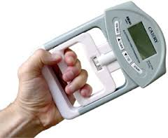
Verification: The grip force of the hand can be verified by using a Hand Grip Dynamometer. (Shown below)
Figure 1: Hand Grip Dynamometer
Assumption: Acceleration of the hand is not significant and can be neglected.
Friction Force: F=µN
- Where µ is the coefficient of static friction
- Where N is the Normal Force or Grip Force
To ensure the cup does not slip
- F must be greater than or equal to the weight of the cup
- µ * Grip Force must be greater than or equal to the weight
- Therefore, grip force must be greater than or equal to weight/µ
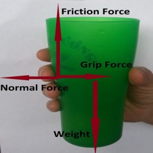
A free body diagram is shown below.
Figure 2: Cup Free Body Diagram
Worst case scenario: Hand must pick up 600 gram cup of soft drink.
Grip force = Weight/µ [2]
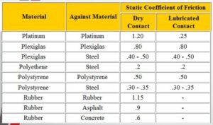
According to the Coeffiecient of Friction Table shown here [1], the µ for plastic-plastic is 0.5.
Figure 3: Friction Coefficient Table
Force = mass * acceleration (gravity)
= 0.600 kg * 9.81 meters/(sec)^2 = 5.8 N
5.9 N/µ= 5.9 N/0.5 = 11.8 N
The minimal required grip force is 11.8 Newtons.
Appendix B – Robotic Gripper Torque Requirements
By Mission, Systems, and Test Engineer – Mia Lai
R4.1.1 In order to provide a grip force of 11.8 N, the motors shall be capable of providing a torque of 0.133 Nm.
Verification: The torque of a motor will be verified by attaching an object at the end of the string and the other end of the string is tied to the motor shaft. When the motor turns, the shaft will rotate and lift the object up. The motor torque is calculated by multiplying the weight of the object with the radius of winding.(Shown below)
Figure 4: Motor Torque Experiment
Assumption: Acceleration of the hand is not significant and can be neglected.
Required Torque = Required Grip Force * Moment Arm Length
- T=F*r*safety factor [3]
- Where F is the hand grip force for holding a 600 g cup of soft drink = 11.8 Newtons
- Where r is the radius of the 22 ounce cup = 37.5 mm
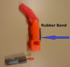
The safety factor is 1.5. In our design, there is a rubber band at the back of each finger. These rubber bands act as springs to pull the finger back to the original position.
- According to a UBC physics experiment [4], the pulling force of rubber bands is between 0.5 N and 4.5 N.
- The actual grip force provided by the hand is 1.5*required grip force.
Required Torque to grip the cup:
- T=F*r*safety factor=11.8 N * 00375 m * 1.5=0.66 N-m
Required Torque for each Finger Motor:
- Required Motor Torque = T/number of fingers=0.66/5=0.133 N-m
Figure 5: Showing of Rubber Band
Appendix C – Inertia Moment and Torque Calculation
By Mission, Systems, and Test Engineer – Mia Lai
R4.2.1 – The stepper motor at the wrist of the hand shall be capable of providing a minimal torque of 0.0075 Nm to rotate the hand.
Verification: This requirement can be verified by using the Motor Torque Experiment method mentioned in R4.1.1.
Assumptions:
- The hand shape is hollow and cylinderical. The radius of the cylinder is half of the width of the hand.
- The hand will accelerate from 0 to 280 degree/second in one second. This speed is obtained from the suggested speed for a prosthetic device. [1]
Note:
- The torque to hold the hand out horizontally and the torque to rotate the hand at the wrist base are different.
Torque when acting at a pivot point:
T=I*α
- Where α is the angular acceleration
- α=280 degrees/sec^2 = 4.89 rad/sec^2
- where I is the moment of inertia of a cylinder
- I=m*(R^2)/2 = 0.0015 kg*(m^2)
The worst case scenario for the torque is when the hand rotates while holding a drink:
Total Mass:
- M= mass of hand + mass of food = 615 g + 600 g = 1215 g
- R = width of palm/2 = 0.090/2 = 0.045 m
- Palm width in our design is currently 90 mm
Minimal torque for rotation of the wrist:
- T = 0.0015 kg*(m^2)*4.89 rad/sec^2= 0.005 N-m
Minimal torque required for stepper motor:
- Trequired = T + 50% uncertainty = 0.005 N-m + 0.0025 N-m = 0.0075 N-m
Figure 6: Hand Flexion
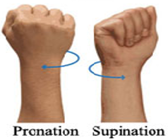
Figure 7: Hand Pronation and Supination
Requirements References
[1] Coefficient of Friction Table Chart
https://www.engineersedge.com/coeffients_of_friction.htm
[2] Robotic Grip Force
http://blog.robotiq.com/bid/69524/Robotic-End-Effectors-Payload-vs-Grip-Force
[3] Robotic Gripper Torque
http://www.grippers.com/size.htm
[4] UBC Rubber Band Stretch Force Experiment
http://c21.phas.ubc.ca/sites/default/files/rubber_band_write_up.pdf
[5] Medium Cup Size
[6] Robot Arm Inertia moment and torque tutorial
http://www.robotshop.com/blog/en/robot-arm-torque-tutorial-7152
[7] Suggested Speed of Prosthetic Device
Design Innovation – Creativity Presentation
Essential Problems
By Project Manager – Kimberly Younger
Problem #1: How will the ‘Prosthetic Hand’ be controlled?
- EMG signals?
- Computer Application?
- Remote Control?
- Flex Sensors?
Problem #2: How can it be ensured that grip will be sufficient but not too strong as to squish the food?
- Force needs to be just sufficient enough for each item.
Problem #3: By what mechanism will the wrist turn?
- Needs to turn clockwise and counterclockwise without harming connection to arm
Problem #4: How will the ‘Prosthetic Hand’ be connected to the ‘Prosthetic Arm’ to produce a ‘Prosthetic System’?
- Connection cannot hinder wrist movement
- Needs a Locking Mechanism
- Requires sufficient space for connection
Problem #5: How will the ‘Prosthetic Hand’ be powered?
- Power could be shared
- Wires should not extend outside of the hand/arm
Proposed Solutions: Problem #1
By Project Manager – Kimberly Younger
Problem: How will the ‘Prosthetic Hand’ be controlled?
Method: Duncker Diagram
Idea: Rather than basing our design with a target audience of amputees, we would like to have a target audience of paralyzed people, people suffering from ALS, etc. This way, they have movement in some part of their body to help control the hand, via remote control. In addition, it broadens the market reach for the product.
Questions: Would the remote control be able to be controlled by different parts of the body (ex. Hand, foot, face) to accommodate different people?’
Experiment: Connect a breadboard to an Arduino, then use Arduino IDE to program a Wii Nun chuck and use PID to control motor. Ensure that the Nun chuck is can be used by parts of the body that aren’t the hand (such as a foot or mouth).
By Electronics and Control Engineer – Sara Gonzalez
Problem: How will the ‘Prosthetic Hand’ be controlled?
Method: Brainwriting
Idea: Use flex sensors from one hand to control the other. If someone has control of one hand, but lacks control or lifting power in both arms, he or she may use the one hand to control the bionic one.
Questions: Can pressure be assessed using this method? What would the response time be on the bionic hand after the flex sensor’s signal was sent? Would motions have to be separated as to not “confuse” the hand?
Experiment: Experiment with one flex sensor to one “finger”. In a rapid prototype, ensure that that the flex sensor would be able to control the finger, measure response time, and test what happens when resistance is added to the “finger”.
Proposed Solutions: Problem #2
By Mission, Systems, and Test Engineer – Mia Lai
Problem: How can it be ensured that grip will be sufficient but not too strong as to squish the food?
Method: Brainwriting
Idea: Use a servo that has restricted range of motion. The user is involved in the gripping process and stops the finger from squishing the food.
Questions: How much of a lag will occur between person wanting the grip to stop and the system stopping it? Will this cause the food to be squished in the meantime?
Experiment: Attach “fingers” to a servo motor(s) and attempt to lift items with the “fingers”. Demonstrate if the servos are sufficiently sturdy and precise to handle lifting a burger/fries/shake.
By Mission, Systems, and Test Engineer – Mia Lai
Problem: How can it be ensured that grip will be sufficient but not too strong as to squish the food?
Method: Attribute Listing
Idea: Add rubber to the fingertips, give to help ensure that the food does not fall out of the fingers.
Questions: How thick of rubber would lead to the best grip? Should there be divots in the grip pads to increase surface area for grip?
Experiment: Purchase or create finger gloves (demonstrated in the picture) using different materials or types of rubber. Have people try eating with the finger gloves and document which one has the best grip and causes the least food slippage.
Systems/Subsystems Design
Product Breakdown Structure
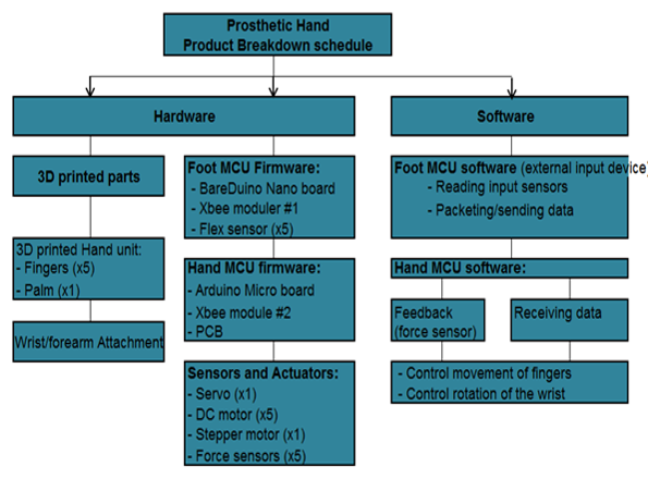
Figure 8: Product Breakdown Structure
By Missions, System, and Test Engineer – Mia Lai
Note that the Prosthetic Hand Product Breakdown Structure does not include power because the Prosthetic Hand and Arm will share a single power source.
Software Block Diagram
Figure 9: Software Block Diagram
By Electronics and Control Engineer – Younis Al-Kharusi
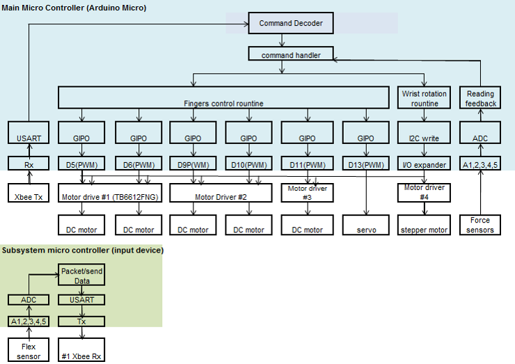
The software models include the following:
- I2C Write Module
- Input: 16 bit digital I/O expander
- Output: N/A
- Finger Control Module
- Input: Analog Signal Reading (Flex Sensors)
- Output: DC Motors/Servos
- Wrist Rotation Module
- Input: Analo Signal Reading (Flex Sensors)
- Output: Stepper Motor
- Reading Feedback Module
- Input: Pressure Sensors
- Output: N/A
Electronics System Block Diagram
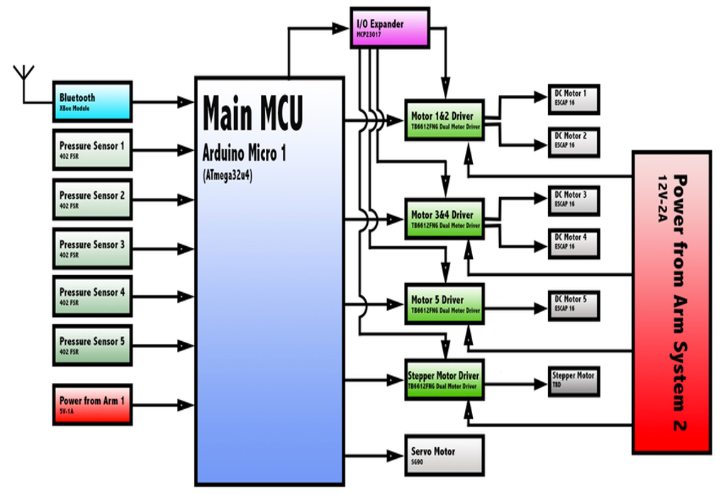
Figure 10: Main System Block Diagram
By Electronics and Control Engineer – Younis Al-Kharusi
Figure 11: Subsystem Block Diagram
By Electronics and Control Engineer – Younis Al-Kharusi
Interface Matrices
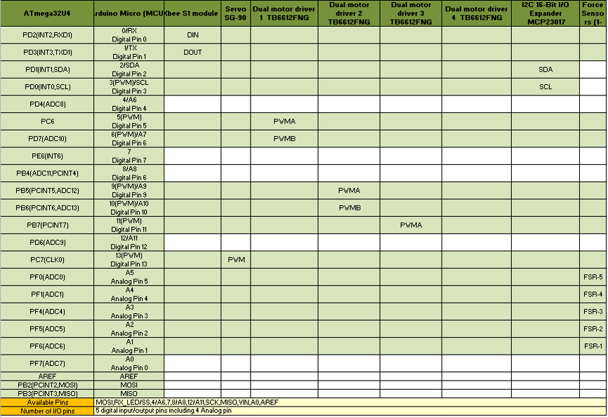
Figure 12: Main Interface Matrix
By Electronics and Control Engineer – Younis Al-Kharusi
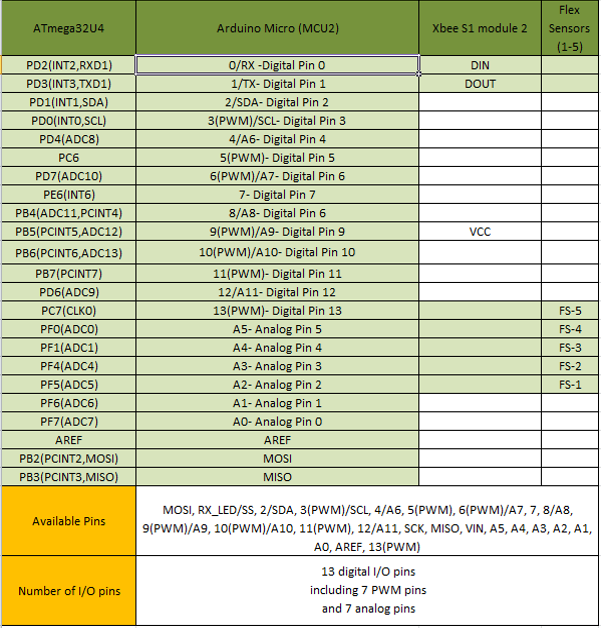
Figure 13: Subsystem Interface Matrix
By Electronics and Control Engineer – Younis Al-Kharusi
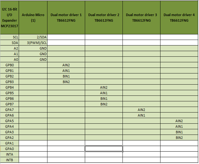
Figure 14: I2C Interface Matrix
By Electronics and Control Engineer – Younis Al-Kharusi
Fritzing Diagrams
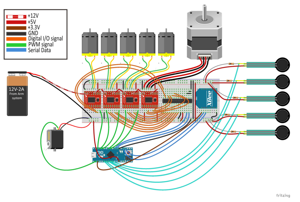
Figure 15: Main System Fritzing Diagram
By Electronics and Control Engineer – Younis Al-Kharusi
Figure 16: Subsystem Fritzing Diagram
By Electronics and Control Engineer – Younis Al-Kharusi
Preliminary Prosthetic System Interface Matrix
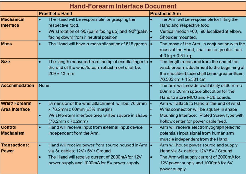
Figure 17: Preliminary Interface Control Matrix
By Mission, Systems, and Test Engineer – Mia Lai
Potential Problems:
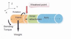
- Rotation of the hand at the wrist base weakens the connection between the two systems.
- The estimated bending toque at the wrist base is 1.23 NM
- From T=Mass(hand+food)*Palm Length
- =[(0.600 kg+0.615 kg)9.8]*0.104=1.23 N-m
- From T=Mass(hand+food)*Palm Length
- The hand has the potential of breaking off when picking up a 600 gram cup of soft drink.
- A request has been submitted to simulate/model this interface to test the strength of the hand at the wrist base.
Figure 18: Interface Emulation
By Mission, Systems, and Test Engineer – Mia Lai
Design and Unique Tasks
By Project Manager – Kimberly Younger
- Completed Tasks
- Initial Fritzing Diagram
- Flex Sensor Control of One Finger
- Hand Modeling
- Finger Modeling
- Wrist Modeling
- Begin 3D Printing
- Planned Tasks
- Trade Off Studies
- Motors (Servos vs. DC)
- Ball Bearings vs. Screws on Joints
- Hand Materials
- Rapid Prototypes
- Grasping Motion
- Stepper Motor for Wrist
- Analog Input Signal Verification
- Shared Power System
- Wireless Communication
- Trade Off Studies
Mechanical System Design
Design Overview
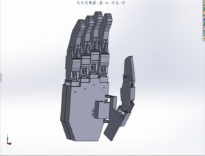
Figure 19: Hand Design in SolidWorks
By Design and Manufacturing Engineer -Wilson Mach
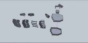
Figure 20: Exploded View Hand Design in SolidWorks
By Design and Manufacturing Engineer -Wilson Mach
Modeling
Figure 21: Exploded View Finger Joint in SolidWorks
By Design and Manufacturing Engineer -Wilson Mach
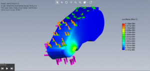
Figure 22: Finger Stress Test in SolidWorks
By Design and Manufacturing Engineer -Wilson Mach
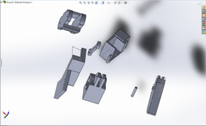
Figure 23: Exploded View Finger in SolidWorks (View 1)
By Design and Manufacturing Engineer -Wilson Mach
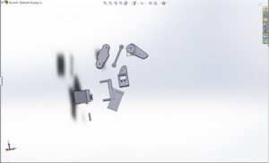
Figure 24: Exploded View Finger in SolidWorks (View 2)
By Design and Manufacturing Engineer -Wilson Mach
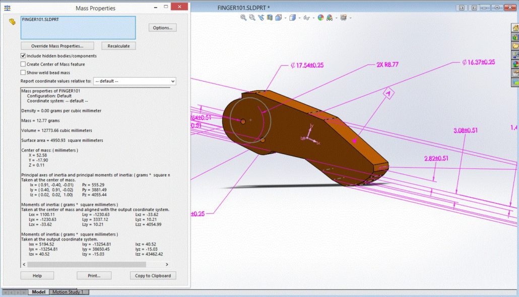
Figure 25: Finger Mass Properties in Solid Works
By Design and Manufacturing Engineer – Wilson Mach
Figure 26: Wrist Model
By Design and Manufacturing Engineer -Wilson Mach
Figure 27: Wrist Model Sketches
By Design and Manufacturing Engineer -Wilson Mach
Mechanical System Design References
[1] http://www.instructables.com/id/Tact-Low-cost-Advanced-Prosthetic-Hand/
[2] https://grabcad.com/questions/how-do-i-convert-stl-graphics-to-a-solid-model
[4] https://forum.solidworks.com/thread/44730
[5] https://www.youtube.com/watch?v=TogMwMSSUPE
[6] https://vimeo.com/24805708
[7] https://www.youtube.com/watch?v=85w5xrllW2k&index=44&list=PL2qTZTUgMJPDT2uIFu1-UMW-eRxk_stcL
[8] Book: Solidworks 2016, A Power Guide for Beginners and Intermediate Users 3rd edition
Project Status and Schedule
Work Breakdown Structure
Figure 28: Work Breakdown Structure
By Project Manager – Kimberly Younger
Project Schedule
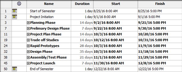
Figure 29: Top Level Schedule
By Project Manager – Kimberly Younger
The schedule is broken up into project phases, with each phase having underlying sub level tasks.
Figure 30: Critical Path
By Project Manager – Kimberly Younger
The critical path follows the two design phases, test phase, and project launch. The most crucial and potentially volatile part of this path is the integrated testing that must be done within the Assembly/Test phase.
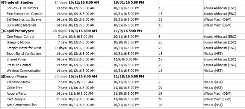
Figure 31: Sublevel Tasks
By Project Manager – Kimberly Younger
Burn Down
Figure 32: Burn Down Chart
By Project Manager – Kimberly Younger
This burn down chart demonstrates the timeline of the project in terms of percentages and tasks left. The project percent completion indicates past as well as projected completion rates according to the project schedule.
Resource Allocation Reports
Mass Report
Figure 33: Mass Allocation Report
By Mission, Systems, and Test Engineer – Mia Lai
Cost Report
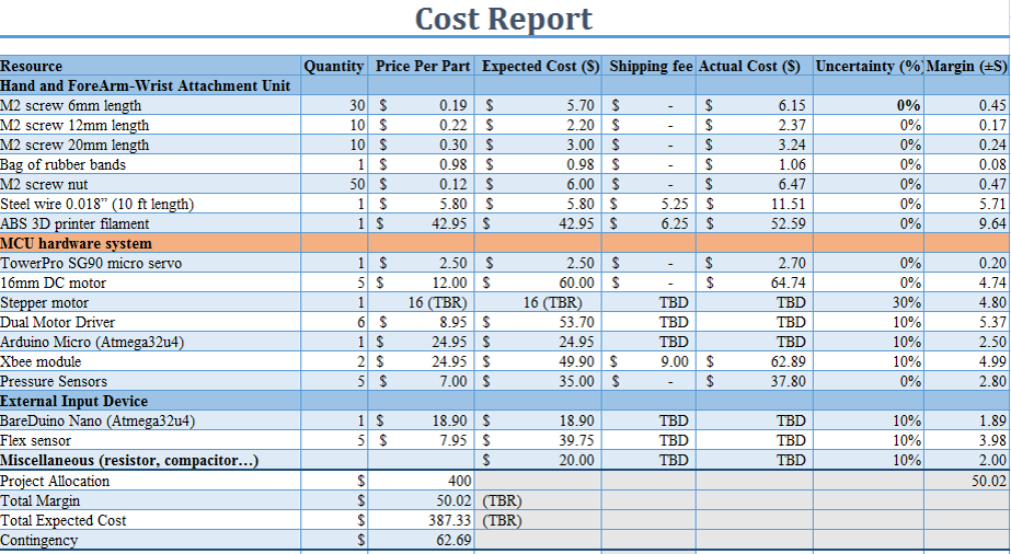
Figure 34: Cost Allocation Report
By Mission, Systems, and Test Engineer – Mia Lai

