Fall 2016 Biped – Updated System/Software Block Diagrams
Updated Diagrams
By: Brandon Perez (Missions, Systems, and Test Engineer)
Approved by: Ijya Karki (Project Manager)
Table of Contents
Introduction
Included is the post CDR updated system and software block diagrams.
System Block Diagram
This is Biped’s most up-to-date System Block Diagram. Start with the 3-Dot board block diagram provided in the 3-Dot folder.
On the bottom left, you can see the Arxterra App on the Android Mobile Device communicating with the Bluetooth v4.0 BLE Transceiver on the 3Dot Board.
On the top left, we have a 7.4V Li-Ion Battery connected to an LDO 5V Regulator which then connects to the external battery connector of the 3Dot board.
On the right side of the diagram you can see our DC Motor connected to Motor A pins of the 3Dot board. Servo (arms) and Servo (body) used for shifting center of mass are attached at the servo pins of the 3Dot board.
On the bottom right, we have three sensors (IMU, Color Sensor, and Rotary Sensor) connecting directly onto the I2C Peripheral Interface pins (PWR, GND, SCL, SDA) of the 3Dot board. We also have an I2C GPIO Expander connecting the I2C Peripheral Interface to help interface with our remaining devices: Left Ankle Servo, Right Ankle Servo, and RGB LED.
Changes From Previous Design
What did we change from our previous design?
Now using one motor to control the walking movement to closely resemble the Theo-Jansen walking mechanism. A rotary sensor is being used instead of the optical sensor for ease of implementation and programming.
Possible Future Changes
What may be subject to change?
Servos being used to control the Center of mass shifting may be removed due to our mechanical design shifting the center of mass entirely with the help of our crankshaft turning the ankles. We may not need the body servo to shift the center of mass of the system when walking on inclines since we can mechanically design our system to be stable for varying angles. If that’s the case, we would be left with an RGB LED on the GPIO expander. However completely removing the servo to shift the center of mass is unlikely. A better solution would be to use both the mechanical design and a servo to shift the center of gravity (similar to the Theo-Jansen Biped).
System Software Block Diagram
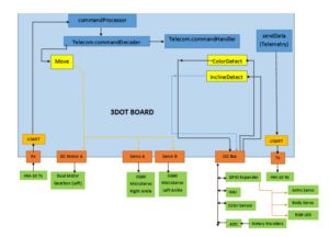
This is Biped’s most up-to-date System Software Block Diagram.
Changes from Previous Design
What has changed?
Our 2nd DC Motor has been taken out so our software has now changed. We are possibly not going to add any custom commands since we can ultimately utilize the parameters from sent to the predefined Move command and modify them to control our DC motor, and our 2 servos used for turning. The this will work is explained in the Arxterra Control Panel Blog post.


