Fall 2016 Biped – Updated Motor Study
By: Alan Valles (Electronics and Control)
Approved by: Ijya Karki (Project Manager)
Table of Contents
Introduction:
The purpose of this document is to further analyze the constraints for our DC motor. This motor will convert drive the crank that our linkage based leg system will use to walk.
Analysis/Data:
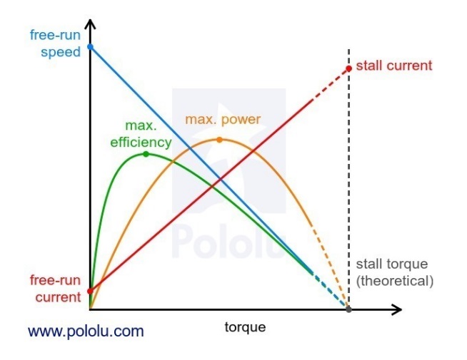
One simple design is to use a gearbox to change the output torque ratio. There are four main characteristics of a DC motor that are of the most concern. There are the electrical properties, such as the nameplate operating voltage, and current drawn by the motor under various physical loads. There are also the physical properties of the motor such as speed and torque load.

Since Torque = force * lever arm and sin operator of the angle between them, we can conclude that the maximum torque will be at an angle of 90 degrees. Lever arm data will be gathered from meeting tomorrow along with
F= m*acceleration = 250g * 9.8 = 2.45 newtons
T = F*l = ____NM(lever arm length TBD)
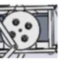
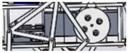
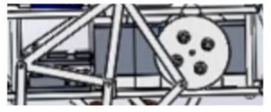
Output torque of motor at stall rating shown to be .004 NM. However, the gear ratio is used to increase torque and decrease rated speed which is 11500 RPM.
The Results in the last blog post still stand and in order to meet scheduling requirements, we will utilize the existing gearbox which is the Tamiya XXXX.
Conclusion:
Thus, the Pololu 1117 130 Motor with the Tamiya gearbox will be used to meet the required torque and power requirements.
References:
http://www.electrical4u.com/dc-motor-or-direct-current-motor/
https://en.wikipedia.org/wiki/Torque
http://uav.ece.nus.edu.sg/~bmchen/courses/EG1108_DCmotors.pdf