Fall 2016 Solar Panels: Product Breakdown Structure Update
By Stephan Khamis (Mission, Systems, and Test)
Approved by Inna Echual (Project Manager)
Table of Contents
Introduction
This blog post contains our most up-to-date product breakdown structure for the Solar Panel system of the Pathfinder project. Within this blog post you will learn about the changes we have made since the critical design review (CDR) to update this document.
Updated Product Breakdown Structure

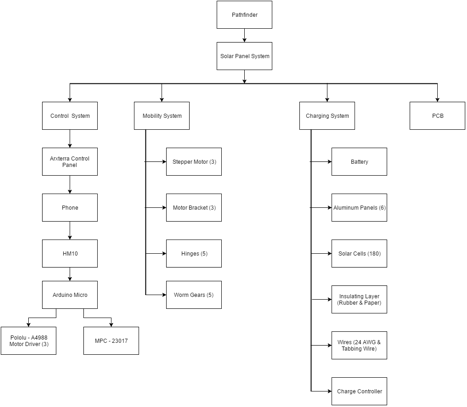
Figure 1: Updated Product Breakdown Structure
Due to feedback we got during the CDR presentation, our Product Breakdown Structure was updated to reflect our project. This Product Breakdown structure states all the item’s that we have used to create our Solar Panels. This flow down structure is helpful as it explains where the items are used for. I will also state why we decided to use some of these items.
As stated before, this is a flow down diagram. The Pathfinder is the main overall system and a part of that, is the Solar Panel (in which we care about). Within the Solar Panel system, you’ll find four main systems that were used to help complete this project: Control System, Mobility System, Charging System, and PCB.
Control System
The main idea for the Control System is to be able to control our Solar Panels—in other words, we should be able send commands and receive telemetry data. The first main product in which we are utilizing is Professor Hill’s Arxterra Control Panel. The corresponding app will be used so the joint Pathfinder group will be using an android phone. Most of the other projects used a 3Dot board which has Bluetooth LTE built into it. The Android Phone uses an HM-10 Bluetooth connection.
Three Pololu-A4988 Motor Drivers will be attached to our Arduino Micro, which will be used to control our stepper motors, and an MPC-23017 chip to make room on the Micro for our reed sensors. These reed sensors will stop the stepper motors and prevent the panels from overfolding and hit/damage the adjacent panel.
Mobility System
Within our mobility system, we will be using stepper motors (3), motor brackets (3), hinges (5), worm gears (5). These products are key to satisfying our cocooning mechanism. The stepper motors will be used to control the three folds that we have going on in our cocooning mechanism. The motor brackets will be used to connect our motors to the aluminum panels. The hinges will be used to fold the panels together. And the worm gears are also used in conjunction of our motors and hinges. We chose the hinges because it provided a low input, high output torque.
Charging System
The charging sufficient is the key to satisfying our mission profile, which is to have the Pathfinder be self-sufficient. The products within this system are as follows: 12-V 7000-mAh Lead Acid Battery, aluminum panels (6), solar cells (181), rubber insolation layer, sticker paper cavities, 24 AWG wires, tabbing wire, and charge controller. We decided to salvage and use the battery from the previous semester because it was still in great shape. One of the main requirements was to have our solar panels represent the form factor of the Spirit & Opportunity rovers. The two aforementioned rovers consists of six differently shaped panels. This leads to why we chose 39 mm x 39 mm polycrystalline solar cells. Not only are polycrystalline cells efficient but these were small enough to help us complete the form factor of the Spirit & Opportunity rovers. We also added an insulating layer and acrylic plating to protect the environment from the elements when it undergoes its mission. The cells were connected together using tabbing wire. A concern of charging a battery is allowing more voltage which can destroy the battery, so we decided to counter this with a charge controller that will not allow the voltage going into the battery to exceed 12-V.
PCB
We used a custom PCB board because essentially, it’s clean and small. This will help save us space within the electrical box that we shared with the Chassis group
Future Updates
As of now, we are not planning on updating our PBS. But, I may suggest for the next semester to be wise about the sizing and solar cells they choose to use. Some are very fragile and will break more often than not when soldering. They also don’t output the stated output on the website. It’s very unlikely it will ever hit those perfect conditions. I suggest using bigger solar cells, because at the end of the day, it’s best to complete the mission of charging a battery no matter what it looks like.