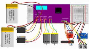
Fall 2016 Velociraptor (W): Fritzing Diagram
By: Taylor Farr (Electronics and Controls)
Approved By:
– Lam Nguyen (Project Manager)
– Ryan Daly (Division Manager for Electronics & Controls)
Table of Contents
Requirements
- The velociraptor shall utilize a printable circuit board (PCB).
- The velociraptor shall use a 3DoT board library and utilize I2C to communicate with sensors, A/D converter, and GPIO.
Introduction
In order to design a PCB that will be placed on top of the 3DotBoard, several drafts will be used before we find our final design. The Fritzing software will be used to design the PCB. It will also help us see where the necessary connections to be mad will be. This will help our systems engineer route the cable tree.

Diagram 1: Fritzing Diagram
In the center of Diagram 1 is a model of the 3dot board modeled by Alan Valles (biped E&C Wednesday). The 3dot board has an internal battery connection, an external battery connection, two servo headers, two motor connectors, and a female connector for the external PCB. For our initial design, we have two external batteries to be used for power and as weights for the head and tail. It is also seen that there will be two servos. One servo is to control the movement of the head and tail. The other servo was to be used to control the linear actuators which would change the linkage that controls the leg movement. 2 dc motors are seen to be used to drive the legs. For the I2C connection, everything here will be on the PCB. The I2C pins have 4 pins. One for power, one for ground, one for serial clock, and the last one for serial data. On the data sheet for each device, we can find where all the matching connections are. The red device is the IMU that we will use. It essentially requires to be connected to Vcc, ground, serial clock, and serial data. This is the same case for the A/D converter which is the blue device on the bottom right corner of the figure. Connected to the A/D converter is the two rotary encoders. These require to be connected to power and ground. The signal from those are connected to the inputs of the A/D converter. The final unit on our PCB is the GPIO port. The GPIO port is I2C compatible, and it is used to connect to the stepper motors. They will act as outputs that will drive tiny stepper motors.
Conclusion
Now that the Fritzing design is complete, we have a better understanding of what our PCB design will be like as well as the wiring of the system. All of the components that will be on the PCB are I2C compatible, so there is no problem.
