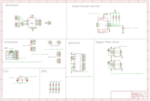
Fall 2016 Velociraptor: EagleCAD schematic
By Taylor Farr (Electronics and Control)
Approved By:
– Lam Nguyen (Project Manager)
– Ryan Daly (Division Manager for Electronics and Control)
Table of Contents
Requirements
L1 – 9: The velociraptor shall utilize a printable circuit board (PCB).
L1 – 10: The velociraptor shall use a 3DoT board library and utilize I2C to communicate with sensors, A/D converter, and GPIO.
Introduction
After the Fritzing design is complete an EagleCAD schematic has to be designed to create a PCB and move the project forward. EagleCAD is a software program that allows the user to place components on the board, and wire all the connections properly. Pins such as I2C pins can be connected across the network.
Figure 1: Eagle Schematic
Here, all of the components are seen with all of the connections visualized. In the top corner is the 3dot board. The external battery connection is connected to the output of the LDO (more on this later). The two servos and two motors are connected to the 3dot board. On the top right is the analog to digital converter. It is wired correctly according to the datasheet. It allows for four inputs. Two inputs will be used for each rotary encoder. On the middle left contains all of the connections. The female connectors for the IMU are on the left. To the right of that is the connections for the rotary encoders. The connections for the stepper motors are on the right. These connections connect to the stepper motor driver that is on the right. The stepper motor driver is connected to the GPIO expander located in the middle on the bottom. On the bottom left, the LDO is found. The external batteries that will be on the head and tail are going to be inputs to the LDO. The LDO regulates the output down to 5 volts and 1.5 amps. The connects to the external battery connector on the 3dot board in order to drive the servos at 5 volts. To the right of the LDO are some light emitting diodes to show that the PCB is working.
Conclusion
The completed fritzing diagram and the Eagle schematic pushed our final design closer to the completed product. We now have a concrete version of our schematic. This is then sent to the manufacturing engineer to order the external PCB layout.

