Fall 2016 Solar Panels: Mechanical Design *
By Ridwan Maassarani (Design and Manufacturing)
Approved by Inna Echual (Project Manager)
As a requirement, solar panels had to be manufactured that is of the same form factor as the spirit and opportunity mars rovers that were designed by NASA. To accomplish this, my team and I visited JPL and was able to find model at their museum. In addition, a small scale model was purchased from the gift shop for taking measurements later on if needed.
Figure 1: Small-Scale Model from JPL
Figure 2: High-Quality Rendering Photo (top view)
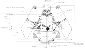
Figure 3: Spirit Rover Dimensionas
I was also able to obtain a schematic picture by contacting the same individual who made the high quality rendering pictures. Here’s is the website for more information: http://v5.nicksotiriadis.gr/mars-rover-project/
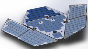
From all this information, I took measurements and a ratio of 10 was used based on the requirement that the panels needed to fit a 19-inch-wide cabinet and to the panels were scaled accordingly in SolidWorks using the scale feature.
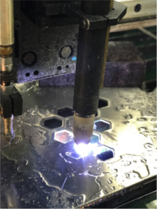
After the dimensions of the panels was established, a folding mechanism had to be devised to fulfill the cocooning state requirement. From my earlier blog post, I go over the various type of gears and types of mechanism that could perform a folding motion but utilizing worm gears for their high torque and self-locking feature was the best choice. First, torque needed to be transferred to the panels from the gears. The best option was to schedule an appointment with the mechanical design center and weld the rod to one leaf of the hinge. I tried to do this many times but failed since Electrical Engineering students do not normally get help from the mechanical center so there was no fluid was to get help. This forced the use of an epoxy called JB weld, used as a welding alternative for metals which by the end of the semester failed. In future 400D project, I hope the mechanical center will become a place where students can get their designs manufactured with ease. I have stablished some kind of relationship with Joe, the person who runs all the equipment such as welding, drilling, and plasma cutting. Here’s are my panels cut using their plasma cutter:
After making a connection from rod to panel, the gear needed to be attached firmly to the rod so that when the worm rod spins, torque is delivered to the gear, rod, and finally the panel. Ideally, metal gears need to have a press fit such as stepper motors in a printer. Press fitting gears is a science and there was no time nor the budget to get custom sized gears. So, a hollow rod was purchased from home depot and fitted in the gears bore to get a better fit from gear to rod as well as from worm rod to stepper shaft. The gears came with a set screw; this was used to secure the gears further. Since this is not the best method of connecting these gears, epoxy was used again for safe measure. For the next semester, I would recommend researching how to securely connect the gear to the shaft, rod to hinge, and worm rod to stepper shaft. Another improvement would be to make a gear box for these gears, this will serve as an encasement as well as a place to fill grease so that they are always lubed. Having lubed gears will prevent any friction between the teeth, it is crucial for metal gears.
In conclusion, another improvement would be to limit the amount of freedom the hinge has when unfolded. This can be done by welding some metal between the main panel and the right panel, this will help when the rover is being operated at the same time the panels are installed. It will remove the additional torque generated when the rover is being operated.


