Spring 2017 Preliminary Design Document: Prosthetic Hand
The Robot Company | CEO Professor Gary Hill
Project Manager: Bianca Esquivel | Mission, Systems, and Test Engineer: Chris Bautista
Electronics and Control Engineer: Forest Nutter | Design and Manufacturing Engineer: David Mendoza
Table of Contents
Program Objectives/Mission Profile
by Bianca Esquivel – Project Manager
Problem Addressing | Program Objectives Statement and Mission Profile
Project Objectives:
Fetal Amelia is an extremely rare birth defect that results in children with missing limbs. This generates a need for a product that we can provide: prosthetic limbs. Addressing the requirements of a customer that was born with part of their right arm missing just below the elbow, we have created objectives based on some of this individual’s preferred recreational activities. These objectives include creating a prosthetic hand that can unify with a prosthetic arm to allow the customer the ability to operate a computer mouse to play a game of minesweeper, pick up a cup of water to drink, and pick up a Chips Ahoy Cookie to eat.
Mission Profile:
Testing and final demonstrations for this product will be done by the customer, connecting directly onto their right prosthetic arm with screws for a sturdy connection. The hand will not draw attention to itself visually or auditorily. As far as efficiency, the prosthetic hand will be able to help the customer operate a computer mouse, pick up a cup of water to drink, and pick up a Chips Ahoy Cookie to eat. The customer will not require the help of their left hand to operate their prosthetic right hand.
Ref: Fetal Amelia
Project Requirements
by Bianca Esquivel – Project Manager
Program/Project L1 Requirements
Level 1 Requirements are considered High Level Requirements that are design independent. These requirements have been created in correspondence to the mission objective.
L1 Requirements
L1-1 Integration
The prosthetic hand shall operate with the prosthetic arm to complete 3 Tasks: Controlling a mouse to play minesweeper, picking up a cup of water, and picking up a chips ahoy cookie
L1-2 Motion
The prosthetic hand shall have individual motion in at least 2 fingers for control of the mouse (index finger and ring finger)
Ref: Finger Dexterity
L1-3 Duration
The Prosthetic Hand shall be able to operate for at least 16 minutes and 32 seconds, which is the longest duration an individual has to complete a game of minesweeper (999 seconds)
Ref: Minesweeper Info
L1-4 Mass
The prosthetic hand shall be able to lift the weight of a cup of water and a chips ahoy cookie
One chips ahoy cookie = 11 g
Weight of disposable cup = 11 g
Weight of a cup of water = 8 oz
Ref: Cup to Oz Conversion, Disposable Cup Weight, and Chips Ahoy Cookie Weight
L1-5 Independence
The prosthetic hand must be controlled by the customer without the aid of the other hand
L1-6 Cost
The total cost of the prosthetic hand project shall be no more than $350 (USD).
Ref: Cost Report Hand
L1-7 Schedule
The project shall be completed by the end of the Spring 2017 academic semester for California State University, Long Beach
Ref: CSULB 16′-17′ Academic Calendar
L1-8 Storage
The project shall fit in one of Professor Hill’s room cabinets with maximum dimensions of 71cm x 33cm x 39.5cm
L1-9 Appearance
The prosthetic hand shall be approximately the same size as the customer’s other hand (measurements from the customer taken during lab)
Index Length: 9 cm
Middle Length: 10 cm
Ring Length: 8 cm
Pinky Length: 7 cm
Thumb Length: 10 cm
Palm Length: 11 cm
L1-10 Safety
The prosthetic hand shall implement a kill switch in order to operate in adherence to the college’s safety guideline
Ref: Lab Safety
System/Subsystem L2 Requirements
Level 2 Requirements are lower level requirements that are design dependent. They must show trace-ability back to the L1 Requirements.
L2 Requirements
L2-1 Integration | System
The prosthetic hand shall operate with the prosthetic arm to complete the mission, as components of the lower-limb prosthetic system.
Subsystem:
L2-1.1 The Prosthetic Hand will connect to the prosthetic arm at the beginning of the wrist.
L2-1.2 In order for the Prosthetic Hand to work efficiently in the Prosthetic System, it will weigh less than 5 pounds to not hinder the customer.
L2-1.3 The base of the hand at the wrist will shall be circular with a diameter of 17.5 cm (measurements taken from the customer in lab)
L2-2 Power Allocation | System
The Prosthetic Hand shall be able to operate for at least 16 minutes and 32 seconds, which is the longest amount of time allowed to play a game of minesweeper (999 seconds)
Subsystem:
L2-2.1 The Prosthetic Hand shall be able to flex at least two fingers individually in order to control the left and right click of the computer mouse during the allocated minimum of 16 minutes and 32 seconds of operation time.
L2-2.2 Electronic kill switch via the arm will stop power running through the hand.
L2-3 Motors | System
The hand should flex and extend using servo motors.
Subsystem:
L2-3.1 There should be four servo motors to operate each individual finger. Two servos will operate the thumb.
L2-4 Control | System
The hand shall be able to position the fingers in operate the computer mouse, pick up the cup of water, and pick up the chips ahoy cookie.
Subsystem:
L2-4.1 The control of the prosthetic hand’s fingers and thumb flexion and extension shall be controlled using flex sensors, which are connected to the each individual toe.
L2-4.1.1 Different motions of the toes shall trigger individual movement in at least 2 fingers to control the left and right click of the computer mouse
L2-4.1.2 Grasping motion with the toes shall activate the grasping motion of the prosthetic hand
L2-4.2 When the second through fifth phalanges are engaged simultaneously, the palm should flex first, then the fingers, to help with natural gripping motion.
L2-4.2.1 There should be a millisecond delay between the fingers and the palm flexing in order to simulate natural gripping motion.
L2-5 Grip | System
The hand shall be able to grip the cup of water and the chips ahoy cookie without crushing it and without letting these items slip.
Subsystem:
L2-5.1 The hand should integrate a force sensor measuring the force being applied at the fingertips and the tip of the thumb. This will allow the hand to stop gripping so as to not crush the food items before reaching the mouth.
L2-5.2 The fingertips and thumb tip should have rubber tips, creating more friction between the fingers and the food items.
L2-6 Software | System
The hand will be coded so that each individual finger can move remotely.
Subsystem:
L2-6.1 The hand shall be controlled via an Arduino Nano, and thus will be coded using the Arduino IDE.
L2-6.1.2 The Arduino IDE should contain a bluetooth coded section so that it will connect to the flex sensors on the toes to the prosthetic fingers.
L2-7 Appearance | System
The prosthetic hand should have a humanoid design such that most integrated parts will not be visible, corresponding to the customer’s measurements: Index Length: 9 cm, Middle Length: 10 cm, Ring Length: 8 cm, Pinky Length: 7 cm, Thumb Length: 10 cm, and Palm Length: 11 cm
Subsystem:
L2-7.1 The prosthetic hand shall be designed in solidworks specifically to reflect the measurements of the customer, while using multiple prosthetic hand designs as a reference.
L2-7.2 Air dry clay should layer the mechanical design of the hand and be sanded down to look more humanoid.
Design Innovation: Creativity Exercises
by Prosthetic Hand Group
Creativity Exercises
Our group completed four creativity exercises revolving around resolving one or two primary design problems. These methods of creativity were: BrainWriting (moderated by the Project Manager: Bianca Esquivel), Lateral Thinking (moderated by the Manufacturing Engineer: David Mendoza), Attribute Listing (moderated by the MST Engineeer: Chris Bautista), and Duncker Diagram (moderated by E&C Engineer: Forest Nutter).
Link to the Prosthetic Arm: Creativity Exercises PowerPoint Presentation:
Prosthetic Hand: Creativity Exercises
The conclusive solutions of our creative exercises resulted in our team choosing to use plastic filament as the decisive material to manufacture the prosthetic hand. We also decided to implement rubber finger tips to provide a steadier grip.
System/Subsystem Design
by Christ Bautista – Mission, Systems, and Test Engineer | Forest Nutter – Electronics and Control Engineer | David Mendoza – Manufacturing Engineer
Product Breakdown Structure
by Chris Bautista – Mission, Systems, and Test Engineer
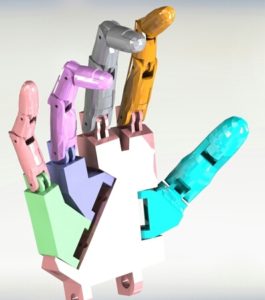
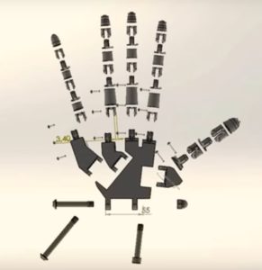
The product breakdown structure (PBS) divides the system into subsystems based on the hand location and the components in that region. We are modeling our design based off of the “InMoov” design. We will be using PLA filament to do our 3D printing. The four fingers will be designed with three part connection, one at the knuckle and the other two connections will be within the fingers. The thumb will have two part connection with and extra connection that connects it to the palm of the hand. We will be using Nylon strings to move the fingers and thumb, so that it can grip the objects. The palm will have two part connections for the palm, one part of the palm it connect to the index and middle finger and the thumb. The other part will connect the pinky and ring finger. The palm of the hand will connect to the forearm with two screws.
Electronic System Design
by Forest Nutter – Electronics and Control Engineer
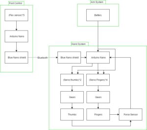
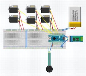
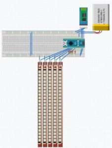
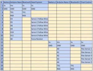
The Foot Control subsystem will use 4 Flex sensors to measure the movement in the toes. The analog signal will get sent to the arduino nano to be converted to a digital signal. The arduino will then process the data and convert it in to commands to be sent to the arduino nano in the arm through bluetooth. Then the Hand System will implement the commands by changing the PWN that is getting sent to the Servos. The Servos will then change the position of the fingers and thumb. To make sure we don’t crush the food we are including a force sensor that will feedback force data back to the arduino.
Interface Definitions
by Forest Nutter – Electronics and Control Engineer
The Interface matrix shows how the Hand system and foot control subsystem components are connected. The foot control subsystem as 4 flex sensors one for each toe and a bluetooth model to be sent to the hand. The hand system has 1 servos for the thumb and 4 dc motors for each finger, a bluetooth model, and 3 force sensor.
Mechanical Design
by David Mendoza – Design and Manufacturing Engineer
We are modeling our design based off of the “InMoov” design. We will be using PLA filament to do our 3D printing. The four fingers will be designed with three part connection, one at the knuckle and the other two connections will be within the fingers. The thumb will have two part connection with and extra connection that connects it to the palm of the hand. We will be using Nylon strings to move the fingers and thumb, so that it can grip the objects. The palm will have two part connections for the palm, one part of the palm it connect to the index and middle finger and the thumb. The other part will connect the pinky and ring finger. The palm of the hand will connect to the forearm with two screws.
Design and Unique Tasks Descriptions
by Chris Bautista – Mission, Systems, and Test Engineer and Bianca Esquivel – Project Manager
Unique Tasks
- Determine sizing of hand and wrist to be identical with correlating part (March 3, 2017)
- Create Solid Works file for simulation of grasping and positioning motion (March 24, 2017)
- Research wireless connections for flex sensor (March 3, 2017)
- Power Requirements for prosthetic hand efficiency in prosthetic system (March 10, 2017)
- Design for final PCB Board to handle Bluetooth and Arduino Nano connectivity (April 7, 2017)

