Pick and Place – Trade Off Study – Camera System
By: Kevin Ruelas (Electronics and Control)
Due to the use of a servo driver to control the existing and additional servos, a separate Arduino can be used to house an independent camera system. This Arduino will have its own code as well as utilize visual software for edge detection.
It was important to choose a camera that is lightweight, and small enough to be mountable on the current Z-Axis. The following are the cameras that I looked at that could possibly work.
| Price | Size | Weight | Resolution | Operating Voltage | |
| Miniature TTL Serial JPEG Camera with NTSC Video | 35.95 | 20mm x 28 mm | 3g | 640 x 480 | 3-5 V |
| TTL Serial JPEG Camera with NTSC Video | 39.95 | 32 mm x 32 mm | 640 x 480 | 5 V | |
| Weatherproof TTL Serial JPEG Camera with NTSC video and IR LEDs | 54.95 | 2 in x 2 in x 2.5 in | 150g | 640 x 480 | 5 V |
The Miniature TTL Serial JPEG camera fits the needs of the project the best, as it is the smallest, lightweight and still maintains a decent resolution.
The Arduino UNO by itself does not have the capability for image processing so once the picture is taken, it will need to be stored externally and then sent back to the computer to a software called Processing.
Processing is an integrated development environment (IDE) written in Java. It is here where edge detection code will be written to detect the edge of the PCB, or whatever the camera is looking at. From there the coordinates of the edge will be extracted and fed back to Gremote.
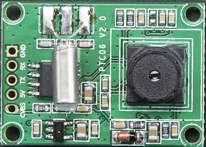
Figure 1 – Miniature TTL Serial JPEG Camera with NTSC Video
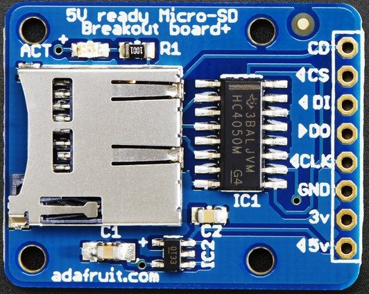
Figure 2 – SD Card Breakout board

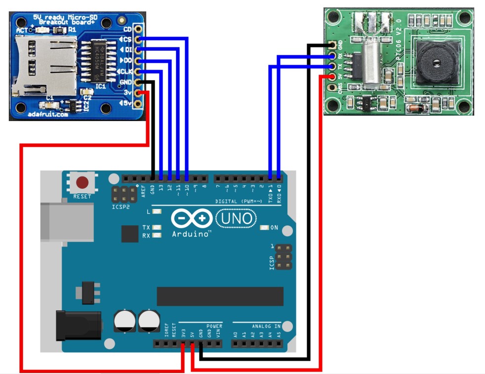
Figure 3 – Diagram
| SD CARD PINS | ARDUINO UNO PINS |
| CS (SS) | Digital Pin 10 |
| DI (MOSI) | Digital Pin 11 |
| DO (MISO) | Digital Pin 12 |
| CLK (SCK) | Digital Pin 13 |
| 3V | 3.3 V |
| GND | GND |
| CAMERA PINS | ARDUINO UNO PINS |
| 5 V | 5 V |
| GND | GND |
| TX | Digital Pin 1 |
| RX | Digital Pin 0 |
References
http://web.csulb.edu/~hill/ee400d/Project%20Folder/Camera/Camera%20Document.pdf
https://www.adafruit.com/products/1386