Thermoelectric Peltier Cooler Secondary Testing & Print Bed Installation
By W. Mevan Fernando
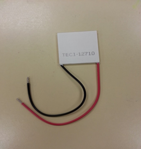
Due to the first set of TECs we purchased being faulty, we decided to purchase a single high quality TEC with a current rating of 10A. This would provide enough cooling by itself to cool the print bed.
The video below shows the print bed setup. A much larger heat sink was used along with the TEC and a fan was used to cool the heat sink. The TEC and fan were connected to our 12V, 30A power supply. Premium Ceramic Polysynthetic Thermal Compound was used on both sides of the TEC to provide better contact with the heat sink on the bottom and the aluminum print bed on top. The infrared thermometer we used before was faulty as well and hence a regular glass thermometer was used to show that the temperature of the print bed did in fact decrease. The temperature of the print bed was clearly colder than what was read on the thermometer due to the fact that all sides of the thermometer were not in contact with the aluminum. This could be seen by the condensation that was forming on the print bed and also just by touching it. Once again thermal compound was used to provide better contact with the thermometer and print bed.
Video at this link:
https://www.youtube.com/watch?v=aijkuX2GWC0
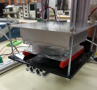
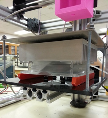
The pictures below show the installation of the whole print bed setup to our printer. 8-32 threaded rods were cut into 12” and used to attach the print bed to the printer. Two pieces of plastic were attached under the fan to ensure that there was space for airflow at the bottom of the fan.
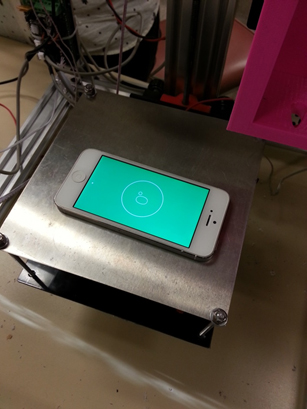
After screwing the print bed on to the printer, an iPhone app was used to check if the print bed was levelled so that there wouldn’t be any complications while printing.