E-Racer Spring 2019
IR 3DoT Sensor Shield Design
Author: Lundao Gao
Introduction
This blog post is intended for keeping a record on IR Shield Design and Manufacturing with QRE1113 for 3Dot Board in the process of E-Racer Robot Project in EE-400D Class at CSULB.
The requirements that are going to be met are:
Program Level 1 Requirements:
L1.15 Extensibility is designed into the 3DoT board by way of one 8-pin 100 mil connector located on the front of the board and two 8-pin 100 mil connectors located on the top of the board. By plugging shields into these connectors, the 3DoT board can support a diverse set of robots. All robots shall contain one or more custom-designed 3DoT shields. The 3DoT shield(s) incorporating interface electronics between the 3DoT board and sensors and/or actuators unique to the robot. Surface Mount Technology (SMT) will be employed unless a waiver for through-hole parts is granted.
Project Level 1 Functional Requirements:
L1.1 The E-Racer will drive on horizontal surfaces made of linoleum(classroom floor).
L1.3 The E-Racer shall be able to follow a course drawn on the 12’x5’ whiteboard in a classroom.
L1.4 The E-Racer shall contain a custom designed PCB for a specified purpose (i.e sensor shield).
System/Subsystem/Specifications Level 2 Requirements:
L2.4.1 The PCB shall contain the IR sensors used for line following.
L2.6.1 The E-Racer shall implement PID control to autonomously follow the line.
IR Shield Design
The software used for the design of the IR Shield was EagleCAD by AutoDesk.
The idea of the circuit design with QRE1113 from SparkFun Line Sensor Breakout – QRE1113 (Digital).
Shown in Figure 6 are the breakout board and its schematics.
![Figure 6 Sparkfun QRE1113 Digital Breakout Board: Photo and Schematics [1]](https://www.arxterra.com/wp-content/uploads/2019/04/6-1.png)
Figure 6 Sparkfun QRE1113 Digital Breakout Board: Photo and Schematics [1]
IR Shield Design Version 1
This board contains one QUE1113 IR Sensor, one 100ohm resistor, one 220ohm resistor, and one 10nF capacitor. It had been proven in IR Sensor Testing process that in order to make the robot to complete the line-following task, four sensors are needed, so the first version of schematics is basically four of above circuits connect together, which will be proven necessary and works well.
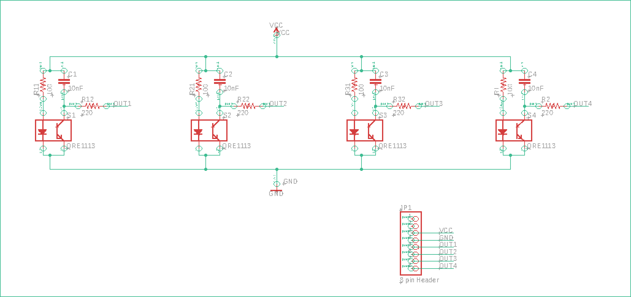
Figure 7.1 Schematics of IR Shield Design Version 1
The version 1 PCB board has arranged the components in the board view shown below:
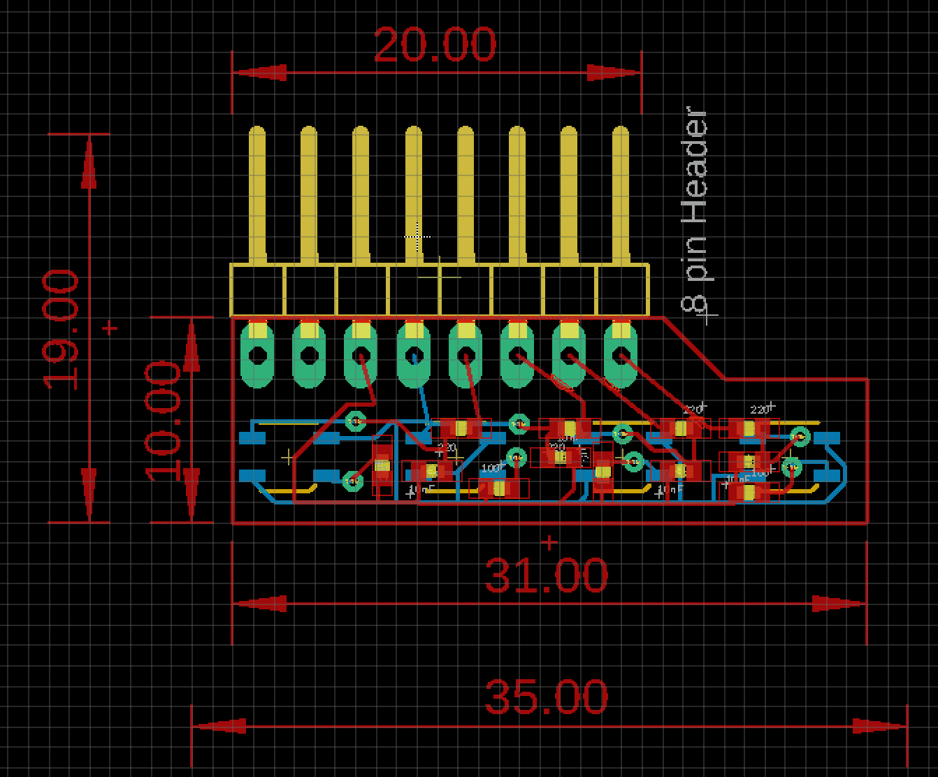
Figure 7.2 Board View of IR Shield Design Version 1
The reason there are two pins on the shield that are not connected to any components is that they will be connected to SCL and SDA header on the 3Dot board (schematics shown below in Figure 7.3), which is not needed for IR Shield design.
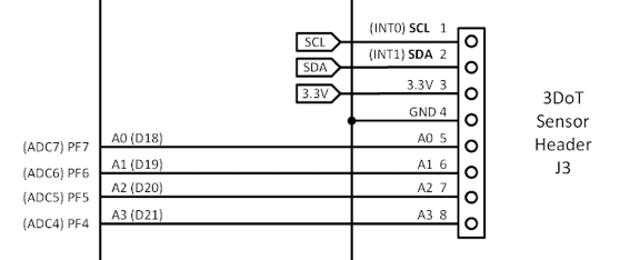
Figure 7.3
Schematics of 3Dot Sensor Header [3]
Although the basic schematic design is determined, there are minor mistakes or things that could have been done better, and also, the board design is very messy with wire traces everywhere, along with mistakes made from lack of experience and knowledge.
IR Shield Design Version 7.2 (Final Version)
After six generations, a lot of mistakes has been fixed, and many designs have been improved.
Shown in Figure 8.1 and 8.2 are the schematic and board view of the final version of IR Shield.
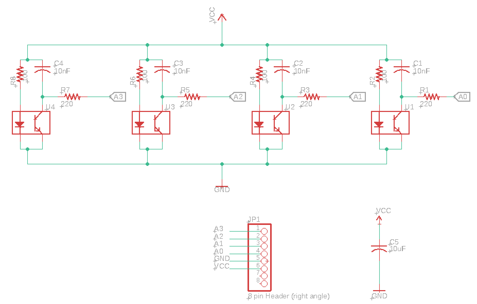
Figure 8.1 Schematics of IR Shield Design Version 7.2
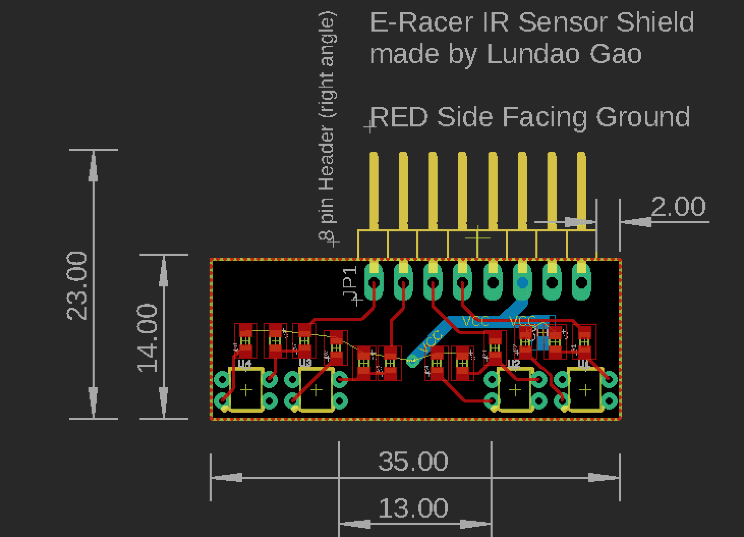
Figure 8.2 Board View of IR Shield Design Version 7.2
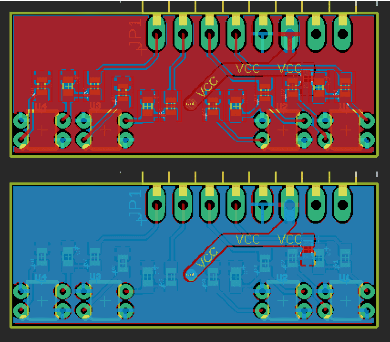
Figure 8.3 Board View of IR Shield Version 7.2, Two Layers with Polygon
Followings are the most of the modifications and arrangements I made from Version 1 and Version 7, along with reasonings.
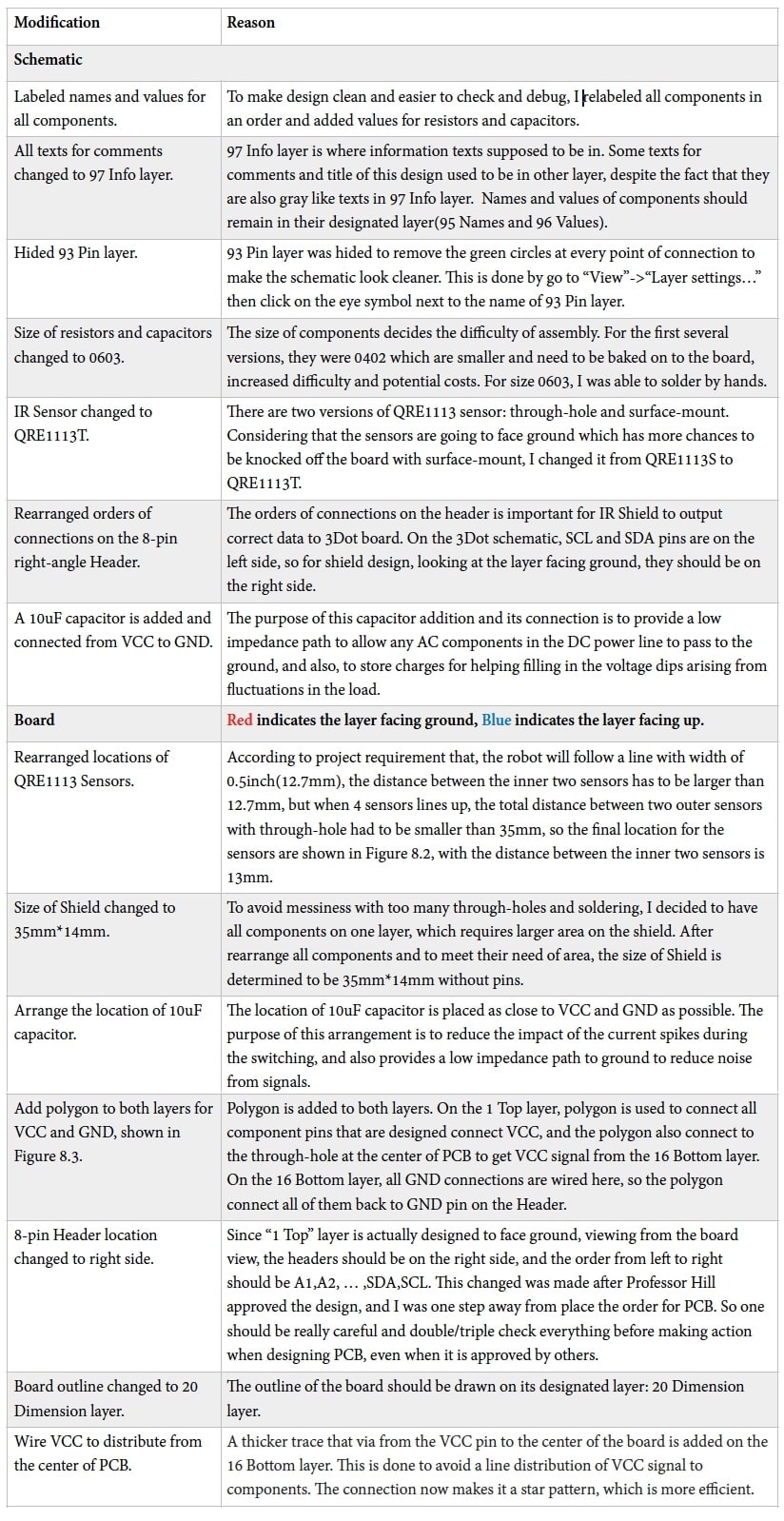
Table 1: Modifications from IR Shield V1 to V7.2 and Reasons
IR Shield Manufacturing
Gerber File Generating
Gerber file is generated by click “CAM Processor” on the top of the window-> click “Process Job” at bottom of the pop-up window after check that all necessary layers are included. For ordering PCB board later, set export file to “Export as ZIP” on the top of CAM window. These steps are usually simple for me since everything just stayed default.
Ordering PCB
PCB board is manufactured by JLC Electronics from Shenzhen, China. This company manufacture custom designed PCB at a very low price, for me, was 2 US Dollars for 5 PCBs.
I ordered through their website https://jlcpcb.com.
First, enter the basic information: the dimension(35mm x 14mm), and left default quantity(minimum 5)of PCB, default thickness(1.6mm) and default layers(2), then click “Quote Now” to go to the quote page. Figure 9 shows the quote page and all the options JLC offers for manufacturing PCB, along with selections for IR Shield for this project. The ZIP of Gerber file generated earlier should be uploaded at the top of this web page.
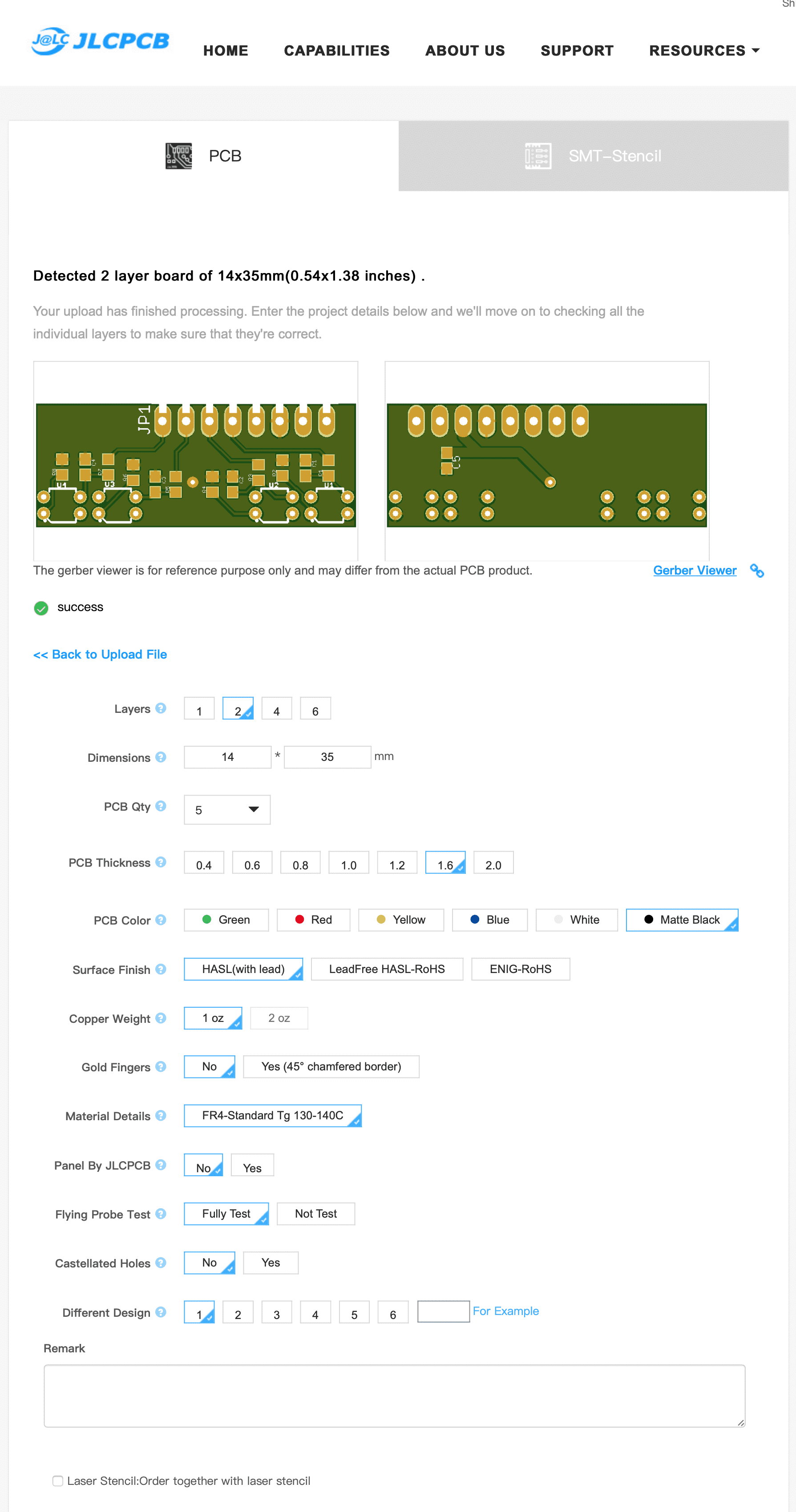
Figure 9.1 JLC Quote Web Page [4]
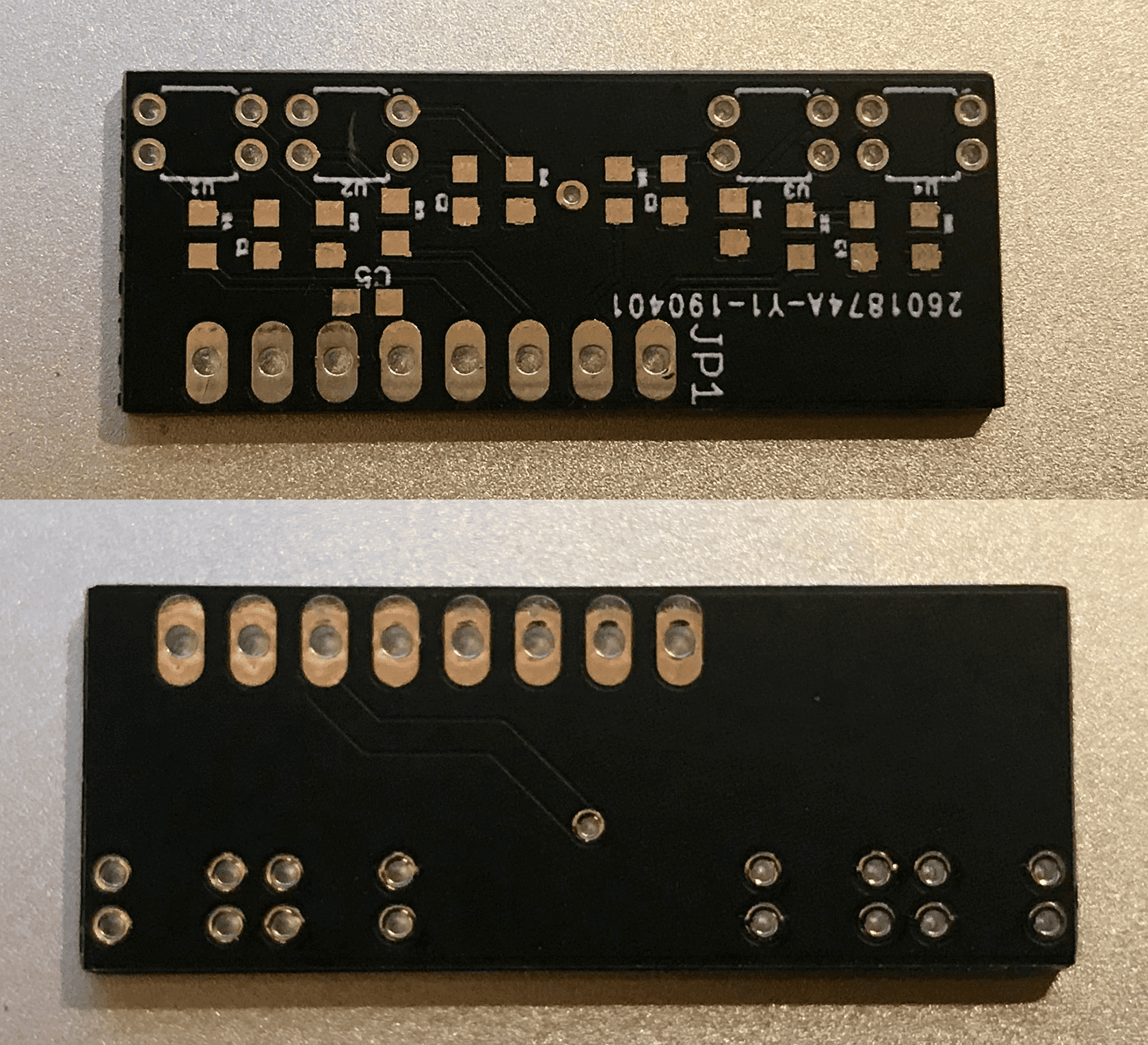
Figure 9.2 IR Shield Received from Manufacturer
IR Shield Assembly
While waiting for the board, two sets of components for the IR Shield are ordered. The reason for ordering a second set is to make sure there are backups if anything goes wrong during the assembling process.
All components are ordered from Arrow Electronics at https://www.arrow.com. When finding components, it is important to find them in the right value and physical size, which in our case, is 0603. Bill of Material (BOM) of components is made by E&C engineer which can also be automatically generated by Arrow website.
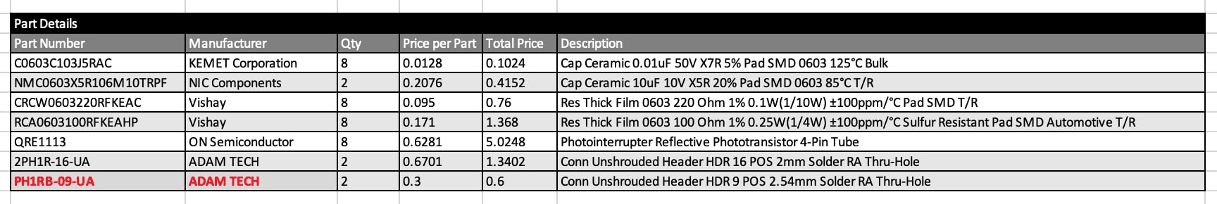
Table 2: Bill of Material (BOM) of components ordered from Arrow Electronics
A problem was found after assembling that the 8-pin header ordered (2PH1R-16-UA) had diameter of is not tight enough when plug into 3Dot to securely stay on it, then according to advice from the project manager to use another type of header shown in BOM in Table 2 in red (PH1RB-09-UA) which has thicker pins, then they are ordered and they worked well.
Assembly is done using regular soldiering iron and soldier. The final product is shown in Figure 10.
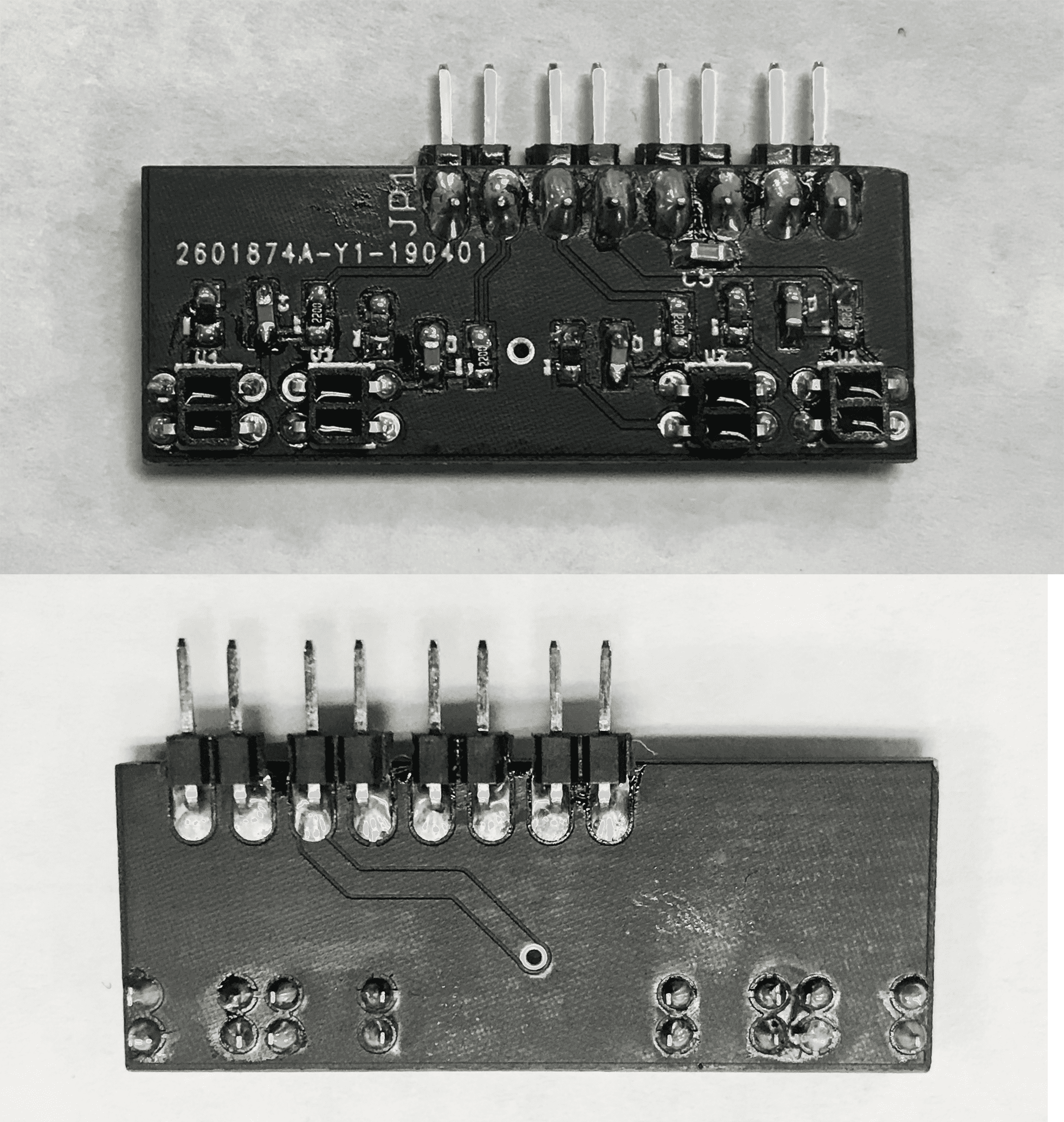
Figure 10 Completed IR Shield
Conclusion
In this blogpost, QRE1113 IR Sensor is used in PCB design.
All requirements are met during the designing process, and the finished PCB board successfully performed reflection reading tasks and worked well in line following tasks.
References/Resources
[1]”SparkFun Line Sensor Breakout – QRE1113 (Digital) – ROB-09454 – SparkFun Electronics”, Sparkfun.com, 2019. [Online]. Available: https://www.sparkfun.com/products/9454
[2]”bildr » Line Sensing. QRE1113 Reflectance Sensor + Arduino”, bildr, 2019. [Online]. Available: http://bildr.org/2011/06/qre1113-arduino/
[3]”3Dot V7.0 – Arxterra”, Arxterra.com, 2019. [Online]. Available: https://www.arxterra.com/3dotproducts/3dot-v7/?v=7516fd43adaa#tab-id-3
[4]”PCB Prototype – JLCPCB”, Jlcpcb.com, 2019. [Online]. Available: https://jlcpcb.com/quote