A System Overview of 3-D BioPrinter
By Omair Tariq, Systems and Test Engineer
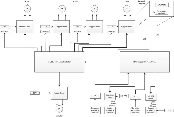
Fig. 1 System Block Diagram of the 3-D BioPrinter
Following is a system engineering perspective of the 3-D BioPrinter
1.) A 3-D Model is sent as instructions known as G-Code from the Computer to the Primary Arduino (Arduino MEGA) that are then translated by the Arduino, using the RAMPS 1.4 shield’s stepper motor drivers, into movements of the Axes Stepper motors and Extruder Linear Actuator. The instructions are sent via a USB Cable.
2.) A secondary Arduino (Arduino UNO) is used to for temperature sensing and control. The thermistors attached to the print bed and the extrusion syringe send measurements back to the Arduino, which then sends the readings back to the computer, via a USB cable, to be seen by the user. The user sets the desired temperatures of the print bed and the extruder on the computer. This set temperature is transferred via the same USB cable to the Arduino. The Arduino then translates this set temperature into Pulse Width Modulation (PWM) for the MOSFET driver and the Solid State Relay that are attached to the Print-Bed Cooler and the Extruder Heater Respectively.
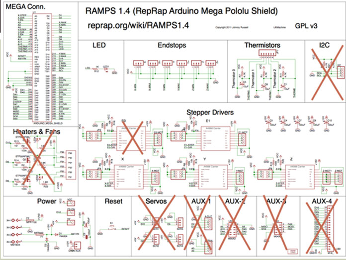
Fig 2. Detailed RAMPS 1.4 Block Diagram for 3-D BioPrinter
RAMPS 1.4 Shield
The detailed RAMPS 1.4 Block Diagram shows the sections of the shield that are being used and not being used by us this semester. Sections being utilized by us this semester:
1.) Stepper Motor Drivers
4 out of the 5 stepper motor drivers are being used to control the stepper motors and linear actuators. There are two stepper motors to control the Y-Axis, one to control the X-Axis, a linear actuator to control the Z-Axis and another linear actuator to control the Extruder. Since there are two stepper motors on the Y-Axis and only one stepper motor driver, the stepper motor drivers will be connected 180 degree out of phase.
2.) Endstops
The End Stops are switches mounted on the axes to determine the home position of each of the Axes.
3.) Reset Button and LED
The Reset Button is used to reset the Arduino whenever the need arises such as when the Arduino stops responding. The LED indicates whether the RAMPs 1.4 is on or not.
We will not be using the following sections of the RAMPS 1.4:
1.) 1 Stepper Motor Driver
2.) Heaters & Fans
3.) Sevos
4.) Aux-1
5.) Aux – 2
6.) Aux – 3
7.) Aux – 4
8.) I2C
Note: The thermistors portion of the RAMPS 1.4 is not being utilized either since we just attach a resistor to this section to fool the RAMPS shield into thinking that the thermistor is being used. This was done because the code related to the thermistors could not be commented out in the firmware. See the blogpost here for more details.
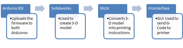
Fig 3. Softwares Used in 3-D BioPrinter
Softwares needed for 3-D BioPrinter
- Arduino IDE
- This is used to upload the MARLIN Firmware to the Primary Arduino of the BioPrinter if any modifications are made.
- Solidworks
- This is used to create a 3-D model of the desired object and generate an STL file.
- Slic3r
- This is used to convert the STL file of the 3-D model into printing instructions, known as G-Code.
- Pronterface
- Pronterface is a GUI used to interact with the 3-D printer.It is primariliy used to transfer the G-Code, generated using Slic3r , to the Primary Arduino. It can be also be used to control the movement of the X,Y and Z axis and the Extruder Linear Actuator for other purposes such as calibration.