Built-in Commands and Telemetry
Table of Contents
Built-In Commands
Internal Commands
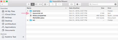
The Arxterra suite (ArxRobot App and Arxterra Control Panel) comes equipped with a set of commands that can be generally applied. The 3DoT Library, which will be used to write the 3DoT MCU firmware, is designed to process and execute these commands. A complete listing of them can be found in the keywords.txt[1] file – located inside the Robot3DoTBoard folder shown in Figure 6.6. Some useful programs for viewing the library header and source files found in this folder are Atmel Studio and Notepad++ for Windows or Sublime Text for Mac.
[1] The official list of commands is located in this Google Spreadsheet.
Figure 6.1: 3DoT Library “keywords.txt” file.
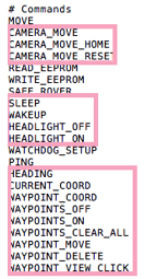
While every internal command should eventually have a corresponding handler, the 3DoT library is still under development. The internal commands without handlers are shown inside the red boxes in Figure 6.7.
Figure 6.2: Internal commands without handlers.
Built-In Telemetry
Telemetry
Now that the communication between the Control Panel to the 3DoT board has been covered (Commands), it is important to discuss telemetry – the communication from the 3DoT board to the Control Panel. Telemetry is commonly used to gather data from sensors being used by a microcontroller. While commands is the concept of the user transmitting input to the microcontroller, telemetry is the user receiving data from the microcontroller. The main difference between commands and telemetry is that commands are inputs being sent by the user manually while telemetry is data being transmitted by the microcontroller to the user automatically. For example, the sensors are constantly sending data to the control panel to update the figures and values on the control panel shown to the user. Figures 8.1 and 8.2 shown below are some examples of telemetry displayed for the user on the Control Panel. Also, telemetry is not shown through the Arxterra application on mobile devices – only on the Control Panel.
Figure 8.1: Sample “Body Temp” telemetry. Figure 8.2: Sample “Heading” direction telemetry.
Command Handler (optional)
The section of this is intended for advanced users of the Arxterra Robotics platform. If you’re controlling a simple low-cost 3DoT robot, the following material may be skipped without loss of continuity.
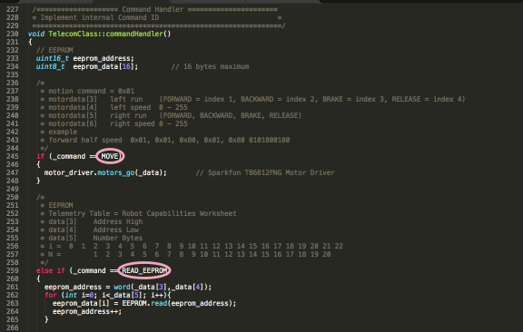
To determine if a command handler exists for the command in question, check the command handler section of the TelecomClass.cpp to verify that a handler is present for an internal command utilized in your project as shown in Figure 6.3. The TelecomClass.cpp source file can be found in the src subfolder and may be opened in Windows with Notepad++ or a C++ compatible IDE like Atmel Studio 7.
Figure 6.3: Verify if a command handler exists for a specific command, such as “MOVE”.
The Arxterra robotic platform is designed for both simple low cost 3DoT robots and large complex Mars Pathfinder class rovers. By default, the platform comes configured for low cost 3DoT robots. This section shows how you can quickly configure the Arxterra platform for Mars Pathfinder class rovers with pan/tilt camera platforms and capable of waypoint navigation. Specifically, commands related to “pan/tilt camera” and “waypoint navigation” systems can not be issued from the Arxterra suite until they have been enabled. If these commands are relevant, launch the ArxRobot app and proceed with the following steps.
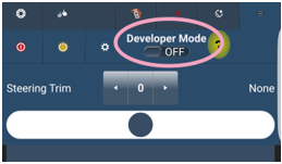
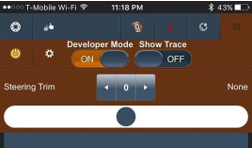
STEP 1: Press the tab in the upper right-hand corner of the application screen and toggle the switch from “Developer Mode” to the ON position.
Figure 6.4: Developer mode enable
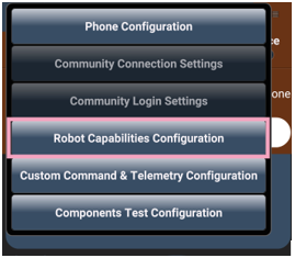
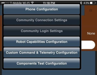
STEP 2: Press the cog wheel icon, next to the developer mode switch, and select “Robot Capabilities Configuration” from the drop-down menu.
Figure 6.5: Access to Additional Built-In Arxterra Capabilities
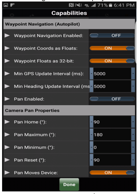
STEP 3: Configure for current project.
Figure 6.6: Waypoint and Pan/Tilt Platform Configuration Window
Waypoint Note: For the Waypoint Navigation controls to show up in the Control Panel, the ArxRobot app must be told that the MCU is capable of using this feature, by enabling it in the Capabilities Configuration view. See the following ArxRobot Testers post for a description of how it works, and our Communications spreadsheet for more details.
Built in Telemetry
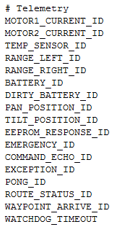
The Arxterra suite (ArxRobot App and Arxterra Control Panel) comes equipped with a set of predefined telemetry channels. The 3DoT firmware implements only one. A complete listing of telemetry channels can be found in the keywords.txt[1] file – located inside the Robot3DoTBoard folder shown in Figure 6.1. 3DoT Library “keywords.txt” file.
While every internal telemetry channel should eventually have a corresponding handler, the 3DoT library is still under development. Currently only BATTERY_ID is implemented on 3DoT robots.
[1] The official list of commands is located in this Google Spreadsheet.
Figure 8.3: Internal telemetry channels.
Battery Level Tutorial
The purpose of this tutorial is to access the status of the 3DoT board battery on the Arxterra control panel. Fortunately, all code regarding finding the battery has already been written and needs to only be “activated”. Specifically, all the code for finding and sending battery telemetry data is indeed present, but not shown in the control panel just yet. The only item shown on the control panel for telemetry is the “Phone Battery” when the phone containing the Arxterra application is initially connected as shown in Figure 8.4.
Figure 8.4: Control panel only containing telemetry for “Phone Battery”.
So why is it that even though the code has been written to send the data as a telemetry packet, it is not being shown under the telemetry section on the control panel? Keep in mind, phone battery and the Roll-Pitch-Heading figures are all examples of telemetry with the phone and not the 3DoT board. In this lab, the procedures on activating the telemetry for the 3DoT Battery will be reviewed.
Equipment:
- Mobile device with access to ArxRobot application
- Access to the Arxterra Control Panel on the computer
- 3DoT Board
Figure 8.5: Screen shown when ArxRobot application is initially opened.
STEP 1: This lab assumes the basic setup of connecting ArxRobot app with the 3DoTBoard over Bluetooth and Arxrobot with Arxterra control panel has been previously reviewed on the website. If not, start with sections “04 – Getting Started with Arxterra” and “05 – Arxterra Bluetooth and Wireless Communication”.
Begin with opening the ArxRobot application on the mobile phone. The screen should look somewhat like Figure 8-5. The main idea is the phone should be on “Remote Control” which can be set up by the orange button located at the top of this application screen.
Figure 8.6: Turn on “Developer Mode”.
STEP 2: Next, click on the button with the three horizontal bars located in the top right-hand corner of the application screen as shown in Figure 8.6. This should lead to a drop-down menu with further options. Turn on “Developer Mode”. As a result of turning this mode on makes accessing options available for the normal user.
Figure 8.7: Configurations available for the developer.
STEP 3: Access the Developer options by clicking on the gear located to the left of “Developer Mode”. In this drop-down menu, notice there are many configurations available for the developer to use as shown in Figure 8.7.
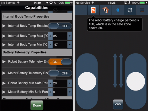
Figure 8.8: Enabling Robot Battery telemetry, and the resulting battery icon display.
STEP 4: Click on the button “Robot Capabilities Configuration”. In here, there are many available options for the user to explore and activate. For this lab, locate the options under the subcategory “Battery Telemetry Properties” shown in Figure 8.8. Lastly, enable the “Robot Battery Telemetry Enabled” option, and set the “Robot Battery Min Safe Percent” value as required. Proceed with clicking the Done button on the bottom of the application screen. The Robot Battery telemetry was successfully activated and should be displayed on the control panel.
Switch off “Remote Control” mode and switch on “Community” mode to access the control panel on the computer. Switched to Community mode, notice on the control panel, an extra gauge indicating the “Robot Battery” under the “Telemetry” section as shown in Figure 8.9.
If “Robot Battery” is still not showing, click on the gear located in the top right-hand corner of the telemetry panel. A window of telemetry options should appear with one of the options being “Robot Battery”. Turn on the “Robot Battery” option, which will allow “Robot Battery” to be displayed in the “Telemetry” section of the control panel.
Figure 8.9: Control panel containing additional “Robot Battery” gauge in “Telemetry”.
Because this lab does not necessarily require the connection of the 3DoT board, the “Robot Battery” gauge in Figure 8.9 may display 0% or 100%, depending upon the initialization routine of the current ArxRobot app version. This is due to the fact that the 3DoT was not connected with the Phone via Bluetooth and for telemetry data to be available for the Control Panel. However, if the 3DoT was connected to the phone, a real-time status of the battery of the 3DoT should be displayed as a percentage.
Post-Experiment
- If a 3DoT was not used while doing this experiment, redo this experiment when a 3DoT board is available for use. Confirm that the “Robot Battery” gauge updates on the control panel. Try draining the battery by driving a robot’s motors. Confirm if the battery is actually draining. Notice the battery level also changes while the motors are working. This is completely normal as the motors are using the power from this battery. The true battery level value is when the robot is in an idle state, where no motors are being used.
- Go back to the “Robot Capabilities Configurations” under the “Developer Options” (Step 2 and 3) and explore the different types of options available in “Robot Capabilities”. Which of these options could be useful for a specific robot? Give some thought on how to implement some of these telemetry options with a specific robot design. Keep in mind, not all these options are for only one robot design, but is for the phone, such as the internal temperature.
Telecom sendData() method
This section provides a behind the scenes look at which commands are implemented in C++ and is intended for the advanced user.
In the last section I stated that ”all code regarding finding the battery has already been written.” In this section I will trace the code starting from the Arduino “loop()” function clear to the telecom instance “sendData()” method.
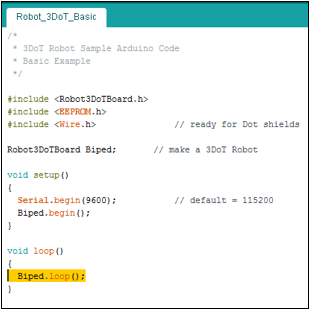
By following the “ArxRobot::loop()”, the code for finding the battery level of the 3DoT is already provided simply by creating an ArxRobot object on the main file. An example is shown in Figure 8.10.
Figure 8.10: Example of creating an ArxRobot object called Biped.
The example the tab heading in Figure 8.10 refers to the ArxRobot_Basic example located in the examples folder of the 3DoT folder. To begin, the basic example simply creates an ArxRobot object called Biped. By doing this, Biped can use any subroutines written for a 3DoT hence, the inclusion line “#include ”. Recall that telemetry is continuously updating sensory data, which means telemetry is most likely under the loop section of the main function. The loop of this main file only calls the loop of ArxRobot, so looking into the ArxRobot.cpp file, located in the src folder of the ArxRobot folder, shown in Figure 8.3 below:
Figure 8.3: ArxRobot.cpp file.
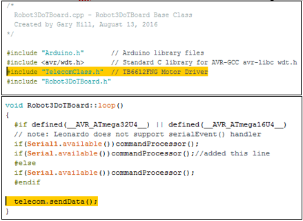
Inside the loop of this file, the file calls a subroutine from the TelecomClass file called “sendData()” as shown in Figure 8.4. Assume this is the subroutine dealing with telemetry as the rest of the code above is regarding decoding received command data. Notice again, at the top of the ArxRobot folder, there is an inclusion line for the TelecomClass.h file. So let’s again take a look into the TelecomClass.cpp file.
Figure 8.4: File calls the a subroutine called “sendData()” from the TelecomClass file.
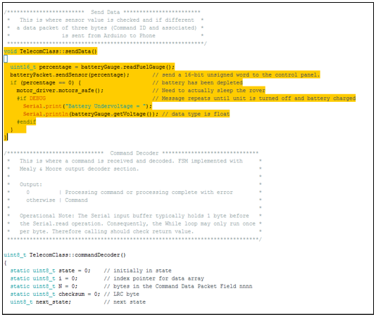
In this file, in part of the sendData method, there is code regarding reading the battery level of the 3DoT fuel gauge as a percentage. This value is later sent to another Telecom method named “sendSensor()”, which will be format the data and send it as a telemetry packet. As shown in the following lab the sendSensor() method is key to sending telemetry to the Arxterra platform.

