Assembly Robot Lab 1 – An Introduction to 3DoT & Assembly
Table of Contents
Introduction
This lab is designed to introduce you to the 3DoT Board, Microchip’s Integrated Development Environment (IDE), and AVR Assembly Language programming. Plus, you will learn about the power of library files. Library files are simply files that you instruct AVR Studio to include in your program. In this lab you are going to include two library files. One is named m32U4def and the other is robot3DoT. By the end of this lab, you will be able to make the robot execute simple movements and understand how that was done.
What Is New
The following instructions and assembly directives are used in Lab 1. If you have any questions on any instructions or assembly directives a nice source of information, in addition to your textbook, are AVR Instruction Set Manual and the Atmel AVR Assembler User Guide.
AVR Assembly Instructions
Data Transfer
in r7, PINC   // Input port C pins (0x09) into register R7
out PORTB, r7 // Output to Port B from register R7
mov r8, r7    // Move data from register r7 into register r8
Arithmetic and Logic
clr r16 // Clear Register R16
ser r17 // Set Register R17
Control Transfer
call Init3DoT   // Subroutine Call
rjmp loop       // Jump to the label named loop
AVR Studio Assembly
Directives
.INCLUDE < m32u4def.inc >      // < > means the file is in the AVR Studio folder
.INCLUDE "robot3DoT.inc"     // " " means the file is in the project folder
.ORG 0x0000                  // Code Origin
Labels
loop:       // Links the next assembly instruction or piece of data to the
               term used. (loop in this case).
Comments
;
//
/*    */     <- Used for large blocks of text. Must indicate the
                start and end with these symbols
Introduction to Programming
Before you start writing your first assembly program, it is crucial to go over the core concepts that will be influencing how the programs are written. There are several misconceptions that can severely limit a student’s programming capabilities as they attempt to memorize how the code is written or the exact structure to use. It may feel overwhelming with the amount of new material to understand and learn but these core concepts should help with that.
- Recognize that the programmer is responsible for everything.
- It is common for new programmers to think that the microcontroller is smart enough to do certain things on its own given how technology has advanced and how the example programs shown in lecture do everything without any errors. This is not true. The only thing that a microcontroller / computer / laptop will do is follow the instructions provided by the programmer. It is the programmer’s responsibility to plan out the logic of how the program will run, anticipate any issues or errors that could occur, and provide any relevant information or resources for the microcontroller to use while executing the program.
- Understand that the programmer has relative freedom within the bounds of that specific architecture.
- You may have noticed that many example programs follow a consistent structure. This is to make it easier to teach and ensure that students have a general understanding. However, this does not mean there is only one way to write the program. If you fully grasp the way things are done on a specific microcontroller, it is possible to develop the code in various ways. This depends on the microcontroller because there are differences in how they work depending on the manufacturer. It requires an understanding of how to use labels, subroutines, etc but it highlights how the programmer can be creative with how the task is accomplished. Keep that in mind when attempting to create your own programs for the labs.
- The general structure for a section of code is to (1) Load the values or variables that are needed, (2) Do / Execute the action needed, and (3) Store the results or variables accordingly. This can be applied to a complex application by breaking it down to the individual parts and handling them separately. Be aware that each part could be one instruction or multiple instructions depending on what is needed for the program.
Keeping these concepts in mind should help when creating assembly programs for a specific application. We can now move onto the more technical details of writing the code.
Introduction to AVR Studio
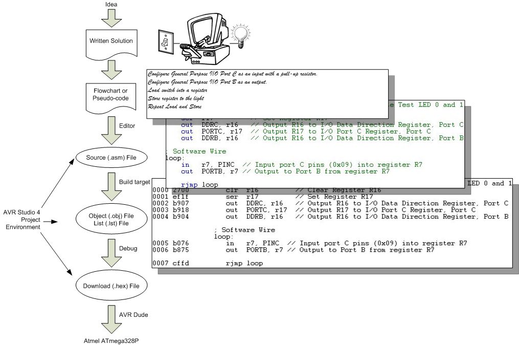
In lab, you will be spending most of your time working within an Integrated Development Environment (IDE). For our labs, we will be working in the AVR Studio IDE. As shown in the figure below and discussed in the next few sections, the IDE lets us write our program in a human readable form, known as assembly, and then translate it into a machine readable form understood by the ATmega32U4.
Create a New Project
The best way to learn about the AVR Studio IDE is to start playing with it. So let's get things started by launching AVR Studio and Opening a New Project.
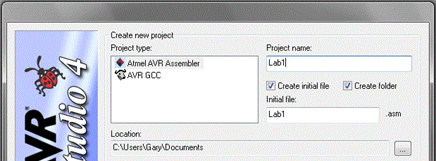
Select Atmel AVR Assembler and check both check boxes(Create initial file and Create folder). Name your project (Lab1) and browse to location where you want it saved. Click Next >>.
In the next window select AVR Simulator. For the Device, select ATmega32U4. Click the Finish button.
Congratulations, you are ready to start programming within the AVR Studio IDE!
Assembly Directives
All assembly programs contain assembly directives and assembly instructions. Assembly directives are instructions to be read by the assembler. In our lab, the assembler is included with AVR Studio IDE. As you have seen, AVR Studio is a program that runs on your computer and is responsible for translating your human readable assembly program into the machine language of the microcontroller.
We begin our program with an Assembly Directive. First, locate the program window within the IDE. This is the blank window in the center of your AVR Studio application. The title bar should include the location of your program and end with the name of your program and the ".asm" extension. Enter the following lines into the program window.
You can probably guess that here we are telling the assembler that we would simply like to include some comments for the individual reading our code. To include comments, you can use the C language notation // comment line and /* block comment */ or unique to assembly a semicolon ; character.
Now let's add some code which intended strictly for the assembler, not the reader or the microcontroller. The difference is important.
The "dots" tell the assembler that these lines are talking to the assembler and not to be turned into machine instructions.
Without overly complicating our first program, I will just note that the INCLUDE assembly directive tells the assembler to copy into our program all the text contained in a file named m32u4def.inc. For now, we do not need to know what is in this file, other than to note it will help us in writing a more human readable program.
The CSEG statement tells the AVR Studio Assembler to place the following material in the Code SEGment of memory. For the ATmega32u4, this means Flash Program Memory. The ORG statement tells the assembler to start placing code at this address in Flash Program memory.
Programming Convention Because it is so important to remember when a line is intended for the Assembler (Assembly Directive) and when a line is to be converted to a machine instruction intended for ATMega32u4 microcontroller (Assembly Instruction), I always capitalize Assembly Directives and place in lower case letters Assembly Instructions. AVR Studio is not case sensitive, so this convention is not required for your assembly program to assemble correctly - it is however required by the instructor.
Now let's add our first label. Enter the following line after the .ORG 0x0000 assembly directive:
RST_VECT:
The label RST_VECT stands for ReSeT VECTor and is only there as a point of programming style (i.e., it helps the reader know that the code to be executed on reset follows). What the assembler does is quite a different story. Whenever the assembly sees a label, it places the label name and its corresponding address, in this case we know it is 0x0000, into a look-up table.
| Label Name | Program Address |
|---|---|
| RST_VECT | 0x0000 |
Now if you ever want to reference this location in your program, you can use the name and let the assembler worry about the address.
Congratulations, you have for now completed your initial conversation with the assembler. You have asked it to include some comments, include more assembly directives located in another file, setup to write some code at address at 0x0000 in program memory, and finally to associate this address with the name RST_VECT. What you haven’t done is write anything that the AVR microcontroller will ever read. Once again it is important to know when you are talking to the assembler and when your code will be used to generate machine instructions to be run by the microcontroller. So let’s start generating assembly instructions intended for the microcontroller.
Assembly Instructions
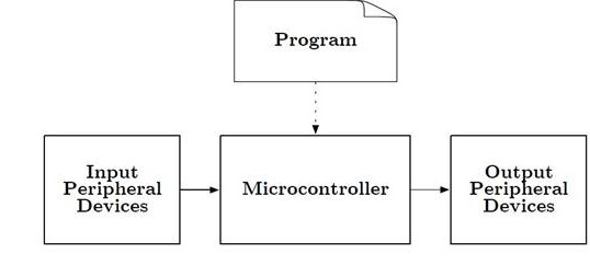
Just as you are reading the step-by-step instructions on this page so you can write your first program, the microcontroller in Figure 5 reads the step-by-step instructions contained in the program to learn what is intended by the programmer. This is the "Machine Language" of the computer. This language is comprised of only ones and zeros. For example, this binary sequence 0010011100000000 tells the AVR computer (aka microcontroller) to set all the bits in register 16 to zero. All these 0's and 1's are not very easy for us humans to understand. So instead we humans have created a human like language comprised of abbreviations (known as mnemonics). This is known as Assembly Language. By definition then, there is a one-to-one correspondence between a machine instruction and an assembly instruction. For our machine code example, the equivalent assembly instruction is clr r16.
Registers Our microcontroller contains 32 general purpose registers labeled R0 to R31. For now you can think of registers like variables which can hold up to 8-bits of information (000000002 = 010 to 111111112 = 25510). To learn more about number system read Chapter 1 "Introduction" in your textbook or Appendix A - Number Systems in my Lecture 1 notes.
It is finally time to write our first assembly instruction. Add the following assembly instructions to your program.
rjmp reset // jump over the IVT, tables and include file(s)
The assembly instruction rjmp reset instructs the microcontroller to jump to the yet to be defined label named "reset". You will also see I have included a comment. The meaning of this comment will become more clear over the remainder of the semester.
The Anatomy of an Assembly Instruction
Each assembly instruction is defined by an operator and one or two operand fields. For our clr r16 example, the clear instruction's operator is clr and it has one operand r16. Our first program line also contains a single operand instruction. In this case, the operator is rjmp and the operand is reset.
3DoT Board Schematic & Block Diagram
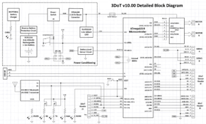
The end goal of these labs is to program a robot utilizing the 3DoT board and be able to navigate a maze autonomously. Shown below are the major features of the 3DoT board and the block diagram of the latest version.
3DoT is a micro-footprint 3.5 x 7 cm all-in-one Arduino compatible microcontroller board designed for robot projects.
- ATmega32U4 Microcontroller Unit (MCU)
- Power from a single CR123A 650mAh rechargeable Li-ion battery
- Integrated 3.7v Li-ion battery charger
- All digital logic powered from Low Dropout (LDO) 3.3v regulator with power and ground output header pins provided.
- Battery Level Sensor
- DRV8848 Dual DC Motor Driver
- 5.0v Turbo Boost for driving DC and servo motors
- Reverse voltage and overvoltage protection circuitry
- Android and Apple iOS application software (HM‑11 Bluetooth BLE module required)
- 2x8 pin Arduino-like shield connectors
- One 8-pin forward-facing sensor shield connector
- Two 100 mil standard Servo connectors
It would be ideal to spend some time analyzing the block diagram to get a better understanding of the capabilities of the 3DoT board but we will focus on the connections between the motor driver and IR sensors for Lab 1.
The main objective of Lab 1 is to understand the different components of the EE 346 robot and start to develop some basic control schemes. We will focus on understanding how the robot takes in sensor readings and can use them to drive the motors in a specific way. The end goal of all of the labs is to be able to program the robot to automatically navigate your path from prelab 1.
The Robot3DoT.inc Include File
To simplify your life - it is after all the first lab - I have already written all the assembly code you need to work with the two DC motors included with your CSULB 3DoT board. This code is contained in a separate file named robot3DoT.inc. We will add this file to our program in the same way we included the m32U4def.inc "include" document in an earlier part of the lab. Let’s begin.
- Download the file from BeachBoard. Make sure to place it within your Lab1 project folder or else you will get some errors when compiling.
- Unlike, the m32u4def.inc file which contains equate assembly directives, the robot3DoT.inc file includes subroutines which need to be run by the microcontroller.
- Add the following lines of code to your Lab1 project file.
.ORG  0x0100  // Bypass IVT
.INCLUDE "robot3DoT.inc"
reset:
Quick Review and New Directives to the Assembler
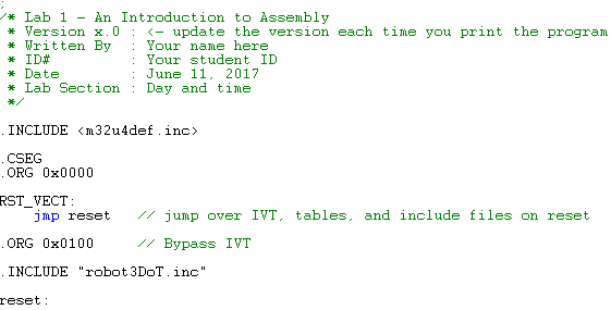
Here is what your program should look like now.
- Can you identify the comments?
- Can you tell which lines contain Assembly Directives and which contain Assembly Instructions? Remember assembly directives typically, but not always start with a period and use upper case letters; while assembly instructions use lower case letters.
Do you remember the first INCLUDE assembly directive from earlier in the lab? The m32u4def.inc library is written by Atmel and allows you to use names in place of numbers. In the following example the mnemonic PINC is “equated” to the number 0x06 in the library. If you like, you can open the m32u4def.inc file in AVR Studio and using the find tool, locate this directive.
.EQU PINC = 0x06
Up to this point our program has only contained comments, assembly directives, and labels. The first actual instruction is the previously discussed rjmp reset. So when you press the reset button, the AVR processor will first run the rjmp reset instruction. The rjmp instruction tells the processor to jump to the code starting at the reset label. This means the program will jump over (bypass) a table known as the IVT (to be covered later in the semester) and all the code included in m32u4def.inc. Which is a good thing; because we do not want to run any of the included programs until we are ready.
I wrote the robot3DoT.inc library. This library includes subroutines like Init3DoT, and ConnectToMotors which allow you to work with the 3DoT board without knowing the details of how it works.
Why are the two include files placed at different locations in the program?
The m32U4def.inc library is written by Atmel and allows us to use mnemonics (abbreviations like PINC) in place of numbers (like hexadecimal 6). To allow us to use these mnemonic names as quickly as possible we insert this library at the beginning of the program. The Init3DoT library is written by the instructor and contains instructions. This code must not be executed at reset so the library is inserted after the first jump instruction (rjmp reset) and above the label reset.
If you have played around with the Arduino IDE, you know that all Arduino programs have an initialization section named setup() and a looping section named loop(). Our assembly program written within the AVR Studio IDE will be configured in a similar fashion. In our case, the initialization section is labeled reset: and the looping section is again named loop:. In the next section you will write the initialization section to be used throughout the semester.
Initialization Section
How to Initialize the Stack
To accomplish almost anything useful in assembly you write a subroutine. To allow us to work with the 3DoT board I have written a number of ready-made subroutines for you to use. When you call a subroutine you need to save your current location on a stack. All computers have built-in hardware stack support. However, before we can save our return address on the stack we need to initialize our stack pointer (SP) register. You will learn more about stacks as the semester progresses. Add the following lines of code to your program right after the reset label.
reset:
  ldi r16, HIGH(RAMEND)
  out SPH, r16
  ldi r16, LOW(RAMEND)
  out SPL, r16
How to Use the Init3DoT Subroutine
We are now ready to call our first subroutine. Add the following line to your program.
call Init3DoT // Initialize 3DoT board with both motors OFF
The Init3DoT subroutine takes care of all the initialization required to use the 3DoT board. This includes defining the various input and output pins for the major subsystems, preparing the motors, and putting the robot into a waiting state before the user commands it to do something. You only need to call it once at the beginning of your program, just after stack initialization. That is it, you are now ready to work with the 3DoT board - allowing you to read IR sensors, run the motors, and more. We will go over this initialization process in more detail throughout the semester.
Understanding How The Infrared Sensors Work
As we start working with the robot, it is crucial to understand how it receive inputs and utilizes them to determine the appropriate output such as moving forward or turning. The 3DoT Robot has four infrared sensors located on the IR shield that are used to detect information about its surroundings. If you are not familiar with this type of sensor, it will be covered in more detail in lab 3. For now, the core concepts to remember are that the IR sensors are used as inputs to determine what is below the robot, different values are returned based on the material or color of the surface the robot is on top of, and the program that you write will determine what to do with that information.
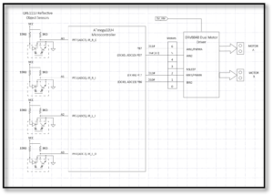
With this in mind, we will be performing an exercise to show how the IR sensors can be linked to both motors by creating "software wires" with our code. What this means is that depending on the value returned by the IR sensor, something could occur such as the motors turning or stopping. You may print out a page with a couple of black lines spaced apart by about a quarter inch to experiment with what the sensors will read. A simpler way is to use your fingers to cover the sensors entirely. Covering the sensors will imitate the robot being on white paper, so keep that in mind. We will be using different combinations to see their effects if each sensor was connected to one of the four motor driver pins shown in the diagram below. Refer to the following table and diagram to understand what each sensor is controlling and what the different combinations should do. Keep in mind that the black lines will be detected as values of 1 and the white space will be values of 0. Of the 16 possible combinations, all repetitions and unnecessary results are omitted.
| PF7 | PF6 | PF5 | PF4 | Expected Result |
| 0 | 0 | 0 | 0 | No movement. |
| 0 | 0 | 0 | 1 | Motor A is moving while Motor B is stopped |
| 1 | 0 | 0 | 1 | Both motors are moving. |
| 1 | 0 | 0 | 0 | Motor A is stopped while Motor B is moving. |
| 1 | 1 | 1 | 1 | Both motors are stopped. |
At this point, we are ready to write the code for our main program. This is indicated with a new label called loop. The purpose of this section is to have the code that will be continuously executed, which is separate from the initialization section that was focused on the setup of everything. Please add the following lines of code after the call Init3DoT instruction as shown.
....Previous Code....
    call Init3DoT          // Initialize 3DoT Board with both motors off

loop:                      // Start of main program
    in R24, PINF           // Take in inputs from IR sensors
    rcall TestMotors       // Run subroutine that will connect sensor values to motor driver pins
    rjmp loop              // Go back to the beginning of this section (repeat main program)
Let's analyze what each instruction does.
- The instruction in R24, PINF will take the values from the I/O register PINF and copy them to general purpose register 24. This effectively brings in the values from the IR sensors for the microcontroller to work with. The reason the I/O register PINF is used comes from the fact that the IR sensors are connected to PF7 - 4, which are part of the Port F pins.
- The rcall TestMotors instruction will take the final values in register 24 and copy them to the motor driver pins. You will notice that the four pins are all located on different ports such as B, C, and D. Rather than overwhelm you with multiple lines of code, the TestMotors subroutine has been provided to handle this for you. The rcall instruction functions just like the call instruction where it will execute a subroutine that has been defined or provided from an include file.
- Finally, the rjmp loop instruction will cause it to go back to the beginning of the loop section and repeat the code continuously.
Assemble and upload the code to the robot. Test all of the combinations and make sure you understand what is occurring. After this, we are ready to move onto the next step of using the IR sensors to control both motors to move in a straight line.
Controlling the Motors
Given the quick introduction during the exercise with the IR sensors, it is a good time to go into more detail about the input and output ports. The General Purpose Input and Output (GPIO) ports of a microcontroller (MCU) allow you to read pins and write to the pins of the MCU. To read a pin means – to record if the voltage on the pin corresponds to a logic 0 (Low) or logic 1 (High). To write to a pin means – output a voltage to the pin corresponding to a logic 0 (Low) or logic 1 (High). Figure 6 is a close-up picture of the interface between the ATmega and it GPIO ports and the DVR8848 Motor Driver. The mnemonics inside the ATmega32U4 correspond to the GPIO port bits. The numbers outside the box correspond to the Arduino naming convention. We will be working directly with the GPIO ports. Instead of mapping it to just one motor, we will not be configuring it as shown in figure 6.
Figure 7 is the truth table for the DVR8848 Motor Driver taken from the datasheet. As a practicing engineer, much of your time will be spent reading datasheets and translating that information into a schematic and software.
Ultimately, we want to know what settings make our robot go forward, backward, turn right, and turn left. Because of how the motors sit inside the robot, one of the motors will be going in the opposite direction of the other. Keeping in mind that the USB connector and switch are the back of the robot, the left motor must be plugged into slot A and the right motor is plugged into slot B. With that convention, the robot will move forward if the right motor goes clockwise and the left motor is counter clockwise. If you followed the video for assembling the 3DoT robot, it will simplify to 0b01 for going forwards and 0b10 for going in reverse. If that is not the case, please discuss the issue with your lab instructor before moving forward.
| AIN1 | AIN2 | BIN1 | BIN2 | Effect |
| 0 | 1 | 0 | 1 | Robot moves forward |
| 1 | 0 | 1 | 0 | Robot moves backwards |
Feel free to test the other combinations to get the robot to spin left, right, or around given the table below. The reason we chose to spin the robot instead of turning is to keep the movement consistent.
| Action | Input | |||
| Left motor | Right Motor | |||
| AIN1 | AIN2 | BIN1 | BIN2 | |
| Motor Off | 0 | 0 | 0 | 0 |
| Forward | 0 | 1 | 0 | 1 |
| Spin Left | 1 | 0 | 0 | 1 |
| Spin Right | 0 | 1 | 1 | 0 |
| Reverse | 1 | 0 | 1 | 0 |
As you may have noticed, we do not need to connect all four IR sensors to the motor pins directly. If we do, there will be major issues with getting the motors to move the way we want to within the maze. For this reason, we will only be using the two outer IR sensors for the rest of the semester. They will be used to detect the walls if the robot starts to deviate from moving in a straight line, which is more common than you might think. This is because of various factors such as the motors not outputting the same number of rotations when operating at the same voltage, differences in friction for the gear train, and the battery draining over time as it is being used. They all interfere with the assumption that it would be easy to get our robot to keep moving forward in a straight line.
For all future labs, this will be how the information for controlling the motors will be formatted. Using register 24 as an arbitrary register to hold the information, it will look like the following:
| R24 | Bit 7 | Bit 6 | Bit 5 | Bit 4 | Bit 3 | Bit 2 | Bit 1 | Bit 0 |
| X | X | X | X | AIN1 | AIN2 | BIN1 | BIN2 |
The X indicates that we do not care what their value is because it is not being utilized for anything. By default, you can set that to 0 to make it easier to manage. At this point, you should notice that only one of the bits from each pair will need to be a 1 in order to get the robot to move. At this point, we want to directly control the motors and ignore the IR sensors. It is possible to link the IR sensor to the motor driver pin but that implementation leads to more problems than it resolves. We will be handling the IR sensors in a slightly different way in future labs. We will want to directly control which direction the motors are going, so you will want to get used to this format and using the WriteToMotors subroutine.
....Previous Code....
call Init3DoT // Initialize 3DoT Board with both motors off

loop: // Start of main program
    ldi R24, 0x05 // Test combination to get robot to move forward (01) for both motors
    rcall WriteToMotors // Run subroutine that configures motors based on input given
    rjmp loop // Go back to the beginning of this section (repeat main program)
It may seem like a very minor change but the most important idea to take away from this is that it is crucial to understand what each subroutine you are using will do. You may take a look at the robot3DoT.inc file to see all of the code involved.
Directly Controlling Both Motors
Now, you may be wondering how we will be controlling the robot to perform turns while navigating the maze. The ConnectToMotors subroutine is only meant to make the robot move forward based on what the IR sensors are detecting (should be white paper). In order to properly control the robot, we will be using another subroutine called WriteToMotors in future labs. This will use a value that has been formatted properly to get the motors in a specific way. For example, if you want the robot to start spinning to the left, the value that needs to be set in a register is 0b00001001. This will be combined with another subroutine that will adjust the speed of the motors to accurately control how the robot traverses the maze.
With that, we are now done with Lab 1. The rest of the time will be spent exploring the simulator / debugger within AVR Studio 4 and understanding what was accomplished. For those of you that are interested in going further, please take a look at the design challenge described below.
Design Challenge – Wall Following Algorithm (5 points)
You can skip this section if you are happy receiving a passing or even a good grade on the lab. If you want to receive an excellent grade you will need to accept the challenge. Specifically, the maximum grade you can receive on the prelab 1 plus lab 1 if you do not accept the challenge is 25 points out of 30 (83%).
To accomplish this challenge you will need to learn a few new instructions: com, bst, and bld. A nice source of information on assembly instructions is the AVR Instruction Set Manual.
The objective of the design challenge is to teach your robot how to follow the walls and adjust appropriately to stay within the maze boundaries. This requires a different solution to what has been covered in the lab so far. Instead of using the sensors to control a single motor or loading a value to be used with the WriteToMotors subroutine, we will be using the two outer IR sensors to detect when the robot strays from the path. You should be using the maze from the kit that you ordered. If it has not arrived yet, you may print out a test setup with two black lines that are spaced apart about 2.5 inches. For this scenario, the robot will need to keep moving forward as long as it detects white and adjust the motors in a way that it will correct itself if a wall is encountered on either sensor. In order to make sure that we consider all possible situations and what needs to be done, fill out the following table.
| Input | Condition | Action | Output to Motor | ||
| IR_L | IR_R | Motor A | Motor B | ||
| PF5 | PF6 | Bit #? | Bit #? | ||
| 0 | 0 | Walking down the path | forward | ||
| 0 | 1 | Right sensor over the path | veer right | ||
| 1 | 0 | Left sensor over the path | veer left | ||
| 1 | 1 | Next Room / Wall | stop | ||
If you understand the table correctly, you should discover that all you need to do to implement the truth table is wire the complement of the input with its corresponding motor driver bit. Keep in mind that we want the robot to keep moving forward, so choose the appropriate bit to work with.
Now all we need to do is wire the complement of each object IR sensor input to its corresponding motor output. As a load-store architecture, we will need to input our sensor inputs into a register, wire them up, and then output to the motors. Using any of the provided subroutines will interfere with what we are trying to do, so refer back to figure 6 for an idea of how the data needs to be handled.
Test your code and if everything is working correctly, your robot should adjust itself when it hits either of the vertical walls on the maze. For the lab assignment submission, please indicate on the title page that you are attempting the design challenge. Insert the design challenge code where it is appropriate in the base lab. You do not need to create a separate project just for the design challenge.
Uploading the Code
At this point, you are ready to test the code with the robot. To do this, there are a few things that need to be prepared.
- Make sure to have assembled the program and that the hex file that is created is the latest version.
- Connect the 3DoT board to your computer and take note of which COM port it is using while in PROGRAM mode. You can find that information by running the device manager and expanding the Ports and COMs category.
- Create a batch file with the following command.
-
- You can make a batch file by opening Notepad and pasting the command below.
- When saving the file, make sure to change the file type from Text document to All Files under the Save As Type option.
- Erase everything in the file name area and make sure that it is exactly upload.bat
-
avrdude -v -p atmega32u4 -c avr109 -P \\.\COM9 -b 57600 -D -U flash:w:Lab1Test.hex
pause
Keep in mind that you will need to make adjustments to the command based on the file name and COM port being used. In this example, the file name is Lab1Test and the COM port used is 9. You can make copies of the batch file and edit it by right clicking and selecting the edit option.
Once that is all prepared, make sure the upload.bat file is in the same folder as the hex file for the lab you want to upload. In this case, it should be in the Lab 1 folder. With the 3DoT board connected and set to PROGRAM mode, run the upload.bat file. If everything goes well, it should successfully upload and start executing when the board is put into RUN mode.
Lab 1 Deliverable(s)
|
All labs should represent your own work - DO NOT COPY. Submit your list file as defined below. Make sure that the code compiles without any errors. Do not forget to comment your code. Lab 1 Demonstration
|
How to Create and Print-out a List (.lst) File
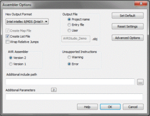
At the end of each lab, you will turn in a List file version of your program. A list file contains both your assembly program and the machine program generated by the assembler. First let’s verify that AVR Studio is set to generate a List file. In the menu bar select Project and then Assembler Options
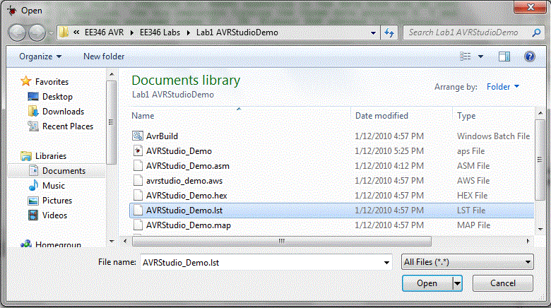
Now whenever you assemble your program, a file with a .lst extension will be created in your project folder. Assemble your program and then open the generated list file.
You will see that along with your program the list file includes a lot of other stuff. Most of this is the text from the included m328pdef.inc document. This is the document that includes all the equate Assemble Directives which allow us to use mnemonics for all our registers in place of their actual addresses. If you have not done so already browse this material to see how AVR Studio does it. You should see something like the following.
AVRASM ver. 2.2.7 c:usersDocumentsLab1Lab1.asm Tue Aug 21 13:05:53 2019

[builtin](2): Including file 'C:/Program Files (x86)AtmelStudio7.0PacksatmelATmega_DFP1.2.209avrasmincm328pdef.inc'
c:usersDocumentsLab1Lab1.asm(10): Including file 'C:/Program Files (x86)AtmelStudio7.0PacksatmelATmega_DFP1.2.209avrasmincm328pdef.inc'
c:usersDocumentsLab1Lab1.asm(16): Including file 'c:usersDocumentsLab1spi_shield.inc'

/* Lab 1 - An Introduction to Assembly

* Version x.0 <- update the version each time to print your program
* Written By : Your name here
* ID # : Your CSULB student ID number
* Date : Date the lab report was turned in, NOT THE DATE DUE
* Lab Section : Your day and time
*/

;***** Created: 2011-02-19 12:03 ******* Source: ATmega328P.xml **********
;*************************************************************************
;* A P P L I C A T I O N N O T E F O R T H E A V R F A M I L Y
;*
;* Number : AVR000
;* File Name : "m32U4def.inc"
;* Title : Register/Bit Definitions for the ATmega32U4
;* Date : 2011-02-19
There is a lot of extra material that is not useful, so there are several things to remove. Everything that comes from any include file must be removed since it is not a part of the main code. Delete material from this line...
;***** Created: 2019-12-11 15:36 ******* Source: ATmega32U4.xml **********
;*************************************************************************

up to and including this line.

; ***** END OF FILE ******************************************************
Your list file must include the AVR Studio Assembler version and time stamp!
AVRASM ver. 2.1.42 Tue Aug 23 16:57:15 2019
The "Resource Use Information" should also be deleted before you print out your list file.
Delete material from this line...
RESOURCE USE INFORMATION
------------------------
up to, but not including this line.
Assembly complete, 0 errors, 0 warnings
You can clean up and format the final version of your file in AVR Studio or your favorite text editor. Regardless of the text editor your final document should be formatted as follows.
Font: Courier or Courier New
Size: 9 or 10 point
Paragraph Spacing: 0 pt before and after
Line Spacing: Single
Page Layout: Landscape
Next, clean up unwanted spaces so your code is aligned and easy to read. DO NOT FORGET THIS STEP. Your touched up list file should now look something like this template.
AVRASM ver. 2.1.42                              Tue Jan 10 11:24:47 2019

/* Lab 1 - An Introduction to Assembly
 * Version x.0 <- update the version each time to print your program
 * Written By  : Your name here
 * ID #        : Your CSULB student ID number
 * Date        : Date the lab report was turned in, NOT THE DATE DUE
 * Lab Section : Your day and time
 */

.CSEG
.INCLUDE
.ORG 0x0000
RST_VECT:
00000 c131          rjmp reset               // jump over IVT, tables, and include files
.ORG 0x0100              // place all the code that follows starting at the address 0x0100.
.INCLUDE "robot3DoT.inc"
reset:
// Initialize the stack pointer
000132 e008        ldi r16, HIGH(RAMEND)   // IO[0x3e] = 0x08
000133 bf0e        out SPH, r16
000134 ef0f        ldi r16, LOW(RAMEND)    // IO[0x3d] = 0xFF
000135 bf0d        out SPL, r16
000136 940e 0100   call Init3DoT       // Initialize 3DoT Board with both motors off.

                   loop:
                        //in r16, PINF
                        //cbr r16, 0x0F
                        //out PORTD, r16

0001c0 e20c             ldi r16, 0x2C
0001c1 2f80             mov r24, r16
0001c2 940e 016f        call ConnectToMotors
0001c4 cffb             rjmp loop
Assembly complete, 0 errors, 0 warnings
NOTE: THIS IS JUST AN EXAMPLE. YOUR LIST FILE SHOULD CONTAIN THE CODE FOR THE LAB YOU ARE SUBMITTING.
Finally, if you have not done so already, set your printer page layout to landscape mode. Preview your printout before you actually print it out to save paper. Double check your document to make sure there is no word wrap. Your printout should never include word-wrap. If you do see a line wrapping in the print-out, go back and correct the line and re-print your list file.
Lab 1 Deliverable(s) / Checklist
STOP Read the Lab READ ME document contained in the Labs Folder. Be absolutely sure you have followed all instruction in the "Lab Formatting” section of this document. Points will be deducted if you do not follow these instructions. You have been warned.
If you have not done so already, please purchase a Lab Notebook. Follow the guidelines provided in the “Lab Notebook” section of the Lab READ ME document.
Make sure you have read and understand the “Plagiarism” section of the Lab READ ME document.
All labs should represent your own work - DO NOT COPY.
Remember before you turn in your lab...
- Did you convert your code for the exercise with controlling a single motor into comments?
- Your lab report includes a title page with your picture (one that will allow me to match a name with a face), lab number, your name, today’s date, and the day your lab meets
- The above information is duplicated in the title block of your assembly program as described in the lab. Do not forget to include the first line of your program containing the title of the lab. If you are not careful this line may be deleted and points deducted.
- Your list file should include the AVR Studio Assembler version and time stamp.
- Your list file should not include material from the m328pdef.inc or spi_shield libraries or Resource Use Information.
- Include the Assembly line indicating that your Assembly program contains no errors or warning in syntax.
- Your list file should be formatted as defined here.
Font: Courier or Courier New
Size: 9 to 10.5 point
Paragraph Spacing: 0 pt before and after
Line Spacing: Single - All fields within the program area (address, machine instruction, label, operand, destination operand, source operand, comment) must be aligned.
- Your list file printout should be in landscape and not have any lines wrap from one line to the next.
- Never turn in a program that is not debugged (i.e., contains logical errors).

