Assembly Robot Prelab 2 – Understanding the Robot’s motion
Table of Contents
Introduction
The focus of this prelab is to help you understand how the robot will be navigating through the physical maze, provide details on the new subroutines that will be used in Lab 2, and cover some of the general rules about subroutines. While you may have felt overwhelmed with all of the information provided in Lab 1, all subsequent labs and prelabs will be focused on one or two key topics that should be more manageable. For example, instead of worrying about how to program the robot to maneuver the path defined from prelab 1 right away, we will break it down into the basic, repeatable actions and combine those together.
Details about the Physical Maze
At this point, you should be fairly familiar with the printed maze that is part of the kit for the labs. The finer details about its design were omitted to keep things simple at the beginning of the semester. By the end of the semester, you will be expected to demonstrate the robot going through the maze in two different ways. The first way is to have it go through the physical maze and the second way is to show the program going through the virtual maze in the simulator.
The physical maze is made up of the artwork for the the walls (hedges) in the maze and the grid of intersecting lines to show the boundaries of each room. Figure 1 provides a closer look at some of the possible room configurations the robot will encounter. The walls of the room are in a different color (green in this case) and it is surrounded by a black outline in order to help the robot navigate properly.
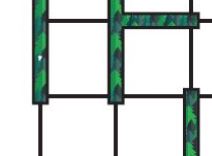
Figure 1: Segment of maze
In order to keep things simple and cost effective, the robot will be using a wall detecting algorithm to navigate through a 2D maze that is printed on paper. The algorithm will keep the robot moving in a straight line as it transitions to the next room and make sure that it moves away from a wall if it deviates to the left or right. This design was finalized after several different methods were considered such as using ultrasonic sensors to detect the nearby surroundings. The following questions are meant to help emphasize that different types of programs could be developed to solve the same problem.
Question 1 – What are some of the issues that will need to be resolved if the robot is using a wall detecting solution? Consider what else the robot will encounter as it navigates the maze.
Question 2 – How many ultrasonic sensors would be required if the maze was 3D instead of 2D (physical walls made instead of printed on paper)? Provide your reasoning for that amount.
Question 3 – Should the ultrasonic sensors be continuously on while the robot is moving through a 3D maze? Why?
Subroutine Basics
So far, the term subroutine is probably still pretty vague. In Lab 1, Init3DoT and WriteToMotors were introduced with a brief description of what they did. You were told to simply use the call instruction with them and move on. As we continue through the semester, you will be creating your own subroutines and understand how to utilize them properly.
The term subroutine refers to a programming methodology that can help improve the structure and efficiency of your code. There are several rules to follow to ensure that things will work properly. We will cover those in later labs. The main focus for now is recognizing what they are used for and how we define the names. Subroutines are a group of instructions that achieve a specific result and has been given a unique name/label by the programmer. For example, the Init3DoT subroutine is composed of several lines of code that configure all of the input and output pins for the IR sensors and motor driver. Subroutines could be called once (as with Init3DoT) or multiple times (as with WriteToMotors if testing many configurations) depending on what the programmer is trying to do. All of these factors influence how the subroutines need to be handled.
For example, any data that needs to be provided (inputs) or received (outputs) from a subroutine is handled in a specific manner. That data is sent through designated registers in order to prevent chaos if an arbitrary register was being used to hold some other important piece of information. For this class, if the size of the data is one byte, the registers used are R24, R22, and R20 for one input/output, two inputs/outputs, and three inputs/outputs respectively. Also, the registers are not restricted to just one input or one output. If a subroutine has two inputs and one output, R24 and R22 will be used to send data in and R24 is used to take data out. The reason that R24 can be used twice is that both R24 and R22 were designated for transferring data, so it is not locked to any specific input or output. It is dependent on the programmer to recognize how the data is moving. This is why you were told to load the value for the motor driver configuration into register 24 before calling WriteToMotors in Lab 1.
Understanding AnalogWrite
The new subroutine that is being introduced in Lab 2 is called AnalogWrite. It is meant to be identical to the analogWrite function that is used in the Arduino IDE. The primary objective of the subroutine is to set the speed for each motor with two values provided by the user. The range of acceptable values is from 0 to 255, where 255 represents the maximum speed the motor can go. In order to prepare for using this subroutine, you will need to practice converting from decimal to hexadecimal. Answer the following questions for the prelab. Make sure to show your work for the conversions.
Question 4 – Convert the value 216 into hexadecimal.
Question 5 – Convert the hexadecimal value 0xAE into decimal.
To make our programs more readable, subroutine names we start with a capital letter, otherwise the first letter of a label will be in lower case.
Prelab 2 Deliverables
For Prelab 2, make sure that you have the following:
Page 1 – Title page with photo, name, ID#, and assignment #.
Page 2 – Answers to five questions. Show work when necessary.