Assembly Robot Prelab 3 – Understanding the IR Sensors and Logic Operators
Table of Contents
Introduction
The focus of this prelab is to help you understand how the IR sensors function, what needs to be done with that information to obtain the desired output and review the logic operations that will be used in this class. All of this will be used in Lab 3 to implement the wall following logic needed for all subsequent labs.
What is a QRE113 Sensor?
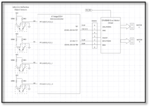
As indicated in the figure above, the IR Shield has four QRE1113 sensors that output to the 3DoT board. The shield’s QRE1113 IR reflectance sensor is comprised of two parts – an IR emitting LED and an IR sensitive phototransistor. When you apply power to the VCC and GND pins, the IR LED inside the sensor will illuminate. A 100Ω resistor is on-board and placed in series with the LED to limit current. A 10kΩ resistor pulls the output pin high, but when the light from the LED is reflected back onto the phototransistor, the voltage at the output will begin to go decrease. The more IR light sensed by the phototransistor, the closer to zero it will go.
These sensors are widely used in line following robots because of how the output varies based on the reflective properties of the material below it. In general, white surfaces reflect much more infrared light than black, so, when directed towards a white surface, the voltage output will be lower than that on a black surface. This is due to the black surfaces absorbing the IR light, which results in the 3DoT board interpreting it as an output of 1 (digital logic HIGH) . When on a white surface, the output will be seen as a 0 (digital logic LOW).
With this in mind, you may see what needs to be done in order to implement the wall following logic that was discussed in the Lab 1 design challenge. To prepare you for Lab 3, please answer the following questions.
Question 1 – As only two IR sensors will be needed for a simplistic wall following algorithm, which motor driver pins should they be connected to? Consider which pins will require the least additional code to implement. Mention any extra steps needed for your choice to work. We want the robot to correct its movement if it runs into a wall and to keep going forward.
Question 2 – What assembly instruction can be used to save a specific bit value from a register? Where is that information saved to?
Why are there so many names for one wire?
One thing you may find confusing, is all the names and numbers associated with each input. Looking at the right sensor we see the somewhat confusing A0 plus PF7(ADC7), IR_R-O. The A0 mnemonic is the name assigned by the Arduino community and the one we would use if we were programming within that Arduino IDE. The second PF7(ADC7) is the name given to the pin by Atmel. It has two mnemonics PF7 and ADC7 because this pin is shared by two peripheral subsystems – GPIO Port F and the Analog to Digital Converter (ADC). We are reading the sensor as a digital input and so the name we want is PF7. Mnemonic IR_R-O is defined in robot3DoT and is equated to PF7. Believe it or not this was done to make the code more readable as it is clear what the pin is being used for.
Logic Operation Review
As we begin to solve more complex problems with our programs, you will find that it is not possible to accomplish the desired output by simply connecting the input directly to the outputs. There will be cases where the inputs need to be manipulated in some way before being sent to the outputs. There may be some decoding or applying boolean logic in our programs. To prepare for that, we will review the basic logic operations that can be performed with the assembly instructions. Keep in mind that all of these operations are bit-wise even when applied to entire registers. Please fill in the tables with the correct outputs.
| Logic Operation | Bit #1 | Bit #2 | Output |
| AND | 0 | 0 | |
| 0 | 1 | ||
| 1 | 0 | ||
| 1 | 1 | ||
| OR | 0 | 0 | |
| 0 | 1 | ||
| 1 | 0 | ||
| 1 | 1 | ||
| EOR (Exclusive OR) | 0 | 0 | |
| 0 | 1 | ||
| 1 | 0 | ||
| 1 | 1 | ||
| COM | 0 | X | |
| 1 | X |
| Logic Operation | Register #1 | Register #2 | Output |
| AND | 01101010 | 11000110 | |
| AND | 0xA8 | 0x75 | |
| OR | 10011101 | 10100110 | |
| EOR | 0x5D | 0xF4 |
Prelab 3 Deliverable(s)
Page 1 – Title Page with Name, lab title, and photo
Page 2 – Answers to questions and completed tables

