Assembly Robot Prelab 6 – Indirect Addressing (SRAM)
Table of Contents
Introduction
The focus of this prelab is to provide you with additional practice with indirect addressing and how it will be used in the labs. We also go over some of the more advanced ways it can be used.
Indirect Addressing
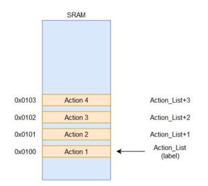
First, we need to review the difference between the direct addressing mode and indirect addressing. For the direct addressing mode (LDS, STS, IN, OUT, etc), the location of the data is fixed. It must be specified directly and is a part of the machine code encoding. This is to provide the CPU with the information that it needs. Because of this, each instruction to load or save to a variable or set of variables is unique. If you need to cycle through the variables as part of a loop, it will require one or more line of code per variable. This can result in pretty lengthy code depending on the implementation. For example, let us say we are working with an SRAM variable called Action_List that is 4 bytes large. Each individual action will be stored at each byte, so we have a total of 4 actions. The way that we can refer to each location is depicted below.
 Action 1 is associated with the SRAM address 0x0100 and the name Action_List. Action 2 is linked to the SRAM address 0x0102 and can be referred to with the name Action_List+1. The rest can be extrapolated from there. In terms of the code that would be needed to load the data for all four actions, it would look something like this.
ldi R16, 0x03                              ldi R16, 0x03
lds R17, Action_List                       lds R17, 0x0100
add R17, R16                               add R17, R16
sts Action_List, R17                       sts 0x0100, R17
lds R17, Action_List+1                     lds R17, 0x0101
add R17, R16                               add R17, R16
sts Action_List, R17          OR           sts 0x0101, R17
lds R17, Action_List+2                     lds R17, 0x0102
add R17, R16                               add R17, R16
sts Action_List, R17                       sts 0x0102, R17
lds R17, Action_List+3                     lds R17, 0x0103
add R17, R16                               add R17, R16
sts Action_List, R17                       sts 0x0103, R17
If a calculation or modification needs to be made to the action values, it would involve another set of 4 to 8 instructions. Overall, it could require a total of 12 or more instructions just to do one action on these variables. If you had to deal with a large number of variables within a loop that repeats a certain number of times, the code could get very unmanageable. This is why the direct addressing mode is suitable for small scale applications but becomes tedious for data processing applications that need to deal with hundreds of thousands of values in a data set.
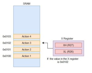
On the other hand, indirect addressing is ideal for dynamically dealing with large sets of data and has no problem scaling as needed. The logic behind how the code needs to be structured is a little more complicated but it will reduce the number of instructions needed. The key detail is that the information about the location of the data is handled within a separate register that is referred to as a pointer. This register can be dynamically modified by the program, so that the location the indirect addressing instruction is using is different. Rather than having the address included within the instruction, the machine code encoding has a value representing which pointer register is being used. An example is shown in the figure below.
 In this situation, we are still dealing with the SRAM variable called Action_List with a total of four actions. The same address values are used (from 0x0100 to 0x0103) but the way we refer to it has changed. Here, we have the X register which is our pointer to the location it will be dealing with. The X register is the register pair of R27 and R26, so whatever value is placed into those two registers will be the SRAM address the indirect addressing instruction uses. From the figure, if you wanted to work with Action 3, the value inside the X register has to be 0x0102. This may seem more involved to handle each value of the list but it allows us to do so much more.
The general structure of the program using indirect addressing will usually be something like the following.
1) Initialize pointer register to the start of the data table or variables to work with.
2) Load data if needed
3) Perform action on data
4) Modify pointer register if needed
5) Store data back if needed
This structure allows us to simplify the example from above into the following.
start:
    ldi R27, 0x01                   ldi XH, HIGH(Action_List)
    ldi R26, 0x00                   ldi XL, LOW(Action_List)
    ldi R16, 0x04                   ldi R16, 0x04
    ldi R17, 0x01                   ldi R17, 0x01
    clr R15                         clr R15
looping:
    ld R18, X                       ld R18, X
    add R18, R17        OR          add R18, R17
    st X, R18                       st X, R18
    add R26, R17                    add XL, R17
    adc R27, R15                    adc XH, R15
    dec R16                         dec R16
    brne looping                    brne looping
You should be able to identify which lines of code correspond to that structure. In this case, the X register is initialized to the start of Action_List. We also prepare the values to add 1 to the value of the action as well as how many times to loop for. From there, the value is loaded into R18 before adding 1 to it and storing it back. The X register is increased by 1 to move onto the next spot before the loop continues. On the second loop, it is now pointing to Action_List+1 or 0x0101 and performs the same action. In this situation, the number of lines of code is only one less than the previous example but it is significantly easier to scale up. If there were now 150 actions in the list, the direct addressing example would have a total of 450 instructions. For the indirect addressing mode, I would only need to change the number of times it would loop for and it would have a total of 12 instructions.
Now that we have covered the basic concept, we can go over some additional details that make more complex applications easier to program.
1) For indirect addressing within SRAM, there are a total of three pointer registers available. This allows you to theoretically be handling three separate locations at once if needed. Most of the time, it will be easier to reuse a single pointer once each location has been dealt with. The pointers are called the X, Y, and Z registers. X is the R27:R26 pair, Y is the R29:R28 pair, and Z is the R31:R30 pair.
2) LD is used to load the data from the location that is indicted by the pointer register. ST is used to store data to the location that is indicated by the pointer register.
3) Modifying the pointer register by 1 within a loop can be accomplished with pre-decrement or post-increment. Pre-decrement will subtract the pointer register by 1 before performing the specific action (load or store). Post-increment will perform the action and then increment afterwards. For example, the code above could be simplified into the following.
st X, R18
add XL, R17        Becomes ---->        st X+, R18
adc XH, R15
This can also be applied to LD as well. It is indicated by adding the sign to the pointer register used. So post-increment with LD would be LD R18, X+. If the value in the X register was 0x0100, the LD instruction would load the data from the SRAM address 0x0100 and then modify the X register to be 0x0101. For pre-decrement, it has a minus sign in front of the pointer register (LD R18, -X).
4) If the pointer register needs to be continually modified by a certain amount, you can utilize the indirect addressing with displacement instructions (LDD or STD). This is only applicable if you need to grab every third value from the data table or something similar. The instruction would look like this – LDD R18, Y+3.
Questions
Question 1 – Assume that an SRAM variable called voltage_data is defined and is initialized. This variable is assigned to the address 0x0104 and has 15 bytes allocated for the data. Using the following code, what is the value within the pointer register after it is executed?
ldi ZH, high(voltage_data+6)
ldi ZL, low(voltage_data+6)
Question 2 – After those lines of code have been executed, our program needs to access the data from the twelfth byte of the variable. Write the code that will modify the pointer register to point at the proper location. Make sure to load the constant that is going to be used into a separate register.
Question 3 – Explain what the following piece of code will do. Cover details such as how many times the code will repeat, how the data is accessed, what is being done to the data, and so on.
ldi YH, high(voltage_data)
ldi YL, low(voltage_data)
ldi R16, 0x1C
ldi R17, 0x05
loop:
    ld R18, Y
    add R18, R17
    st Y+, R18
    dec R16
    brne loop
Question 4 – Assume that the SRAM variable test has been defined and has the following values initialized (0x03, 0x08, 0xA8, 0xF3, and 0x97). Once the following code has been executed, what value will be loaded into R17?
ldi ZH, high(test)
ldi ZL, low(test)
ldi R16, 0x03
clr R18
add ZL, R16
adc ZH, R18
LD R17, Z
Prelab 6 Deliverable(s)
Page 1 – Title Page with Name, lab title, and photo
Page 2 – Answers to questions
