Fall 2018 AT-ST: Manufacturing Design
Author/s: Wendy Guerra (Project Manager)
Introduction
After analyzing the design of AT-ST Generation #1 and the Velociraptor, we came to the conclusion to not incorporate the hip design from the Velociraptor due to the brittleness of the design. Moreover, the injected mold leg model was found difficult to 3D print; since the requirement for AT-ST Generation #1 was to be mass-producible, the design would need to be altered. A solution that shall be explored is to design legs to incorporate the Theo Jansen leg mechanism, as demonstrated in figure 1 of the Theo Jansen BiPed kit model, in order to withstand the weight of a top-heavy robot due to electronics that it will be carrying.
In previous semesters with the BiPed, one of the most difficult things encountered was the leg design in general, including the rotating shaft, along with the weight distribution being accounted for. The idea is to keep the legs as close as possible to allow for a smooth walking motion without the robot tipping over. Center of mass plays a large role in AT-ST considering the load it has holding all the electronics at the top and the spacing of the legs is crucial.
Manufacturing Design
This design is a mixture of previous semesters ideas meshed into one. There were things that seemed to work and others that were not such a good idea. The fabrication of some of the designs were not so successful, but by incorporating different pieces, perhaps this robot will finally be able to walk and complete the mission objectives.
Going from the top down, the head that will be holding all the electronic components will be the MicroFobo head of Spring 2018 3-D printed in ABS.
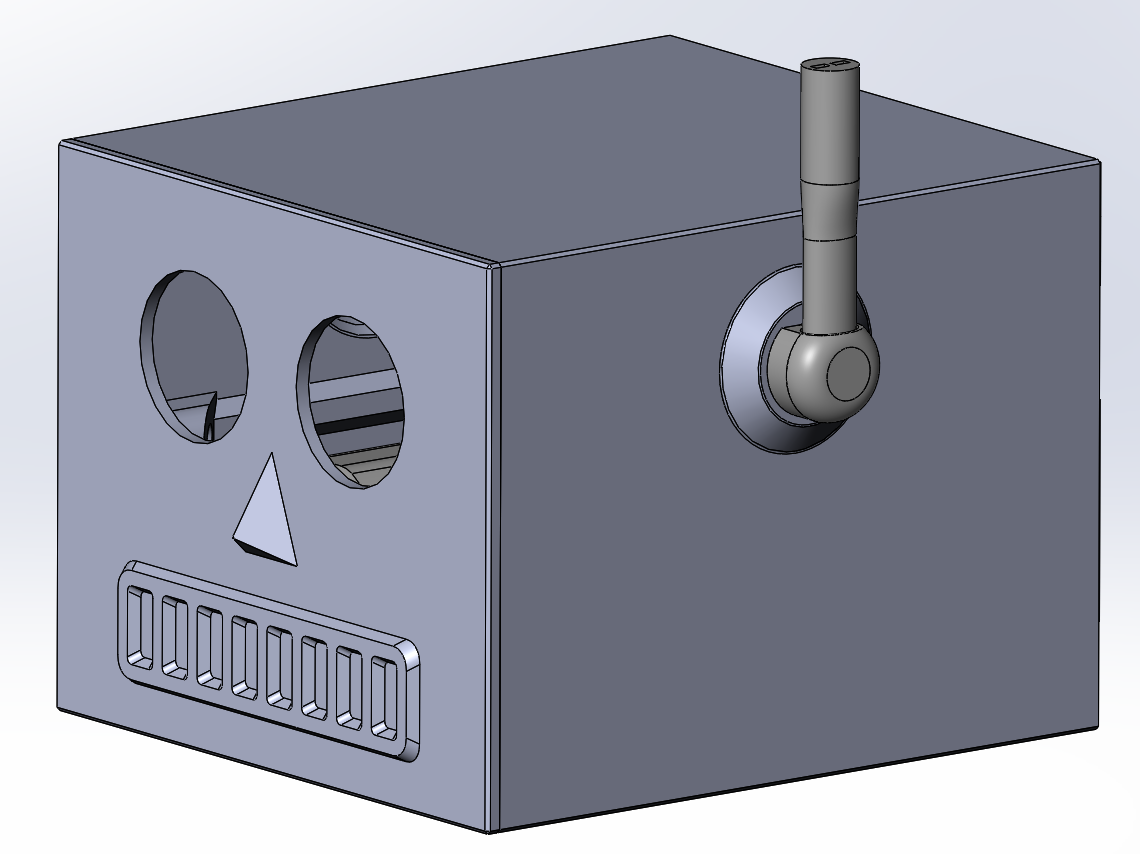
Figure 1: MicroFobo Head
Considering it held everything in place so well for the previous semester, we incorporated this into our design. Following the head will be the neck and body to hold the MicroFobo head up. It will have placeholders for the motors, and also where each leg will be connected to on each side.
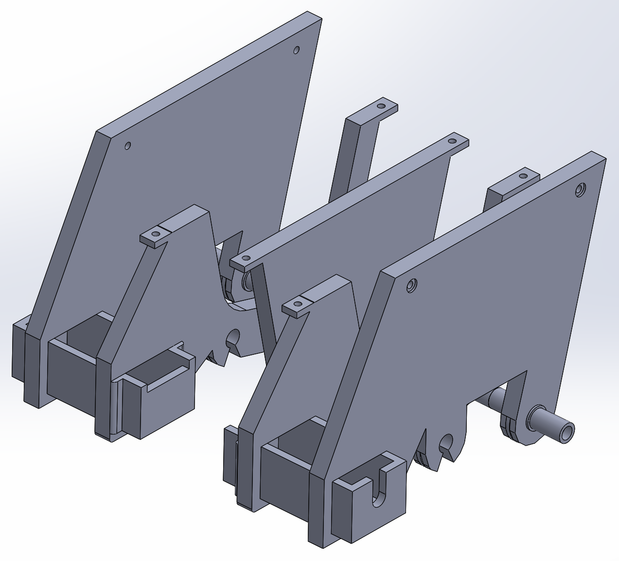
Figure 2: Neck/Body/Motorcase
This design was from AT-ST Spring 2018, but for this design the motors will be closer together and the frame will be directly under the head instead of connecting to the sides of the head. This will be 3-D printed in ABS.
The Theo Jansen BiPed featured a single crank shaft to produce walking and ball bearings which acted as weights to shift weight while walking.

Figure 3: Theo Jansen BiPed
By splitting the shaft down the middle to create 2 shafts, each one could be controlled by a motor. In place of the ball bearings would be a servo placed in the head portion, along with the other electronics, to account for the weight shifting mechanism to have an active walk. Considering the robot will be top-heavy, it is important to have the legs placed close together. The leg design that is incorporated into our design is from BiPed Fall 2016.

Figure 4: Leg Design
Each joint will be connected with screws and bolts, and legs will be laser cut in acrylic. This way, the leg will not have any deformities with the trouble of 3-D printing, especially when it comes to the error with holes that the previous semester had.
Lastly, the feet will be the Theo Jansen BiPed feet design that AT-ST Spring 2018 utilized.
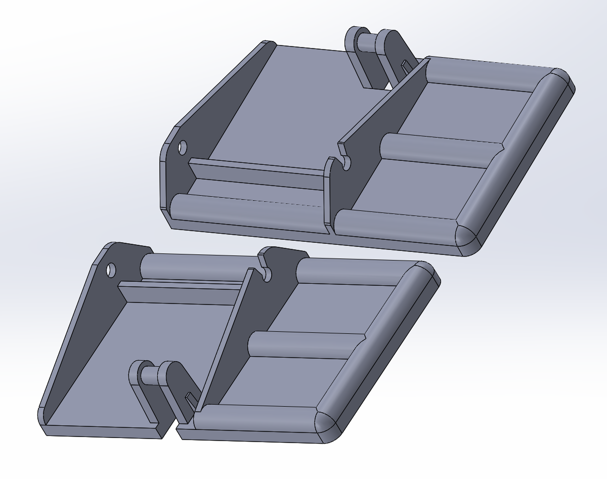
Figure 5: Feet