PCB Schematic Layout

Figure 1: PCB Schematic Layout using EagleCAD
The PCB designed requires multiple headers that will allow the components to connect to the custom 3 dot board. The 2 six pin headers are to connect the DC motors with shaft encoders to the 3 dot board. The motor +/- will go to its own headers which will then connect to the motor drives on the 3 dot board. The headers title absolute are optical sensors that act as absolute encoders. These absolute encoders will send an interrupt signal so the machine knows when the motors have gone a full 360 rotation. The 330 resistor is to make sure that the LED diode in the optical sensors are operational and not burn out. The 100 Kohm resistor is used to replace the previous npn transistor that was used in the previous version of the schematic layout. Instead of having a transistor there to make the optical sensor act as a digital switch to send the interrupt signal, the 100 Kohm resistor does the same while also saving space for the design. Lastly the ultra sonic sensor are connected through the PCB for the AT-ST’s maneuvering.
PCB Design Layout
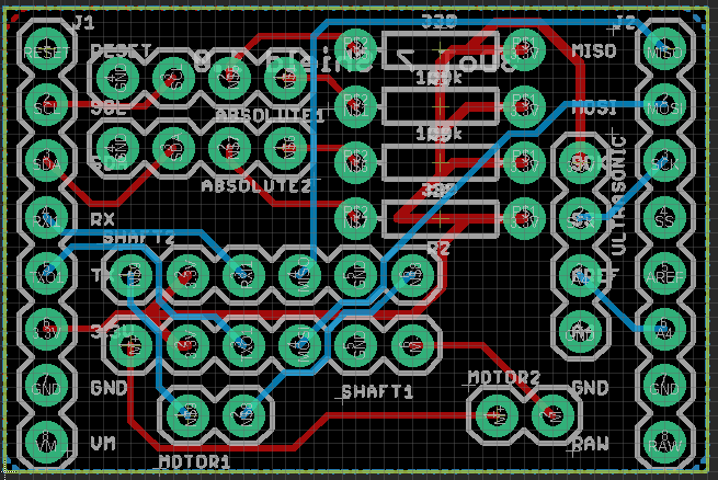
Figure 2: The Layout of the PCB for AT-ST using EagleCAD
All components on the PCB will be through hole headers with 2 330 ohm and 2 100 kohm resistor. Both of the top and bottom layers are labeled ground so there is no need to connect all the ground pins together. The 3.3 V pins are all connected together where the trace lines are wider than the others (16 mm for 3.3 V compared to the 9 mm of the rest).