Spring 2018 AT-ST Gyro
By: Intiser Kabir (Project Manager) and Danny Pham (Manufacturing)
Approved By: Miguel Garcia (Quality Assurance)
Table of Contents
Introduction
Our research on the Gyro is to see if it is a good mechanism to help balance our AT-ST robot. We are 1st going to test how the Gyro calibrates when moved around. After that, we are going to see if the Gyro can help control the head and “tail” feature of our AT-ST robot, which are going to be used as a balancing mechanism. To do so, we are trying to see how Gyro can control Servos to give us an idea how to set up the Gyro-Servo balancing mechanism.
Materials
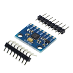
- 1 x MPU-6050 (Gyro)
- 1 x Arduino Uno
- 1 x connection cord
- 1 x Micro Servo
- 4-7 x Wires
- 1 x breadboard (however it might not be needed depending on the type of wires you use)
Testing the MPU6050
Fritzing Diagram
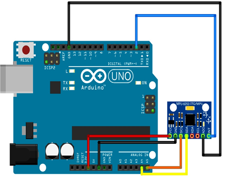
Figure 1: The circuit above is used to see calibration of the Gyro
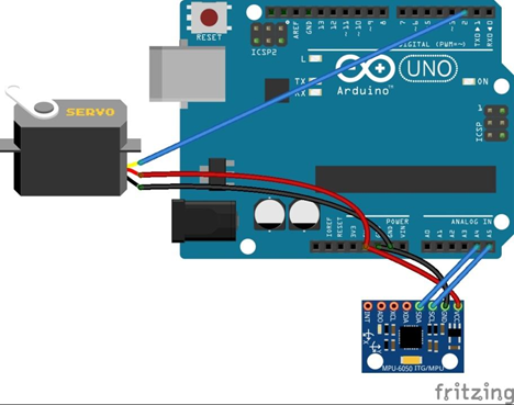
Figure 2: The circuit above is where you control the servo arm with a Gyro
For our build since MPU6050 Wiring:
- SCL – A5
- SDA – A4
- VCC – 3.3V
- GND – GND
- INT – PIN3
- Servo Wiring:
- VCC – 5V
- GND – GND
- Control – PIN3
Instruction
Gyro Calibrations:
- Connect the gyroscope to the Arduino using the fritzing diagram (Figure 1).
- Download the MPU6050 and I2Cdev libraries in the GitHub link in the references below.
- Copy the MPU6050 and I2Cdev folders into the Arduino libraries.
- Now open up the MPU6050_DMP6 file in Arduino under examples.
- Make sure the board and port are selected. Verify and upload the code to the Arduino.
- Open up the serial monitor and set the Baud rate to at least 15000.
- Follow the instructions. Enter a character and the coordinates will be given shortly.
Gyro – Servo Control:
Set up circuit like this:
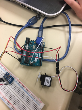
Figure 3: Physical Set Up
MPU6050 Wiring:
- SCL – A5
- SDA – A4
- VCC – 3.3V
- GND – GND
- INT – PIN3
Servo Wiring:
- VCC – 5V
- GND – GND
- Control – PIN3
- Download this Code: https://drive.google.com/file/d/0B0SU0douW9lVenJ0Vng0QlEyUDQ/view
- In order for the sketch to work you will need to install i2cdevlib library to Arduino library folder:https://github.com/jrowberg/i2cdevlib
- Bring the MPU close to servo
- Move MPU around to see the servo around moving around
Watch this video as reference: https://www.youtube.com/watch?v=vSKEH0FwhUE
Results
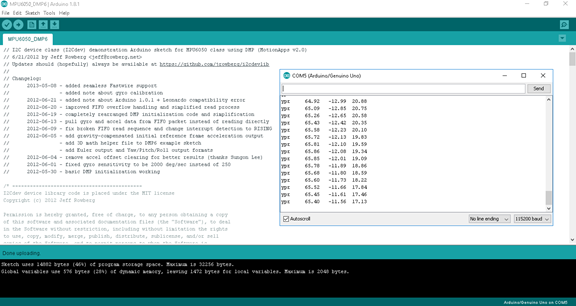
Figure 5: Output of the Calibration code
The calibration tells the x,y,z directions of the gyro.
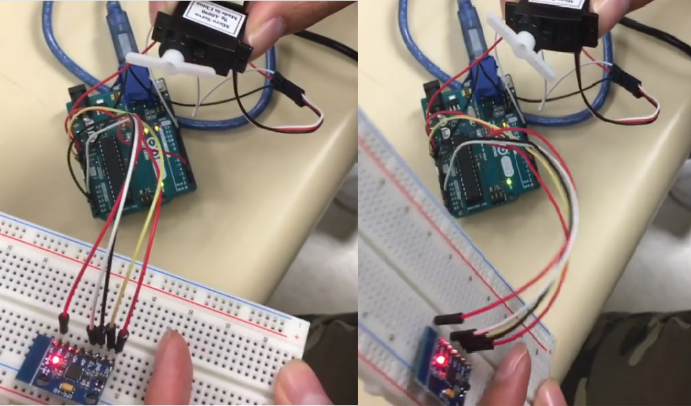
Figure 6: servo arm moves at the same time as the gyro
It is sort of hard to tell from the picture, the servo arm moves depending on the change of position of the gyro just to be aligned with it.
Conclusion
From this research, we can see the Gyro can be useful in our balancing mechanism since we can control the directions the servos move. From the research, we can see how the Gyro can be calibrated when we move it around. We are planning to do more testing regarding our balancing mechanism for a future task using the Gyro.