Spring 2018 AT-ST Sensor Testing
By: Shweta Hebbalkar (Electronics and Control – Hardware)
Verified By: Intiser Kabir (Project Manager)
Approved By: Miguel Garcia (Quality Assurance)
Table of Contents
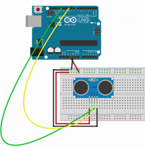
Ultrasonic sensor – HC-SR04
Introduction
As the name implies this device uses an ultrasonic sound to measure the distance between itself and the nearest solid object. Like if we take the nature’s example then it would be like Bats detecting shapes from the sound. So with this key feature has become a staple in our projects because the last thing we want is for our project AT-ST to get the pushed out from the other robots.
Features
- Operating Voltage: 5V DC
- VCC = 5 volt power connection
- Operating Current: 15mA
- TRIG = trigger pin (input)
- Measure Angle: 15°
- ECHO = Echo pin (output)
- Ranging Distance: 2cm
- 4m – GND = Ground
Theoretical Explanation of the ultrasonic sensor
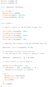
Let’s look in more depth of this ultrasonic sensor so for our project we are using the HC-SR04 and it consists of two ultrasonic transducers one is used as the transmitter and another one is used as a receiver. Now when we normally operate the transmitter sends out a series of ultrasonic pulses remember the receiver despite its proximity does not pick up these pulses because ultrasonic signals are very directional. However, if an object in front of the device it will reflect the signals back to the receiver. The time delay that takes from the transmission and receiving the signal is used to calculate the distance so, for example, a longer delay will be considered as long distance and the shorter time delay will be the shorter distance. Now if we send the 5-volt, 10-microsecond pulse to the device then transmits 8 ultrasonic pulses either at the 40-kilohertz each. The echo pin will output a pulse between 100 and 50 – microsecond to 25 milliseconds and that pulse width is used to calculate the distance it will output a pulse of 38 milliseconds if there is no object detected.
Calculating the distance
To determine the distance ultrasonic signal travel at the speed of sound at 20 degrees Celsius the speed of sounds is 343 meters per second now remember the time we’re measuring with the HC-sr04 is for return trip so we’ll need to divide this in half to calculate the actual distance.
∆t=time delay
c=speed of sound (cm)
D=Distance Measured
D=∆t2*c
As an example
D= (500/2) * 0.0343 = 8.575 cm
Experiment
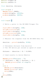
Code
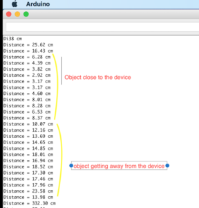
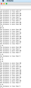
Output
Servo – Ultrasonic #1
Introduction
Servos are combined with the motor and also control electronics; this combination makes an easy to use package. The PWM signals with a periodic time of 20 milliseconds and a duty cycle of one to two milliseconds so five to ten percent. While an on time of one millisecond resents the -90-degree position of the motor shafts. 0-degree positions and the 2 milliseconds the +90-degree position. So we can rotate the shaft a total of 180 degrees.
Features
- Voltage: 4.8~6.0V
- Torque: 3.5kg.cm@4.8V, 4.8kg.cm@6.0V
- Speed: 0.17/60ТА @4.8V;0. 14/60ТА @6.0V
- Size: 38.6×18.8×34.9mm
- Wight: 37 g
- Use Angle: <=160ТА
Code
Output
Servo – Ultrasonic #2
Introduction
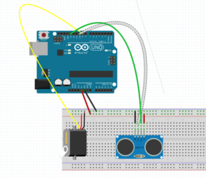
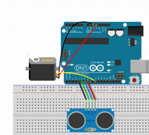
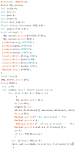
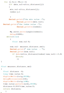
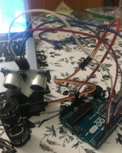
In this experiment, I created an object detector. So this module will scan from 0 to 180 degrees, and once its finish scanning the module will point at the object. If I displace the object, then the module will scan again from 0 to 180 degrees and trying to look for an object. This is one of the ideas for our project trying to avoid the other robots from the maze.
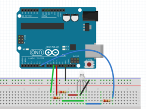
Fritzing diagram
Code
Output
RGB led
Introduction
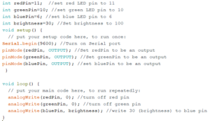
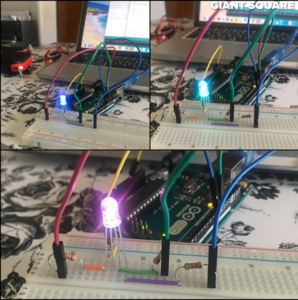
Formerly, we were going integrate the color sensor to our robot. In order to require the decision either to take right, left, or keep going forward. Now, the color sensor is not required for our project because we change our maze requirements. But before that, I am going to explain the RGB Led to help me understand the color sensor little better. So, an RGB LED is a three LED’s in one basically 4 LED. This is a basic experiment to learn new circuit components and new programming skills.
Code
Output
Dc Motor
DC Motors that operate on direct current as opposed to motors, which operate on alternating current. We are using the small dc Motors for our project in order to move let’s look into how dc motor works. The shaft of the motor, the part that rotates is referred to an armature. On the armature, there are coils of wire these coils are connected to the commutator. The connections to the commutator are called the brushes, where the positive and negative voltage is applied. On the outside of the motor, there is a permanent magnet arranged in opposite magnetic polarity, now when dc current is applied to the commutator it sets up a magnetic field inside the coil. The coil magnets interact with permanent magnets causing the armature to rotate, now as the armature rotates the polarity is continually reversed generating the magnetic field to be reversed and the rotations to continue.
A motor driver module helps the dc motor with an Arduino, which means that dc motor will get the more current in order to, work, in other words, a current amplifier. So a motor driver is a breakout board, which consists of an L293D IC, the main purpose of the motor driver is to take a low current signal and convert it to a high current signal.
Conclusion
Due to some feedback from the Professor, we are not using RGB and will be using UV sensors with IR LEDs. We are using Ultrasonic as an avoidance mechanism. The DC motor is used to move our legs. We are planning to use servos to help control the center of gravity.
Reference
- https://cdn.sparkfun.com/datasheets/Sensors/Proximity/HCSR04.pdf
- https://www.sainsmart.com/products/ultrasonic-ranging-detector-mod-hc-sr04-distance-sensor
- https://components101.com/ultrasonic-sensor-working-pinout-datasheet
- https://www.radioshack.com/products/radioshack-standard-servo
- https://www.sparkfun.com/datasheets/Components/YSL-R596CR3G4B5C-C10.pdf
- https://nationalmaglab.org/education/magnet-academy/watch-play/interactive/dc-motor

