Spring 2018 AT-ST Shaft Encoder
By: Joseph Cho (Mission, Systems, and Testing)
Verified By: Initiser Kabir (Project Manager)
Approved By: Miguel Garcia (Quality Assurance)
Table of Contents
Introduction
For our AT-ST project, the two motors on the legs have to be precise. In order to know the exact location of the turns, shaft encoders have to be added. The shaft encoders that have been chosen will be using a magnetic shaft encoder. The magnetic shaft encoder uses hall effect to determine the rotation of the axle.
Hall Effect
The shaft encoder is packaged with a 6 pole magnetic disk that is used to provide the magnetic field. Hall effect is observed when magnetic field causes the small current of elections to deviate and produce Hall voltage. When the magnetic disk rotates, it causes changes in magnetic fields. The hall effect latch (TLE4946-2K) inside the shaft encoder will sense these changes and output values. Using these output values, the position of the axle will be determined.
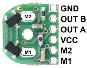
Connections on shaft encoder
Description:
The shaft encoder has 6 pins. The M1 and M2 pins on the right are for powering the motor. The motor will be connected directly to the shaft encoder by soldering M1 and M2 holes in the center of the board. GND and VCC are used for powering the board. Output A and Output B are the outputs from the two TLE4946-2K hall effect latches.
After contacting the previous blog post author, the decision to use only one of the output has been made. The shaft encoder has two hall effect latches for accuracy and using only one of them is sufficient enough for our uses. A trade-off study may be done to test the amount of current used and the accuracy of the shaft encoder.
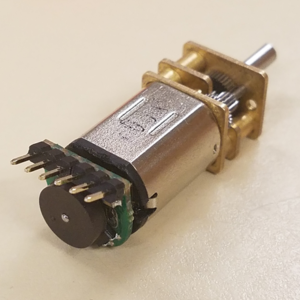
GearMotor with Shaft Encoder
The image above shows that the shaft encoder is soldered onto the motor directly with male headers.
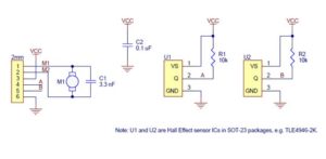
Schematic of Shaft Encoder
Description
The schematic shows the connections of the shaft encoder. The motor will be soldered onto M1 and M2 which will be powered by pin 1 and pin 2 of the shaft encoder. Pin 3 and pin 4 are used for Vcc and Ground. Pin 4 and pin 5 are outputs of the shaft encoder hall effect readings.
Reference
- https://www.pololu.com/product/3081/specs
- https://www.pololu.com/file/0J814/magnetic-encoder-kit-for-micro-metal-gearmotors-schematic.pdf
- https://www.pololu.com/file/0J815/TLE4946-2K.pdf
- https://www.arxterra.com/motor-shaft-encoder-trade-off-study/
- https://www.electronics-tutorials.ws/electromagnetism/hall-effect.html
- https://www.pololu.com/product/3081/specs#lightbox-picture0J6835;main-pictures


