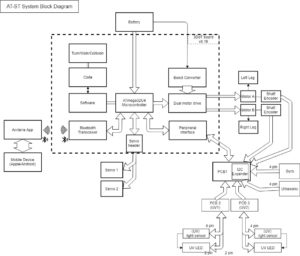
Spring 2018 AT-ST System Block Diagram
By: Joseph Cho (Mission, Systems, and Testing)
Verified By: Initiser Kabir (Project Manager)
Approved By: Miguel Garcia (Quality Assurance)
Table of Contents
Introduction
The system block diagram is made to visually show the systems of our product, AT-ST. The 3DoT board is the center of the system consisting the microprocessor and motor headers. There will be custom PCB that are connected to the 3DoT board for telemetry and sensors.
System Block Diagram
Description
The System block diagram above for AT-ST help visualize the system of the AT-ST. The 3DoT board uses ATmega32U4 as the microcontroller. The 3DoT board consists of microcontroller, bluetooth transceiver, servo header and dual motor driver. The 3DoT board (v6) will also be connected to the servos, motors and main custom PCB. PCB1 will be the master PCB that routes all input and output for the sensors. PCB 2 and PCB 3 are used for UV sensors which will be connected to the I2C expander on PCB 1. Bluetooth transceiver will connect to a mobile device using the Arxterra app via bluetooth.
I2C Expander
The UV sensors has to be connected to the I2C expander because the I2C address of same sensors will be overlapping. If we were to use a metaphor of I2C addresses, they are different phone numbers that are used to communicate. If two people were to have the same phone number, there would be a major problem. Signals may be overlapped, misguided, and destroyed when the addresses overlap each other. The I2C address of the Si1145 (UV sensor) is set on 0x60, so I2C expander has to be used to change the single address into two different addresses. One thing to be cautious about is that the new address should not overlap the address of gyroscope (0x68 or 0x69).

