By: Joseph Cho (Missions, Systems, and Testing)
Verified By: Intiser Kabir (Project Manager)
Approved By: Miguel Garcia (Quality Assurance)
Table of Contents
Introduction
The interface matrix is used to navigate the pin allocations. The 3DoT board will be the main focus on the interface matrix since the AT-ST is using Atmega32(3DoT) as the microprocessor. The interface matrices are divided into four parts: 3DoT board, PCB1, PCB2, and PCB3. PCB1 is used as master PCB for I2C expansion and I/O. PCB2 and PCB3 are each used for UV sensor.
Interface Matrices
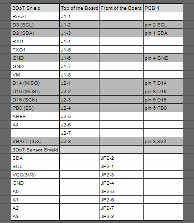
Figure 1: 3DoT Board interface
Description: The AT-ST will be utilizing 8 pins on top of the 3DoT board. Pin 1 SDA and pin 2 SCL will be used for the I2C bus to communicate with the sensors (two UV sensor and one gyroscope). Pin 3 3v3 and pin 4 GND will be used for powering and grounding the components.
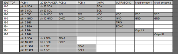
Figure 2: Custom PCB #1
Description: PCB1 will have an I2C expander which will be used for the two UV sensors which have an overlapping I2C address. PCB 1 will have 4 digital pins used for gyroscope, ultrasonic, and two shaft encoders. The first column is there to locate where these pins will be linked to on the 3DoT board.
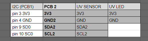
Figure 3: Custom PCB #2
Description: PCB2 will be mounting an UV sensor and an LED. UV sensor uses 4 pins total. The SDA and SCL will be connecting to the I2C expander to place them into different addresses.
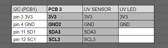
Figure 4: PCB#3 is a duplicate of PCB#2.
Description: These charts were created using Excel. It shows all the ports/pins that are available to use for our robot. We are using the 3DoT Board and 3 custom made 3DoT Boards for this assignment.
Summary
The interface matrix above shows the allocations of the components to the 3DoT board. List of connections to PCB1: ultrasonic sensor, gyroscope, shaft encoder 1, shaft encoder 2, PCB2 and PCB3.
On PCB1, there will be an I2C expander for the two UV sensors that share the same I2C address (0x60). The gyroscope has I2C address of 0x68 or 0x69, so it will not conflict with the UV sensor. PCB2 and PCB3 will be connected to PCB1 to utilize the I2C expander.
List of connections that are not shown in the interface matrix: servo header connecting to two servos and the motor driver connecting to two motors. The figure below shows an older version of the 3DoT board that shows the I/O headers. The new version of the 3DoT board has the motor driver, Bluetooth, and servo headers integrated internally, so they are not listed on the interface matrix.
3DoT Board Schematic (v6)
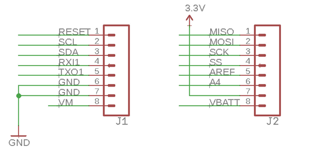
Figure 5: Pinout of 3DoT board (Top of the board)
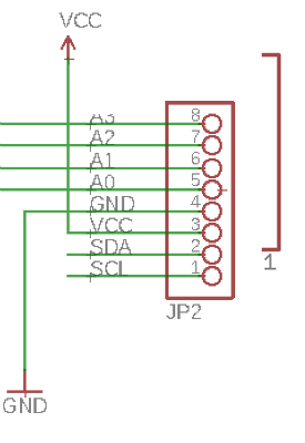
Figure 6: Pinout of 3DoT board (Front of the board)
References
- http://web.csulb.edu/~hill/ee400d/Technical%20Training%20Series/3DoT/Schematic_v5_03.png
- https://drive.google.com/file/d/1_LwpGM1zrkt5YZ9BzRYxAptbZaCNPex_/view?usp=sharing
- https://cdn.sparkfun.com/datasheets/Sensors/Proximity/HCSR04.pdf
- https://www.arxterra.com/preliminary-design-document-2/#Electronic_8211_Interface_Diagram
- https://drive.google.com/file/d/1DA1CZgHypD5G3zjo2Mv4DEfLkzXKSQLu/view?usp=sharing
- https://docs.google.com/spreadsheets/d/1khUBCWJKz3PyFoB2Xp1CngnZKynNM2OerlcSHGMgjUc/edit?usp=sharing
- https://learn.adafruit.com/i2c-addresses/the-list