Auto Leveling Design
By Greg Rios – 3D Modeling
In order to implement auto leveling to the new Sasha, one must first come up with a design that will be easily attached to the current frame or printed parts. Not having to replace parts will help with reduce material being used and be able to finish in a timely manner. Knowing the location where auto leveling components will be located is very important. Incorrect placement will not only waste material but also a lot of time, in case of having to re-design the part and to re-print.
The location I selected was next to the x-carriage and hotend mounts. The reason I decided on this location was because since the switch needs to travel to different parts of the bed, the logical place to put it was somewhere near the x-carriage. SolidWorks was used to design the servo mount, which will hold the servo (TowerPro SG90 9G Mini Servo) next to the hotend mounts with two M3 screws. The other part designed was the servo arm that will allow extend when needed and retract when done probing points on the heated bed. Before any design, a blueprint (or quick drawing) needs to be done so you have measurements of where you plan on putting the mount to make sure that nothing gets on the way when printing and knowing needed clearance when mounting. I also took measurements of the servo and micro-switch, to have dimensions of each, which will help on designing both mount and servo arm. This will allow a proper fitting when parts are printed out.
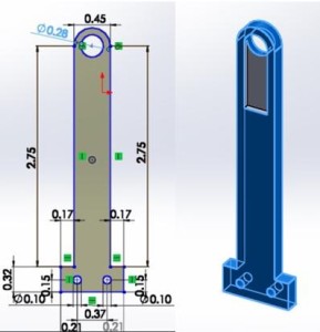
In SolidWorks an outline for the servo arm was drawn and given measurements in order to be able to fit properly on the servo and micro-switch. A caliper was very important tool to be able to get precise dimensions. After front plane was completed with the correct measurements were implemented, it was time to extrude to 5mm thickness. I did not want to use M3 bolts to attach the micro-switch to the arm because we were running short on supplies. I decided to go with zip ties instead, hence the two holes at the bottom of the arm. These had to be the same distance as in the micro-switch.
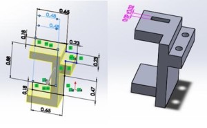
Another important part that needed to be designed was the servo mount. After deciding on the proper dimensions for the servo mount things were starting to come together. The servo mount was also designed to be an easy installation with the least amount of installation difficulties. Caliper was again used to make sure that the mount had enough clearance for the servo. I did however decided to go a little smaller than what the actual measurement I got from the caliper; this was done so that the servo would have a snug fit instead of being loose. I also decided to add an opening that will allow wires from the servo to come out of. All that needed to be after part was printed was to sand the mount and it fit without a glitch.
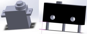
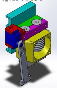
Once both Servo mount and arm were completed, I wanted to see how all parts were going to work together. In SolidWorks there is an option where parts that are created can be assembled. But in order to be able to have a simulator, additional parts needed to be created. I create parts for the servo and micro-switch (OMRON ELECTRONIC COMPONENTS SS-5), these parts had to be precise in measurements that would fit perfectly with mount and arm in SolidWorks, if parts are not precise they will not be able to mate properly error messages would come up on SolidWorks when trying to assemble.
After several hours of adjusting various parts in order to not receive any errors on SolidWorks I was able to assemble it properly and even learned how to use animation on SolidWorks to simulate how parts were going to act on the x-carriage. If you would like to see the video please click link below
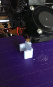
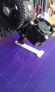
Following picture shows my personal 3D printer, printing both servo arm and mount.
https://www.youtube.com/watch?v=yIJ0AzV6SuI&feature=youtu.be

