Biped/Spring/2019
Biped Body SolidWorks Models
Author: Connor Hearn
Table of Contents
Introduction
The purpose of the Biped’s body is to house the 3Dot board, two motors, and connect to the legs. The design was made simple to have the body do its basic functions.
SolidWorks Body Model Iterations
The first iteration of the body is very basic. The holes in the side were created based off of the dimensions of the legs. These holes are where the legs are connected and bolted to the side of the body. One motor is closer to these holes than the other because the way the legs were designed. This means that the center of mass is closer to the front. The distance from the leg holes to the motor were made based off of the length of the crank that is used to turn the legs which give them the walking motion. The motors that were used were the 200:1 plastic gearmotors. The motors would slide in to the cut outs made specifically for the main shaft and secondary shaft that is located below it. It would be suspended within the body because of the support from the shaft cut outs and the extruded wall created behind it. Space was left under the motors for the addition and implementation of any encoders. This version was 3D printed at the library.
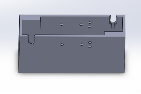
Figure 1. The first iteration of the body.
The second iteration of the body added partitions between the 3Dot board and the motors. While the motors were held in place in the first version, the 3Dot board was not. With the consideration of the nuts that would be used to secure the legs into place on the side of the body, the 3Dot board was not able to be secured to the walls of the body. So while the problem of the 3Dot board not being secured still remained, the new partitions added some support to the 3Dot board to give it a slightly more security than before. The partitions also featured slits which would allow for any wires from the motors to be connected to the 3Dot board or PCB.
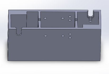
Figure 2. The second iteration of the body. Partitions were added.
The third and final iteration of the semester, modifications were made to implement the new motors that would be used. These motors are the 180:1 mini plastic gearmotors. The reason for the change was because the 200:1 gearmotors could not be found with an encoder while the 180:1 mini gearmotors did. The partitions and support had to be changed according to the new motors. While the new motors were thinner, they were also wider. Since the amount of weight put on the legs should be kept to a minimum, the customer wanted to implement a truss structure on the body to get rid if any unnecessary weight.
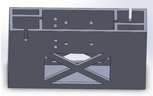
Figure 3. The third iteration of the body. Accounts for new motors and added truss structure to decrease weight.
Lastly, to keep the new motors suspended within the body and keep the motor shafts in place, shelves were created within the section that holds the motor. This is because the 180:1 gearmotors have an extruded rim around it allowing for it to be propped up by these supporting shelves. The shelves are located on both sides of the motor section.
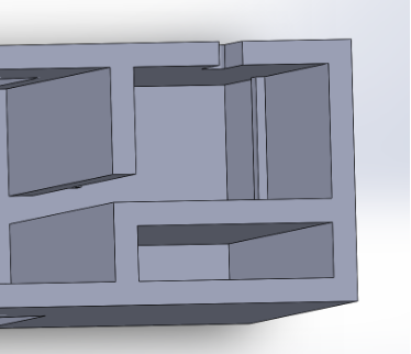
Figure 4. Shelves were added to the motor compartment to keep it suspended.
Conclusion
All of the iterations of the body were kept fairly simple and would allow the body to fulfill its purpose. While the dimensions are based off of the specifications for the new gearmotors, it has not been tested to see whether they would fit well. The final iteration has not been 3D printed either. More work in the future should be done on finding a way to get the 3Dot board secured within the body and finding more ways to cut down on weight.