Build-A-Block Generation 1
Summary Blog Post
Author/s:
- Parker Anderson (Mechanical)
- Grace Hutchinson (Project Manager/ Missions, Systems, & Test)
- Brandon Serna (Electrical)
Table of Contents
Executive Summary
by: Grace Hutchinson
Build-A-Block is quite literally a game changer, as it will improve the way you experience the game of Jenga. No more losing because of shaky hands and lacking hand eye coordination, this robot will allow you to play with ease by building the Jenga Tower, maneuvering around the tower, selecting and removing blocks, and stacking them right where they belong. This is all done with the help of the 3DoT and the ArxRobot app, all you need is Jenga and a smartphone!
Program and Project Objectives
by: Grace Hutchinson
Program Objectives
The Robot Company (TRC) will be releasing its 2020 line-up of toy robots and associated games to the select public at the Robo-Toy convention in Long Beach, CA on May 11, 2020. The Build-A-Block team must create laser-cut prototypes to be shown at the convention before full public release in November 2020. The newest ArxRobot smart phone application and the Arxterra internet applications will also be featured, thus allowing children to play games all around the world.
To allow for decreased electronics cost, all TRC robots will have a 3DoT board incorporated. This board has been specially developed by our Electronics R&D Section. Any modifications of electronics is limited to custom 3DoT shields as required by the unique project objectives of the Build-A-Block robot.
The Marketing Division has set our target demographic as children between the ages of 7 and 13, with a median (target) age of 11. To decrease production costs, please keep robots as small as possible, consistent with our other objectives. As with all our products, all safety, environmental, and other applicable standards shall be met. Remember, all children, including the disabled are our most important stakeholders. Our Manufacturing Division has also asked me to remind you that Manufacturability and Repairability best practices must be followed.
Project Objectives
The objective of Build-A-Block is to play a game of Jenga using a robot. As specified by the Program objectives, there will be a smartphone control integrated that will allow users full authority over the 3Dot Goliath and robotic arm. The game of Jenga will be played on a well built and level kitchen or dining room table.
The Build-A-Block is the 8th generation of the Goliath series of rovers, including the last generation MicroDozer design. This generation will introduce a new concept of combining a robotic hand with a crane thus allowing Build-A-Block the capabilities to grab, push, pull, and build. The mobile robotic arm combined with the sturdy Goliath base will allow the user up, down, forward, and backward range of motion without tipping over while accomplishing its assigned objective.
Mission Profile
by: Grace Hutchinson
Build-A-Block should be able to build a full Jenga tower and then proceed to push and pull singular blocks from the tower using the claw, allowing the user to play a game of Jenga! The movement of the 3Dot Build-A-Block shall be controlled by the user on their smartphone using the ArxRobot app. Build-A-Block will be lifting the standard size wooden Jenga blocks (dimensions of 14 x 24 x 72 mm and weight of 10 grams) and users will follow the rules as marketed by Hasbro.
Build-A-Block will begin by building a Jenga tower (dimensions of 224 x 24 x 72 mm with 48 blocks in groups of 3 with 16 levels), layering block by block in rows of three. Next, the robot will be able to grab singular blocks from the sides of the tower and place them on top of the tower. Finally the robot will be able to push and pull blocks from the middle of the stack to loosen them and grab to place them on top of the tower, all while the tower structure remains intact.
Project Features
by: Parker Anderson (Solidworks Images) and Grace Hutchinson (Explanation)
The main elements of the Build-A-Block robot are the 3D printed Goliath base combined with the laser cut wooden arm and claw. The sturdy Goliath offers a strong and fashionable base and allows the robotic arm to navigate with ease during a game of Jenga.
The robotic arm consists of two servos, one that controls the up/down motion, and the other for forward/backward. The four main joints on the arm offer support without unnecessary weight, and this allows the arm to reach a distance up to 270 mm, all without tipping over or breaking!
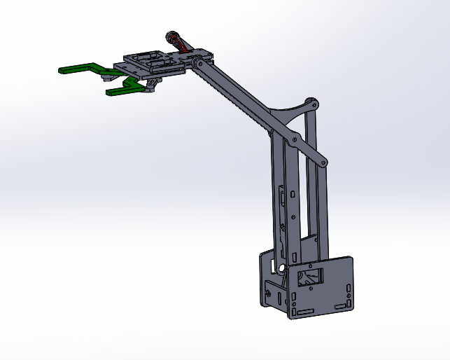
Figure 1. Build-A-Block Arm Design
The robotic claw also consists of two servos, as they allow for each side of the claw to control the open/close motion without affecting the behavior of the other side. The claw has been designed specifically to grab Jenga blocks length wise, with rubber tips and force sensors to ensure the block is gripped substantially.
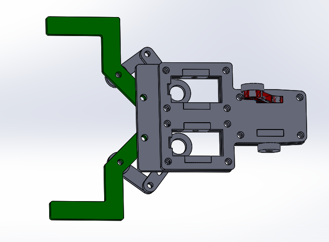
Figure 2. Claw Design for Two Servos
Requirements
by: Grace Hutchinson
The Build-A-Block requirements are divided into Level 1 and Level 2. With L1 we list basic requirements that do not imply design, but rather what the robot shall, should, and will be able to do from a non-technical background. In L2 we elaborate on the necessary design components needed in order to implement every requirement from L1, with specifics to design in firmware and hardware.
Engineering Standards and Constraints
by: Grace Hutchinson
Applicable Engineering Standards
- IEEE 29148-2018 – ISO/IEC/IEEE Approved Draft International Standard – Systems and Software Engineering — Life Cycle Processes –Requirements Engineering
- Bluetooth Special Interest Group (SIG) Standard (supersedes IEEE 802.15.1)
- C++ standard (ISO/IEC 14882:1998)
- NXP Semiconductor, UM10204, I2C-bus specification and user manual
- ATmega16U4/ATmega32U4, 8-bit Microcontroller with 16/32K bytes of ISP Flash and USB Controller datasheet section datasheet, Section 18, USART
- USB 2.0 Specification released on April 27, 2000, usb_20_20180904.zip
Environmental, Health, and Safety (EH&S) Standards
- CSULB College of Engineering (COE) Safety Resources — General Safety Information — Electrical Safety, Chemical Inventory — Electrical Engineering — CSULB Hazardous Material Inventory — Lead Solder
- IEEE National Electrical Safety Code (NESC)
- NCEES Fundamental Handbook (FE) Reference Handbook
- ASTM F963-17, The Standard Consumer Safety Specification for Toy Safety
Program & Project Level 1 Requirements
by: Grace Hutchinson
L1.1 Build-A-Block shall be completed by 05/11/2020
L1.2 When the arm is moved to the starting position, where the arm is retracted and the claw is pulled back to the base, or if the arm is moved to be fully extended, the treads on the base of Build-A-Block shall remain flat against the surface with error up to 5 degrees
L1.3 The Build-A-Block arm, claw, and base modules shall have a disassemble and assemble time of 40 minutes
L1.4 The Build-A-Block budget shall not exceed $550
L1.5 The Build-A-Block shall not exceed a mass of 2000 grams
L1.6 The Build-A-Block base will be 3D printed
L1.7 The Build-A-Block arm and claw will be laser cut
L1.8 As specified in the Mission Profile the game of Jenga is played on a flat table, so Build-A-Block shall be able to travel on a wood table
L1.9 The base of Build-A-Block shall be able to turn in either direction of 0 to 360 degrees with error up to 15 degrees
L1.10 The Build-A-Block arm shall have the control accuracy able to reach down to Jenga Block for the claw to “close” on the block
L1.11 The Build-A-Block claw shall be able to grip a Jenga block length wise
L1.12 The Build-A-Block arm shall be able to lift a Jenga Block up to a height between 100 mm and 275 mm
L1.13 Build-A-Block shall be able to place wooden blocks in the user defined location
L1.14 Build-A-Block should be able to build a full size Jenga tower, with dimensions specified in the Mission Profile
L1.15 In order to begin a “turn” the robot claw should be able to push a singular Jenga block to remove it from a Jenga Tower
L1.16 In order to begin a “turn” the robot claw should be able to pull a singular Jenga block to remove it from a Jenga Tower
L1.17 In order to complete a “turn” the fully assembled robot should be able to stack a Jenga Block on top of a Jenga tower
L1.18 Build-A-Block will have a custom servo shield designed
L1.19 The Build-A-Block arm forward/backward/ up/down movement shall be controllable from a user smartphone using sliders with the ArxRobot App
L1.20 The Build-A-Block claw open/close movement shall be controllable from a user smartphone using sliders with the ArxRobot App
L1.21 The Build-A-Block base forward/backward/ right/left movement shall be controllable from a user smartphone using sliders with the ArxRobot App
L1.22 The fully assembled robot will utilize the 3DoT board
L1.23 Build-A-Block shall not exceed a power consumption of 1000 mA
System/Subsystem/Specifications Level 2 Requirements
by: Grace Hutchinson
L2.1 Build-A-Block shall be demonstrated through Zoom on 05/11/2020
L2.2 The full Build-A-Block disassemble time shall not exceed 20 minutes
L2.3 The full Build-A-Block assemble time shall not exceed 20 minutes
L2.4 The cost of Build-A-Block including materials, circuit components, servos, motors, batteries, and everything listed on the cost report shall not exceed $550
L2.5 The arm and claw of Build-A-Block shall be laser cut on 1/8 inch wood
L2.6 The base and arm base attachment of Build-A-Block shall be 3D printed
L2.7 The Build-A-Block arm shall be attached to the middle of the Goliath base
L2.8 Build-A-Block shall have a 200 gram counterweight attached to the back of the base to keep the treads flat against the surface
L2.9 The wheels shall use two 5V 200 RPM metal gear motors for base motion and turning capabilities
L2.10 The robot claw will be designed in Solidworks to have two separate extensions with 2 MG90 servos that control the open/close movement of each side
L2.11 The 3 MG90 servos will be powered by an external 5V source
L2.12 The V3 robot claw will be designed to have rubber grip attached to the tips for gripping Jenga blocks
L2.13 The Build-A-Block arm shall operate with 2 MG90 servos, the first for the overall arm up/down motion and second for the overall arm forward/backward motion
L2.14 The Build-A-Block claw shall operate with 1 MG90 servo for the claw to open/close
L2.15 The Build-A-Block claw should implement the Adafruit TOF Sensor to control claw force to grab Jenga blocks without dropping them
L2.16 The robot claw should implement the Adafruit TOF Sensor to control claw force to only release Jenga blocks when placed in the desired user location
L2.17 The tip of the Build-A-Block claw should be designed to “push” blocks in the middle columns of the Jenga Tower to begin a turn
L2.18 The Build-A-Block claw should be designed to “pull” blocks from the outside columns of the Jenga Tower to begin a turn
L2.19 The Build-A-Block should stack blocks in 12 rows of 3 to create a full height Jenga tower within 10 minutes
L2.20 Once a block has been removed the robot should be able to place it on top of the tower in the correct orientation to complete a full “turn” in a game of Jenga
L2.21 In order to stack Jenga blocks higher during a “turn”, the Build-A-Block arm shall be able to reach a maximum height of 270 mm
L2.22 The robot will use a soldered Bluetooth-module to communicate with the smartphone ArxRobot app
L2.23 The Command and Telemetry controls of the ArxRobot app shall have sliders to govern the open/close movement of the claw without outside assistance
L2.24 The Command and Telemetry controls of the ArxRobot app shall have sliders to govern the up/down/forward/backward movement of the arm without outside assistance
L2.25 The Command and Telemetry controls of the ArxRobot app shall have sliders to govern the forward/backward/turning motion of the base without outside assistance
L2.26 The custom PCB will be designed using EagleCAD software
L2.27 The circuit components of the custom PCB shall include an Adafruit Servo Shield, Infineon MOSFET, 10 K Ohm resistor, 220 Ohm resistor, 10 microF SMF capacitor, 470 microF SMD capacitor, short feather male pin headers, and Adafruit Time of Flight Sensor
L2.28 The circuit components of the custom PCB shall be soldered on
L2.29 The custom designed shield will include the Adafruit 16-Channel 12-bit PWM/Servo Shield and Adafruit Time of Flight Sensor
L2.30 The custom PCB will be mounted on top of the Build-A-Block base behind the arm
L2.31 The 3DoT will be mounted inside the Build-A-Block base below the arm base attachment
L2.32 The 3.3 V supply from the 3DoT will power the 2 motors in the base of the Build-A-Block and the Adafruit Time of Flight Sensor
Allocated Requirements / System Resource Reports
by: Brandon Serna (power allocation) and Grace Hutchinson (descriptions)
The allocated requirements were tracked and noted throughout the semester in order to produce a robot that used appropriate mass and power. Each allocation report consists of estimated measurements, actual measurements, uncertainty to produce a margin, totals for estimated and measured, as well and contingency based on the total allocations.
by: Brandon Serna
The measured mass came under the expected mass mainly because we used a cheap, small scale that we purchased off Amazon as opposed to the Makers Society scale that we used to measure the V1 arm. In addition to the Makers Society scale having a higher accuracy and resolution compared to the scale we purchased, it could also support weights up to more 1kg, which unfortunately we needed due to the Goliath being heavier than 1kg. Therefore, we had to use the Fall 2019 Goliath and Spring 2019 Goliath as a reference for the measurement of the Goliath and the Metal Gear Motors.
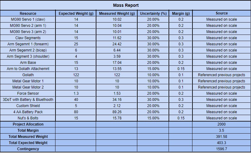
Figure 3. Build-A-Block Mass Report
by: Brandon Serna
The total power allocation was a result of measuring, estimating and referencing current draws used by the ICs, servos, and the 3DoT. Because we’re only using one servo at any given time, each MG90S servo has a max operating current of 250mA, but when measured with a digital multimeter gave us a current draw of around 230-240mA. Each output pin on the servo drive is capable of 25mA, resulting the 75mA current draw for operating 3 servos. The 3DoT will both operate the motors for the Goliath and power the PCA9685 Servo Driver with 3.3V logic. The servos will be powered by a 5V external battery pack consisting of 4 AA batteries in series. The current draw from the motors comes from Fall 2018 Goliath due to us not having access to the motors within the Goliath we borrowed from AOSA.
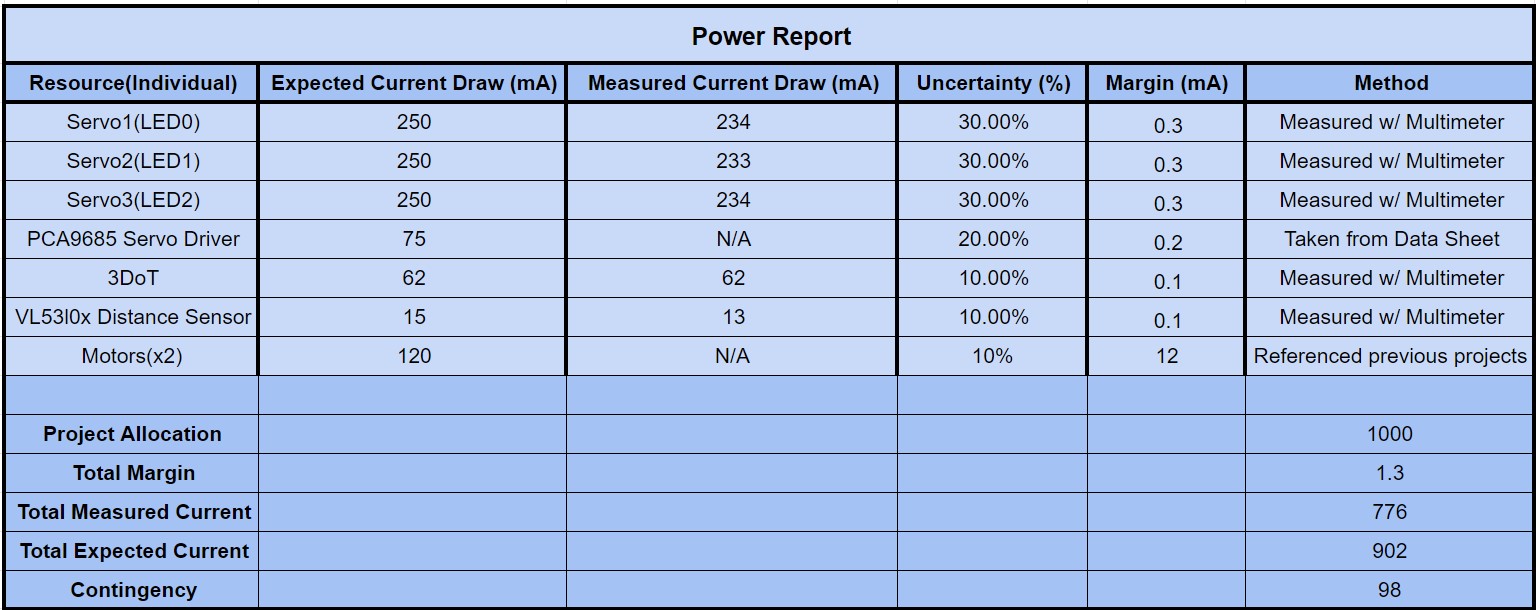
Figure 4. Build-A-Block Power Report
Project Report
by: Grace Hutchinson
In this section the project was organized into different tables and block diagrams to allow for a better flow in organization. The PBS described the goal products of the project, the WBS described the work necessary in order to meet the set goals, the updated cost breakdown kept the team within budget, the Schedule combined everything into one large table, and the Burndown expressed how everything in the Schedule was realistically completed.
Project WBS and PBS
by: Brandon Serna and Grace Hutchinson
Work Breakdown Structure
The Build-A-Block Work Breakdown Structure (WBS) shows the robot progress and work shared by group members and is divided into Missions, Systems & Test, Mechanical, and Electronics & Controls.
The MST will handle the configuration of the ArxRobot app to the robot base, arm, and claw components. The cost analysis covers the budget for each different version and prototype, and the system requirements define the Level 1 and 2 specifics for the robot. The quality control covers the testing for each version and stage of prototyping to ensure the optimization of robot movement.
The Mechanical will cover the torque analysis for each version of the arm, accounting for the changes in size/length and use of different servos. Tradeoff studies will be conducted before deciding between and servos and materials selected for the robot.
The Electronics & Controls will cover the design of the PCB shield and the code to implement with the robot. The power analysis will require research,calculations, and a power budget to power the servos using the 3Dot shield.
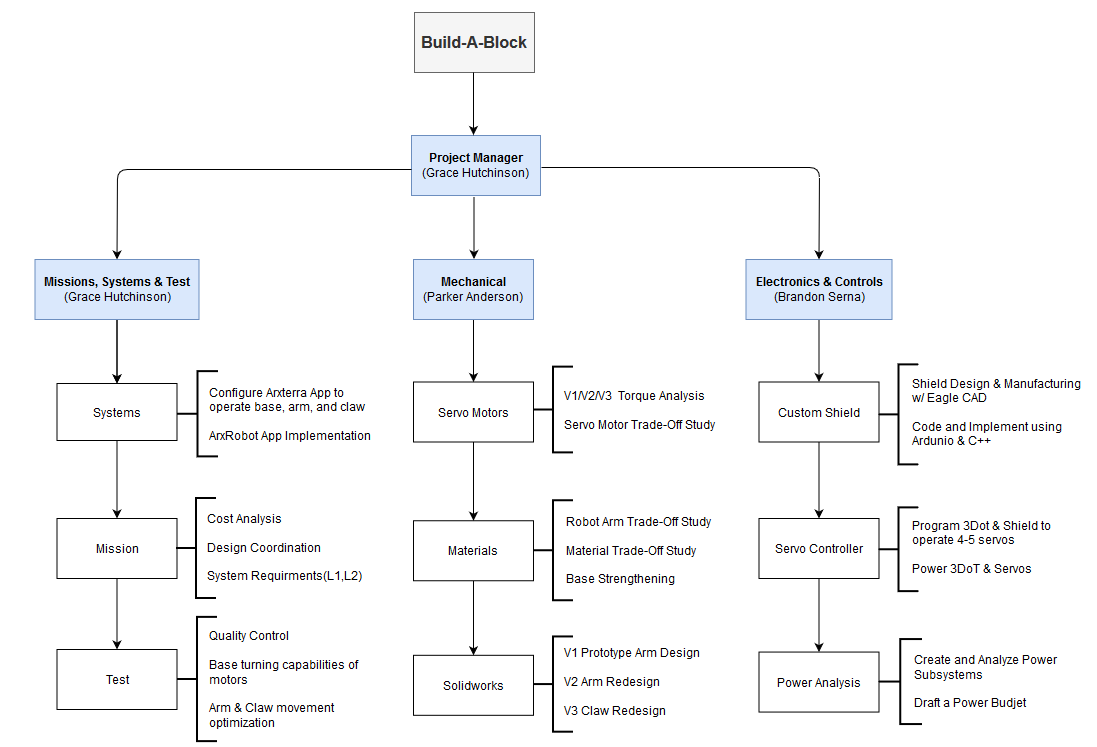
Figure 5. Build-A-Block Work Breakdown Structure
Product Breakdown Structure
The Build-A-Block Product Breakdown Structure (PBS) shows the robot milestones and work shared by group members and is divided into Missions, Systems & Test, Mechanical, and Electronics & Controls.
The MST will ensure user app interface control by implementing maneuverability in each part of the robot (the base, arm, and claw). During testing they will calibrate each version to optimize movement and fulfill each of the system requirements. The blog posts for each of the trade-off studies will be updated throughout the research process along with the mission objectives/ profile, system requirements, and budget.
The Mechanical will cover the solidworks design of the arm and base attachment, and each of the 3D printed prototypes. They will redesign necessary components in the arm and claw for each version, in order to fulfill the system requirements.
The Electronics & Controls will produce the designed PCB shield to implement with the robot. The implementation will require using the 3Dot to power the servos and shield, thus a power budget and calculations must be produced.
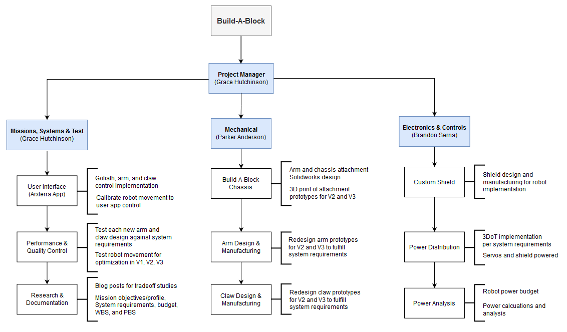
Figure 6. Build-A-Block Product Breakdown Structure
Cost
by: Grace Hutchinson
Here is an updated table all of items purchased and used in Build-A-Block. It includes test components that may not have been used in the final design, but used in previous versions and prototypes.
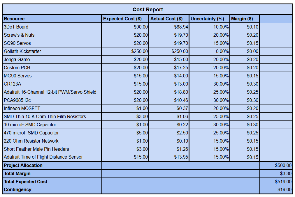
Figure 7. Cost report for Build-A-Block Project
Schedule
by: Grace Hutchinson
The Build-A-Block schedule highlights the time sensitive milestones we much reach during each period leading up to V1, V2, and V3. The red arrow represents the “critical path” that the team must follow to ensure productivity. The critical path emphasizes the design and redesign of the arm for each of the V1, V2, and V3 demos along with torque calculations, as well as the PCB design and implementation with the 3DoT.
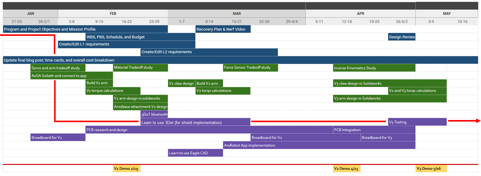
Figure 8. Build-A-Block Schedule
Burndown and/or Percent Complete
by: Grace Hutchinson
The Build-A-Block Burndown lists each of the Schedule Objectives and shows when each was worked on and completed. The team remained relatively on schedule for main tasks, such as with the PCB design and arm/claw re-design. The exception was the unplanned research that took longer for tradeoff studies which led to multiple edits, as well as troubleshooting the firmware.
Concept and Preliminary Design
by: Parker Anderson
Build-A-Block is the 8th generation in a series of Goliath rovers. The team began by using the Fall 2019 MicroDozer as inspiration, and thus decided to take the Goliath and add an attachable arm and claw module. The implemented arm and claw allow the robot to grab and place Jenga blocks in user defined locations.
Literature Review
by: Parker Anderson
To begin our arm research, I started out by Googling robot arm design. I was amazed at how many open source websites people had uploaded their designs to. I was researching arm designs on Instructables and Thingiverse, and we ended up using a design from Instructables. After we got our design from Instructables we immediately got it laser cut for our rapid prototyping stage of the project. It was nice to step through this process because it let us gauge what we need to do for the future iterations of our design and project as a whole. I never knew about the concept and importance of rapid prototyping until I experienced it this semester. It really taught me a lot about how to start a project from having nothing. It really helps you get inspired and build off the first design.
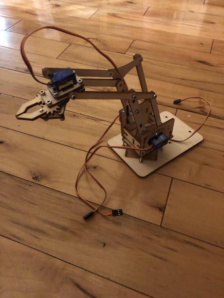
Figure 9. V1 laser-cut rapid prototype arm
After rapid prototyping, we realized we should analyze how much mass our servos could handle with respect to the base of our arm. We then derived equations for the torque that the arm would apply to the servo while the arm was holding a Jenga block. This is important because if the is to much force being applied to the arm it could break our servo. Our rapid prototype arm used SG90 servos with could handle our arm holding a Jenga block. This was a huge strength when it came to our rapid prototype. We then realized the weaknesses were the initial claw design and how short the arm was when compared to the reach it would need to access the top of a Jenga block.
Design Innovation
by: Parker Anderson
After our rapid prototyping we realized we would have to lengthen different parts of the arm and redesign the shape of our claw so it could not only reach the correct height of a Jenga block tower but hold the block in the correct fashion. I started this process by opening up our files from Instructables into Solidworks. This showed me my first problem. When the .dxf files were opened in Solidworks, Solidworks could not render them properly, giving weird surfaces and cuts in each part of the arm. It looked very hectic and I knew I could not easily resize these parts without remaking each part of the arm into a solid resizable piece. Once these parts were completely remade and made a new claw design, I was able to mate each part and actually make a virtual version of the arm that I could move around in Solidworks.
After I rebuilt and mated the parts I was able to model a simple rectangular cube the same size as a Jenga block tower so I could use that as a reference for how much I needed to resize the parts of the arm. After doing some calculations I increased the bicep and forearm 50 mm so the total reach of the arm would be at 270 mm. After this I exported each part as a .dxf file and AOSA was kind enough to again let us laser cut our arm.
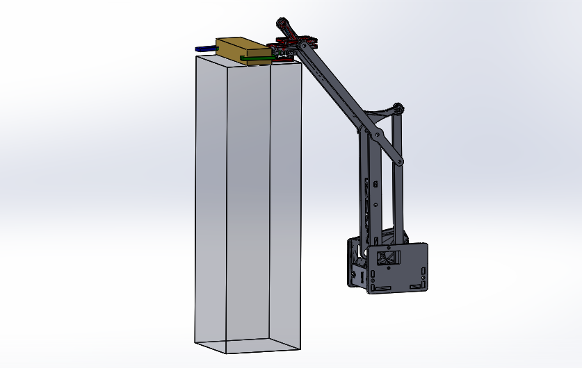
Figure 10. Build-A-Block virtual Solidworks design of V2 arm
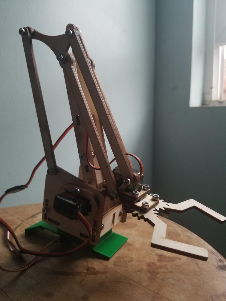
Figure 11. Build-A-Block laser cut V2 arm
Conceptual Design / Proposed Solution
by: Grace Hutchinson
The first System Block Diagram produced was created later in the process, thus it ended up being close to the final design. This design mainly consisted of the connections between the 3DoT board and custom PCB.
It required a user input using the ArxRobot application and this command then communicated with the 3DoT using the Bluetooth module. The 3Dot was used to power the chassis motors and connected directly to the custom PCB. The PCB was made to implement the Adafruit Servo Shield to control the 4 arm/claw servos and a force sensor to attach to the claw. Finally, a 5V battery supply was used to power the 4 servos.
This design was missing necessary details such as pin numbers and ground connections, however it allowed the group to produce a general plan for the PCB design.
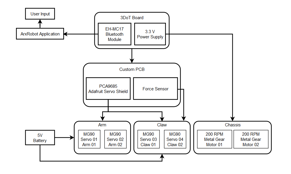
Figure 12. Preliminary Design Block Diagram
System Design / Final Design and Results
System Block Diagram
by: Brandon Serna
This section shows the final System Block Diagram, build off of the original preliminary design. The system begins with a user input through the ArxRobot application in order to communicate with the 3DoT board using the EH-MC17 Bluetooth module. The 3Dot board provides a 3.3 V logic supply that will power the 2 metal gear motors located in the Goliath chassis and the PCA9685 Servo Driver. The custom PCB Shield implements the Adafruit Servo Shield and a force sensor, but the intended distance sensor will not be used, as indicated by the yellow block. There will be 3 MG90S servos connected to the Adafruit Servo Shield, 2 for the arm and 1 for the claw. The shield has the ability to implement 4 servos as planned in the original design, however, due to being unable to print the final law design there will only be 3 servos in use. The servos will be powered by the 5 V external battery source consisting of 4 AA batteries connected in series.
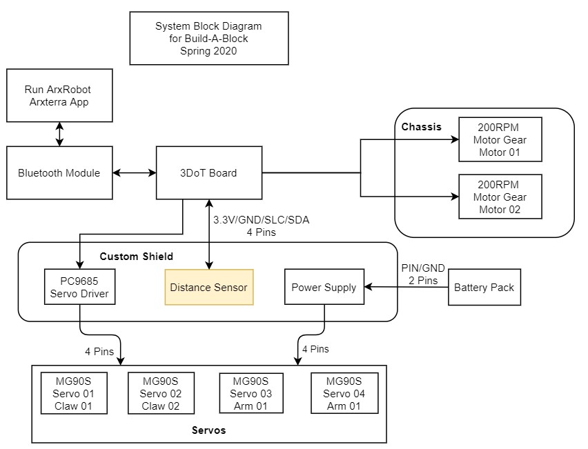
Figure 13. Build-A-Block System Diagram
Interface Definition
by: Brandon Serna
The following interface matrix shows the pin assignments for the 3DoT board, the PCA9685 Servo Driver, and the VL53L0X Time of Flight Distance Sensor
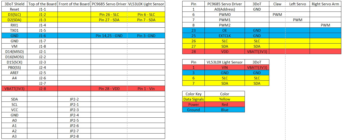
Figure 14. Build-A-Block Interface Matrix
Modeling/Experimental Results
by: Grace Hutchinson
Build-A-Block was designed using Solidworks, and the V2 and V3 iterations were used to adjust and tailor the design. Version 1 of the arm was created by rapid prototyping and overall, the arm was only created to test movement rather than fulfill any L1 Requirements. Once we assembled our arm, we went on to test the functionality of our arm through breadboard using an Arduino Uno and potentiometers to control the movement of the arm and claw, as described in the Build-A-Block PCB Design. When we realized that the claw would not be able to grip a Jenga block efficiently, nor would it be able to reach the top of the Jenga tower, we had to go back and redesign the arm length and claw, as described under Design Innovation. Version 2 of the arm required re-designing the arm to meet initial L1 requirements, this way the robot could eventually achieve the intended Mission Profile. Version 3 was meant to build on the V2 by improving upon design flaw where requirements were not met. Unfortunately, the V3 designs were not able to be implemented, however Solidworks allowed us to model these designs for future use.
With each version we tested the robot against the L1 Requirements before implementing changes. Below are the specific changes made between versions 1,2, and 3:
- Resizing the servo cut-outs due to switching from SG90 servos to slightly larger MG90servos
- Lengthening the arm to reach further and higher than a Jenga Tower
- Redesigning the claw to implement 2 servos and grip the Jenga Blocks lengthwise
With each adjustment there were tradeoff studies created, such as the inverse kinematics simulation with the changing arm length and torque calculations for the switching servos
Figure 15. V1 Arm and Claw Model

Figure 16. V1 Arm Built Prototype
Mission Command and Control
by: Brandon Serna
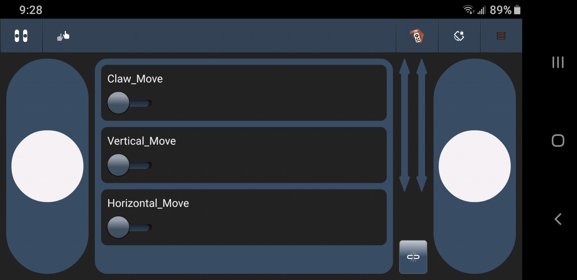
Figure 17. Widgets for Build-A-Block Control in Arx Robot app
Figure 17 shows the 3 custom widgets for the claw and arm moment. A detailed explanation of the commands and their implementation within the code is shown below.
MOVE (0x01) – Utilizes the existing tank slider controls provided by the ArxRoobot library to move the Goliath. We decided not to alter the existing move command due to the Goliath being more than capable of rotating in place efficiently.
Claw_Move(0x41) – This command controls the angle of the claw servo using a signed byte slider to dictate what angle between 0 and 90 degrees the claw should open or close to.
Vertical_Move(0x42) – Similar to the previous command, this command dictates the vertical position/movement of the arm. A signed byte slider dictates height at which the arm will be positioned
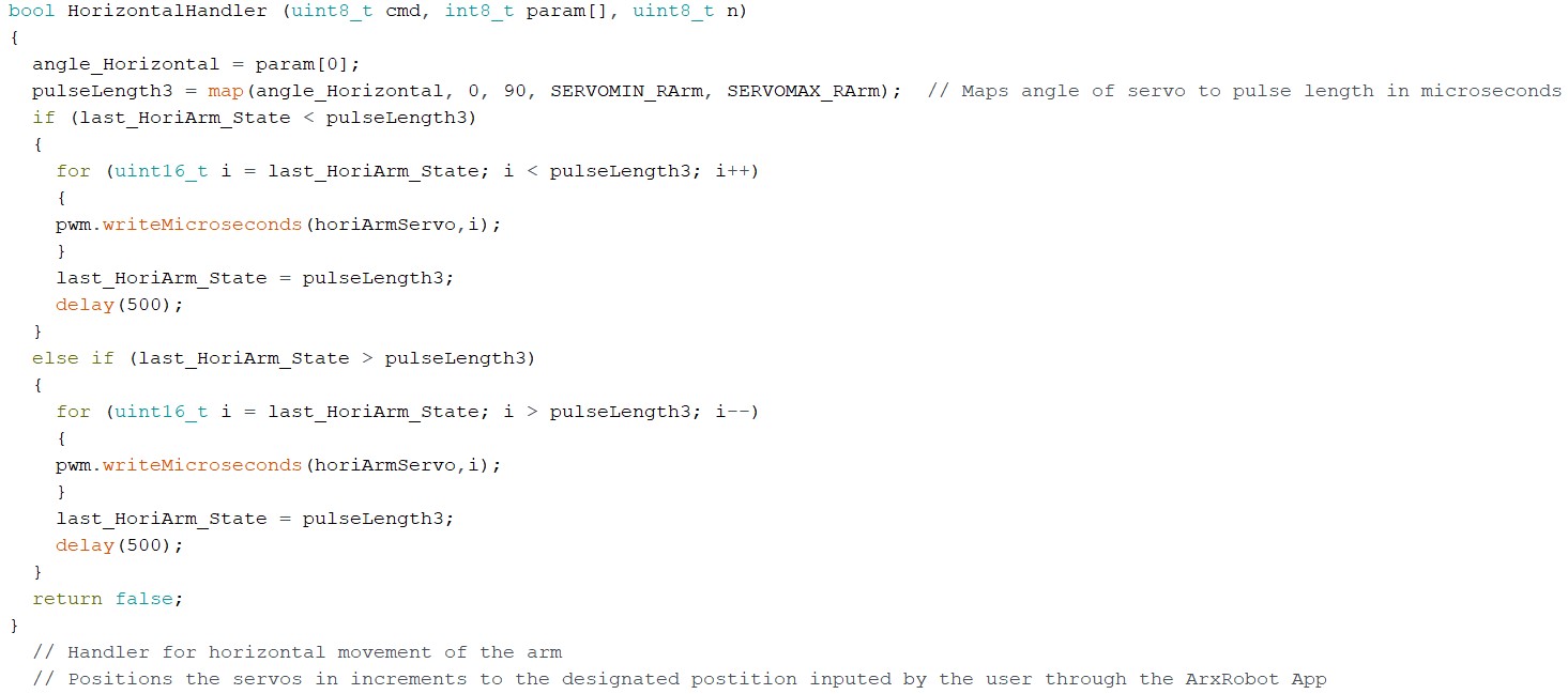
Horizontal_Move(0x43) – This command dictates the horizontal reach/potion of the arm, with 0 degrees being fully retracted and 90 degrees being fully extended. This command also uses a signed byte slider to indicate what degree the servo should be positioned at.
Electronic Design
PCB Design
by: Brandon Serna
Bread Boarding
For our V1 demo, we needed to both power and operate three SG90: One for the vertical movement, one for forward horizontal movement, and one for the claw. However, we were unsuccessful in providing consistent power using an Arduino UNO to all three servos simultaneously without the servos shaking. However, when powered individually, we were able to operate the robotic arm components successfully, which led us to the conclusion that we needed to use a separate power source aside from the 3DoT that was going to be used in our V2 and V3 demos later on.
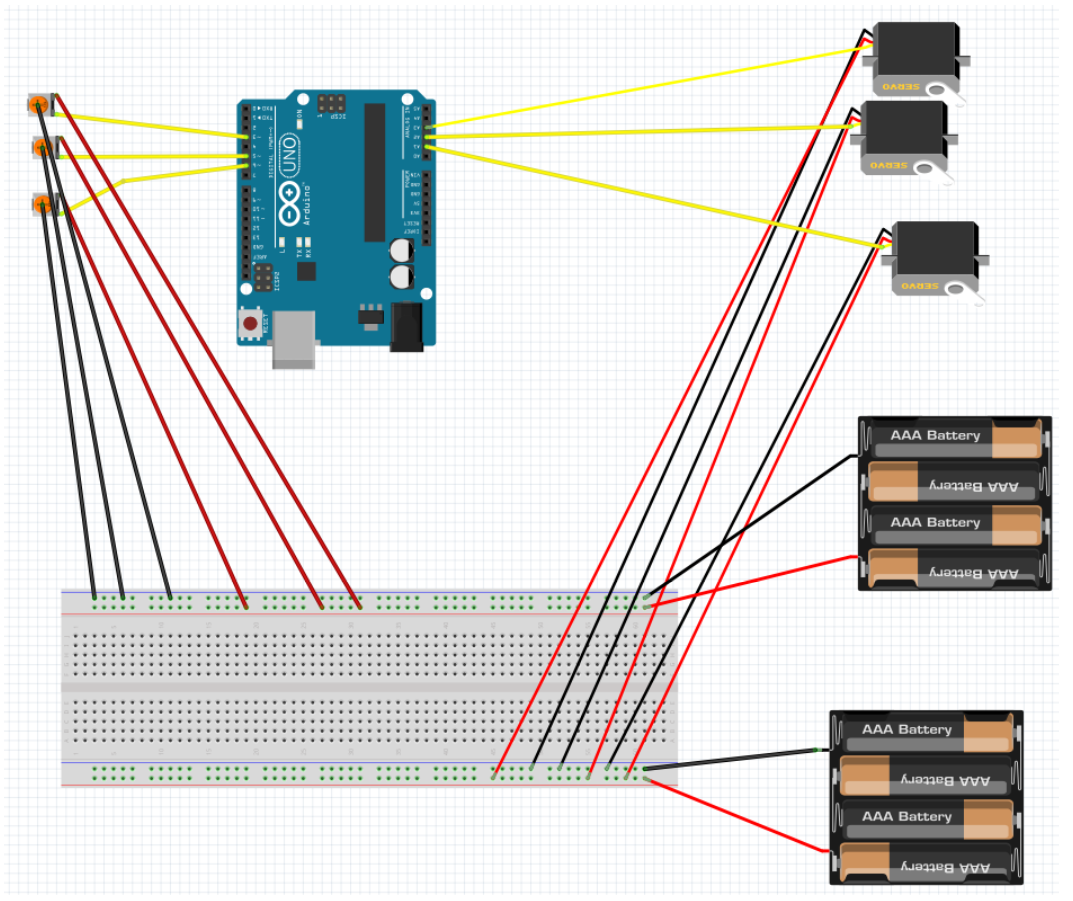
Figure 18. V1 Fritzing Diagram
EagleCAD PCB Design
Once we proved that our circuit functions properly, we set out to find a servo shield to base our PCB design off of. After researching a few Adafruit and Sparkfun servo shield, we decided to base our servo shield off of the Adafruit 16-channel PWM/Servo Shield because of it’s compatibility with the Arduino Lenoardo (which the 3DoT is based off of), it’s ability to utilize an external power source , and it’s ability to support and control up to 16 servos with the PCA9685 I2C.
The PCB needed to support up to 4 servos for the arm and claw functions, which ended up greatly simplifying the design by removing unnecessary IC components, such as servo pin headers and address pins. In addition, our PCB also needed to support the VL53L0X Time of Flight Distance Sensor, which were able to fit with ease pin wise due to the reduction in size of the PCD Design.
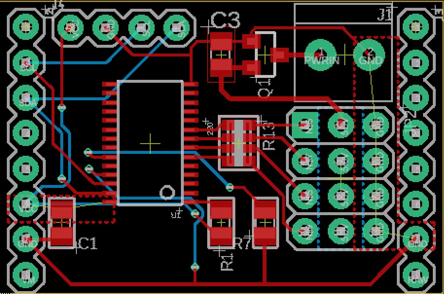
Figure 19. PCB Layout
Our PCB went through a few iterations, mainly dealing with fixes such as increasing the width of power and signal traces, adding power and ground planes, and including headers for the VL53L0X Time of Flight Distance Sensor. The final PCB Layout and Schmatic are shown in figures 11 and 12.
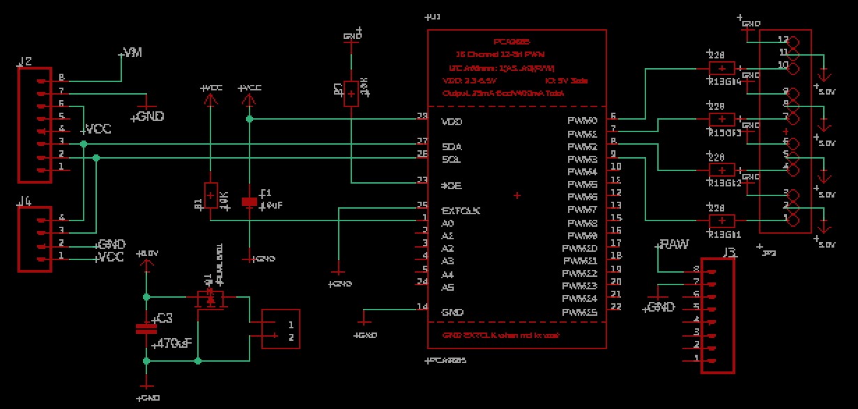
Figure 20. PCB Schematic
Print Results
Once the final schematic was complete, I had the PCB printed by JLC and proceed to solder the SMD parts to the board with the help of Jaap from AOSA. Although the process only took an hour, I ran into an issue regarding not having the right resistor array needed for the servos. Thankfully, Jaap was able to solve the problem by short circuiting the connections from the PCA9685 servo driver to the servos. Since we are only using one servo at a time, it is not necessary to have the resistor array serve as a protection against high current.
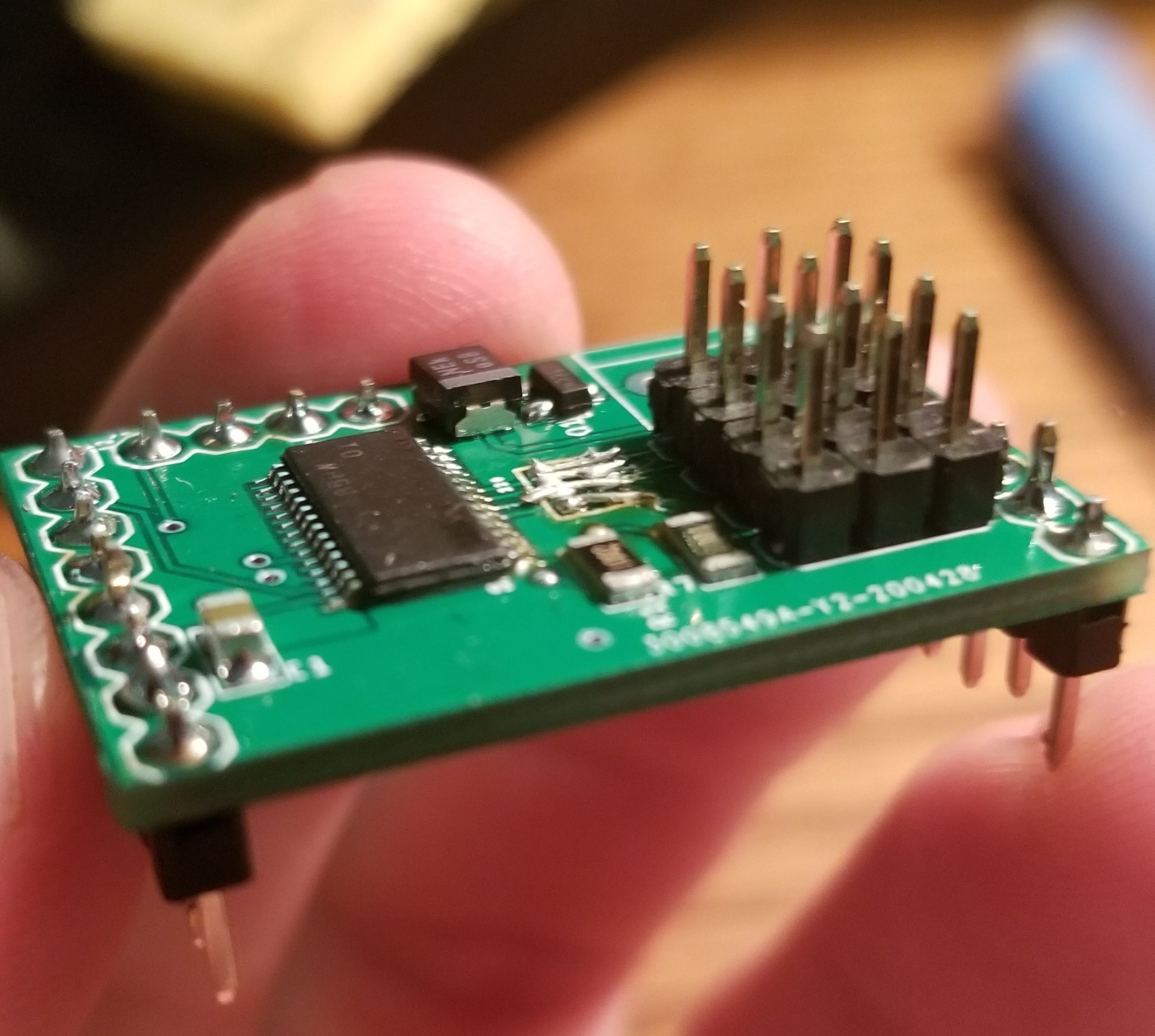
Figure 21. Printed PCB
Conclusion
Overall, despite our PCB not functioning, the PCB design and production proved to be a success. After having the SMD parts soldered using the free flow oven from AOSA, I was able to solder the pin headers with ease. Improvements can be made when applying the solder paste using the stencil and placing the SMD parts in their respective places as this was my first time doing so. The pin headers for the distance sensor was also soldered in the incorrect formation, but simply removing and resoldering the headers in the correct orientation is an easy process. Reasons for the PCB not functioning may stem from having to bypass the 220 Ohm resistor array, as I had purchased the wrong part. Although I did not have enough time to troubleshoot the voltages for the individual servos one by one, once tested for, however, the PCB could easily be fixed.
Firmware
by: Brandon Serna and Grace Hutchinson
Regarding the firmware for Build-A-Block the majority of time was spent trying to understand how the ArxRobot app communicates with 3DoT using custom command and telemetry packets, but once I was able to understand how custom commands work, it was just a matter of freshening up on my C++.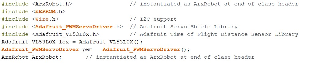
First, we included all the necessary libraries needed to run the Goliath, arm, and claw. The Adafruit PWM Servo Shield library simplified the code immensely due to using pulse width modulation in order to control the positions of the servos.
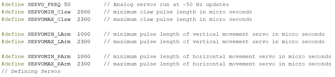
Next, we defined the servo angles and pulse length in degrees and microseconds, along with the minimum and maximum positions that the servos are able to travel. The pulse length values were determined based on the MG90S servo datasheet and were adjusted to meet the desired claw and arm positions through trial and error.
Next, we defined our 3 command handlers and their respective address according to the ArxRobot app.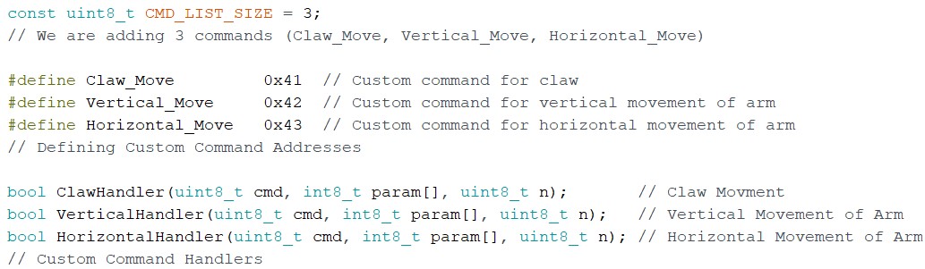
Each handler follows the same structure with the only difference being the minimum and maximum pulse lengths they are able to travel. For example, the Claw Handler receives an angle designated by the user in degrees varying from 0 to 90, which is then mapped to a minimum and maximum pulse lengths. We then check to see if the desired pulse length is greater than or less than the previous pulse length and use a for-loop to increment or decrement the previous pulse length to the desired pulse length.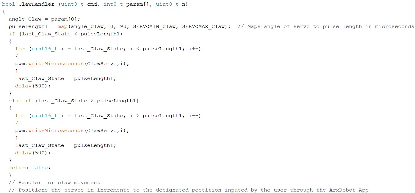
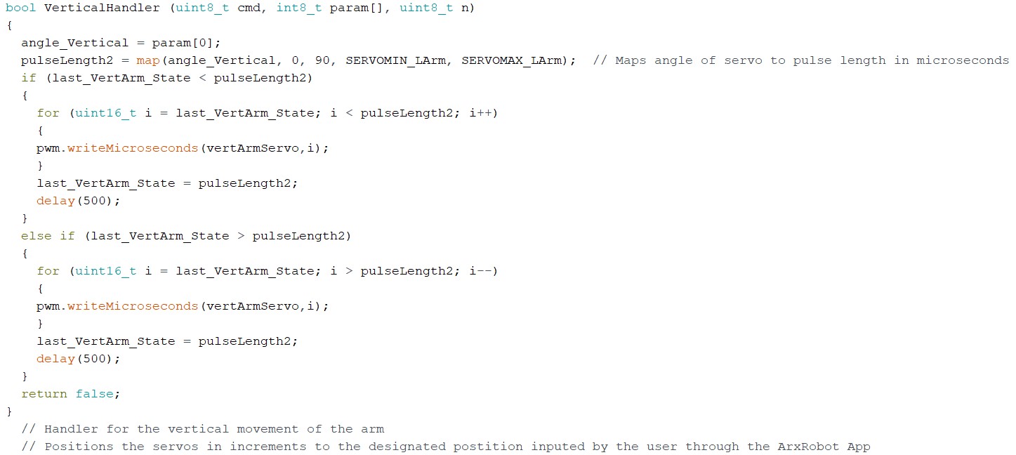
Finally, during the setup, we calibrate the arm and claw servos to their starting positions once we turn on the 3DoT.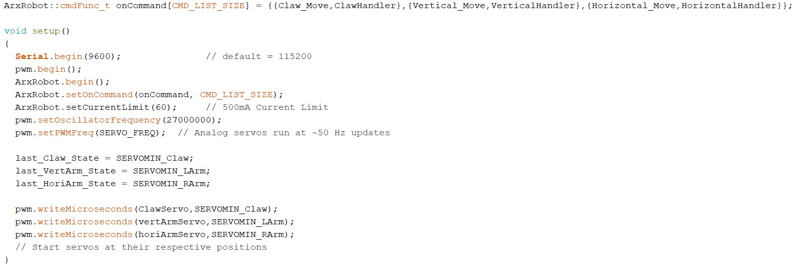
Although we were unable to implement the distance sensor and the inverse kinematic equations, I believe that the code we’ve generate will provide a sufficient starting point for the next iterations to build and improve upon in the future.
Mechanical/Hardware Design
by: Parker Anderson
After we were able to actually use and analyze how our V2 arm performed we realized we had to make more improvements. One thing that we noticed was using our inverse kinematics analysis of our V2 arm, we were wasting so much motion under our Goliath. We really only needed the claw to be able to reach onto the same surface our Goliath was moving on. We also wanted to be able to control each claw piece with its own independent servos. I first went into Solidworks and redesigned the claw attachment to include to servos to move each part of the claw independently. After this I ran into another problem. All of the mates I had from our V2 design got redefined by the new claw so the arm was not able to move correctly inside Solidworks. This would also mean that I could not redesign the length of the forearm to be shorter and the bicep to be longer.
I embarked on the mission of deleting every single mate and completely remating each part so the arm would correctly again, all these tasks took me weeks out of the semester to figure out how to do, but eventually I got the arm mated and everything was kind of working correctly. I still cannot figure out to this day why Solidworks would move the whole arm if I was only moving one of the claw pieces. I was still able to shorten the forearm and lengthen the bicep. Below is our final design animations of our arm.
Figure 22. V3 arm movement animation
Figure 23. Left claw movement animation
Figure 24. Right claw movement animation.
Verification & Validation Test Plan
by: Grace Hutchinson
The Verification Test Plan groups all L1 requirements into 4 Test Cases:
TC -01: Robot Motion
This TC is to ensure that the robot is working, and movement is sufficient before attempting the mission operation tests. This TC requires that the ArxRobot app can connect to the 3DoT on the robot and use the app interface to test necessary motion in the arm, claw, and base.
TC-02: Robot Visuals
This TC is to ensure that the robot has all necessary visual requirements, including the assemble and disassemble times. The specific visual requirements would include the laser cut arm, the 3D printed base, the custom servo shield, wiring, and the 3DoT.
TC-03: Robot Mission Ops
This TC ensure that the robot can fulfill the mission operation requirements. This means that the robot can stack blocks in a Jenga Tower structure, “push” and “pull” blocks to remove them from a Jenga Tower, and place blocks on top of a Jenga Tower.
TC-04: Robot Standards
This TC is to ensure that the robot meets general constraint requirements/ standards set on it by the class. This includes the overall completion date for demo, robot cost, mass, and power.
After the Test Cases were grouped and defined, the test environment and assumptions and predictions were specified. Procedure Steps were defined for each Test Case with Step Descriptions and Pass Criteria, and this allowed us to streamline demonstration.
Concluding Thoughts and Future Work
by: Parker Anderson, Brandon Serna, and Grace Hutchinson
Grace
This 8th generation of Goliath rovers was the first to implement a robotic arm and claw, thus the main focus was arm and claw design. The original design of the arm that was used for rapid prototyping used a single servo to open and close, and we later reshaped the claw to grip Jenga Blocks lengthwise with the ability to implement 2 servos. For future improvements, my recommendation would be to steer away from an open/close design and instead implement a clamp design where the servo causes the claw to slide open and closed.
Another recommendation would be to rapid prototype more and laser cut multiple arm and claw designs to test. The group was limited to two designs, but the sooner a design is physically tested the sooner the group can notice limitations in the design. The group conducted lots of research in the form of tradeoff studies and simulations, however the physical designs were our weak point, as we did not actively prioritize them.
My last recommendation would be to start working on the firmware and PCB right after the V1 rapid prototyping. The Build-A-Block code was repeatedly being updated, and each change also required debugging. The PCB required learning EagleCAD, and then multiple iterations of checking for issues and redesign. Overall, the tasks were completed, however there was less time for testing due to the PCB and firmware being completed later.
Brandon
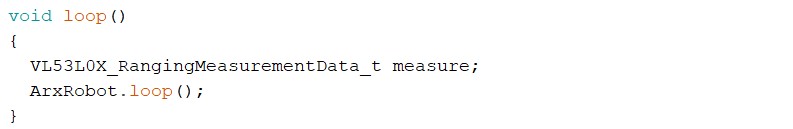
While our existing code is sufficient enough to operate the arm and claw remotely, it does not make use of the inverse kinematic equations and Vl53L0X distance sensor as we had intended to. The original goal was to use the inverse kinematic equations to allow the user to choose which block to pull/push off the tower. Then, as the arm would reach for a Jenga block, the distance sensor would dictate how far the arm would reach out before stopping to prevent the arm from accidently tipping the Jenga tower over and losing the game. Although we were unable to implement the VL53L0X distance sensor and the inverse kinematic equations into the code, I believe our existing code provides a excellent starting off point for future iterations to improve and build upon.
Parker
On the mechanical end of our project on improvement I would consider is making a peg that shoots out from in between the claw that could start the block removal process from the Jenga tower. Right now, the claw might not be strong enough to start that process. Another improvement I would make is on the claw. To my surprise the claw works pretty well already, but there might be another way to apply more force to the block so it could pull the block from the tower more efficiently. Another improvement I would make is using another material to make the arm out of. We were leaning pretty hard into acrylic. All in all, the arm is working much better than I thought it would, but there can always be improvements to any project.
References/Resources
by: Parker Anderson, Brandon Serna, and Grace Hutchinson