Advanced 3D Printer, The Conclusion
By Mustafa Alkhulaitit – Project Manager
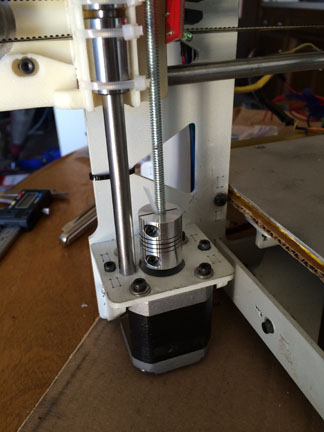
After 8 weeks of hard work, we have the 3D printer at 90% completion. During the last week, there were many complications and issues that prevented us from completing the printer to a 100%. The main reason for the delays was the printed parts provided by our mentor Mike Plume. The y-carriage, for example, had way too short rods that made calibration quite a hassle. We had to purchase extra stepper-motor couplers in order to try to calibrate the printer. Another issue was with the Bowden extruder holder. When we tried to calibrate it, we discovered that it was too short. Another issue was one stepper-motor that suddenly stopped working; this stepper-motor was supposed to be for the new extruder that is responsible for the filament. The stepper-motor needs to be replaced in order to dual print, which we did not have any time to fix or get new stepper motor.
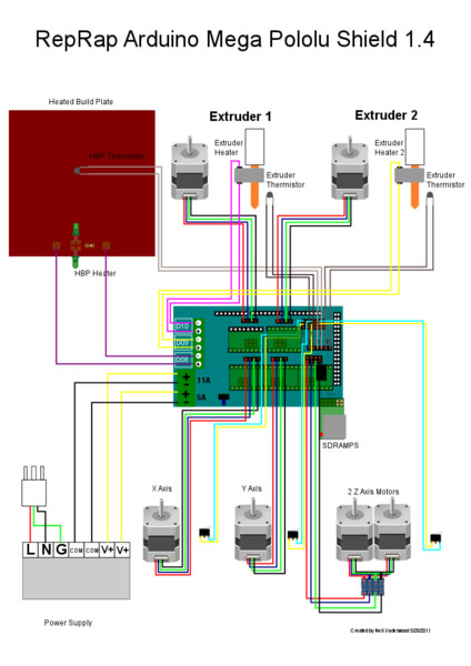
The endstops were also troublesome because the new frame is totally different than the previous one. We had to come up with quick solutions to put those on the new frame. Luckily, we no longer need the z-axis endstop because now we have auto leveling that is replacing the z-axis endstop. Another issue that we did not expect was replacing the Arduino MEGA 1280 to MEGA 2560. The MEGA 1280 works fine, but it unfortunately does not have enough memory to support dual printing. Since the firmware must be changed to adopt the new upgrades and changes, the MEGA 1280 couldn’t support those new changes. After getting the MEGA 2560, we were able to successfully upload the new firmware.
The following table shows what must be done on the printer to have it completely ready.
|
Type |
Issue |
Suggested Fix |
|
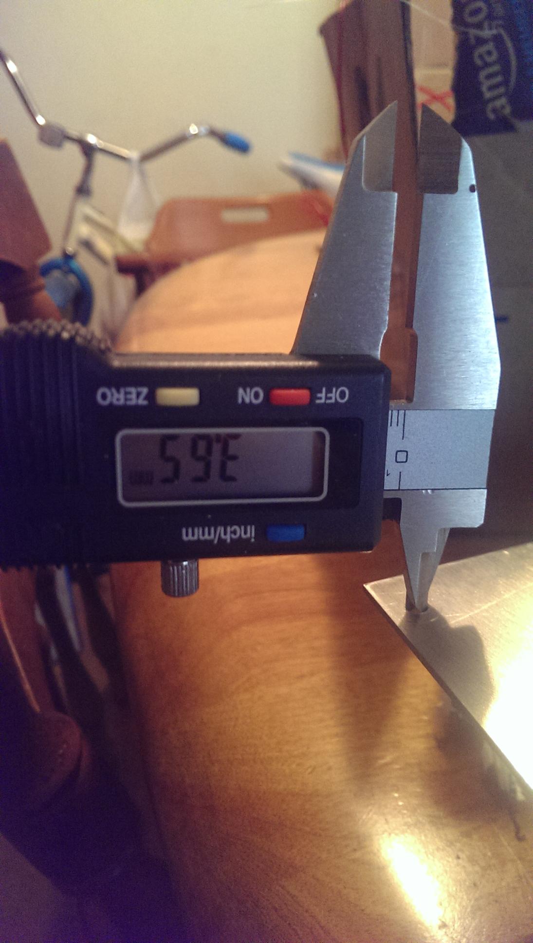
Y-Axis Rods |
4 mm radius– too small |
Replace with 5mm |
|
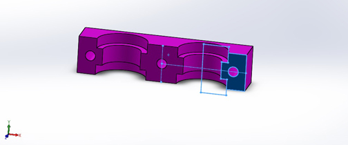
Y-Axis Carriage |
Bad print – starts breaking off |
Redesign and reprint |
|
E1 Stepper-Motor |
Does not turn – dead |
New NEMA 17 stepper motor |
|
Arduino cooling fan |
No pins available |
Find a way to connect to the RAMPS, or use external power supply |
|
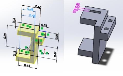
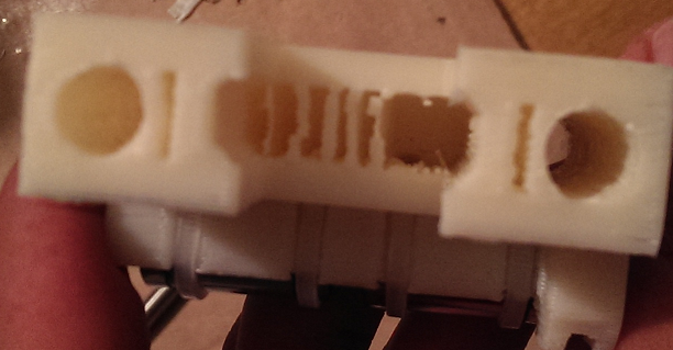
Nozzles holder |
Bad print – not aligned |
Redesign and reprint |
Most of the hard work has been already accomplished; the next project team should be able to finish the remaining tasks easily. Overall, our group has done a good job on this project, especially when considering that we received the printer really late (week 7). This project was not an easy one; the amount of precision and time needed make a very hard project to finish. The following are the tasks that our team has done:
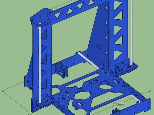
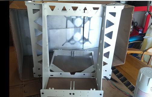
- Frame – was one of the toughest tasks. It required so much time and effort in order to put everything together.
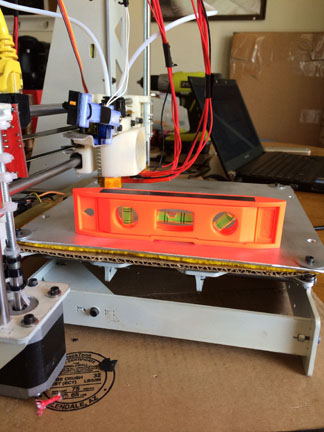
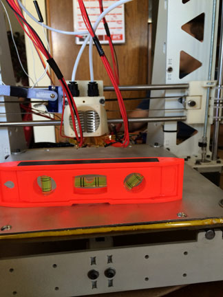
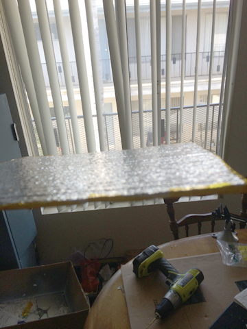
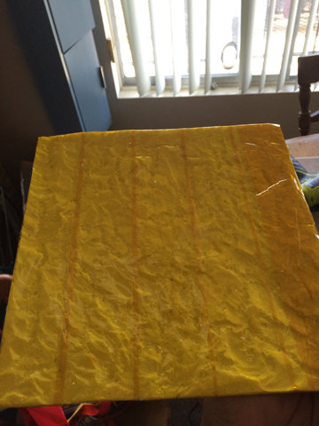
- Heat Bed – improved the isolation material and improved the appearance of the bed. Better appearance and improved performance. We also added bigger screw holes, considering thermal expansion and also added three-point leveling.
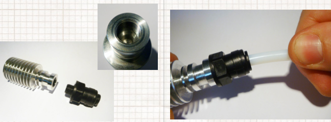
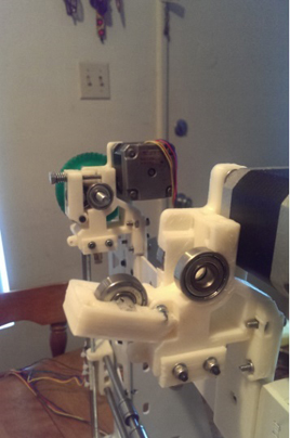
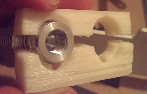
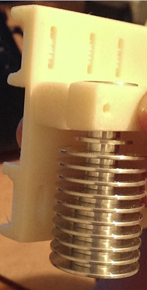
- Bowden Extruders – almost ready to use with the replacement of the defected stepper motor.
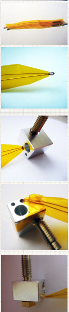
- E3D Hotends – ready to use and were tested to verify function. High quality and professional look.
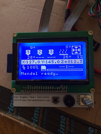
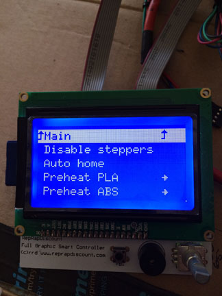
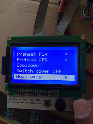
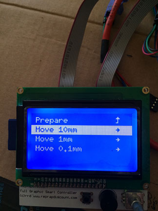
- LCD Controller – very nice feature with many options as can be seen in the photos below. It was tested and verified to function. Printer is now fully functional without a PC.
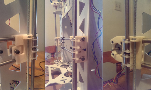
- Endstops – new position acquired. Verified to perfectly work.
- Auto Leveling – the best feature we have added to the printer. It works perfectly and saves time required to setup for printing.
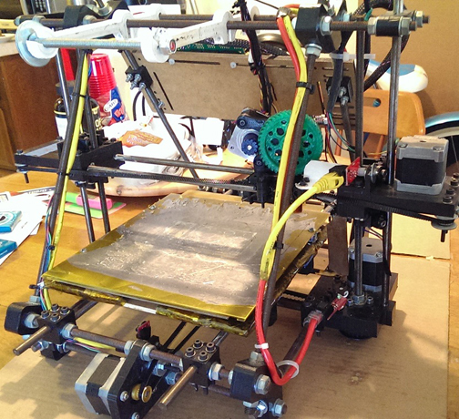
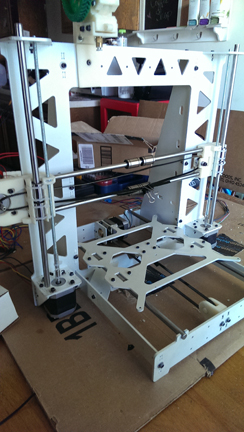
The following photos are a glance of the overall work done on the printer.