Spring 2016 3D SMD: Geared Stepper Motor Trade-Off Study

By Bao Loc Doan (Project Manager)

Requirement L2 – 3: Makeblock XY Plotter motors shall be modified to 0.05 mm error tolerance.

Table of Contents

Introduction

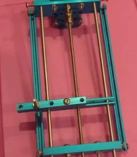
The Makeblock XY Plotter came with two (2) Makeblock 42BYG stepper motors. The stepper motors control our x-axis and y-axis movements. Geared stepper motors were given as a suggestion to replace our current x and y axis stepper motors for higher accuracy. After testing the current stepper motors and presenting our PDR demo, it was agreed that the movement of the x-axis and y-axis are too slow.

Discussion

Screen Shot 2016-04-01 at 6.46.19 PM

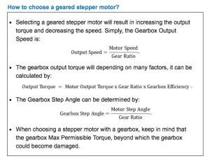
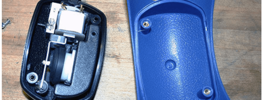
Figure 1 – Determining geared stepper motors (reference link at the end)

Our current stepper motor are bipolar stepper motors. Normally, these give more torque at low RPMs, while unipolar stepper motors spins faster for the same motor and power supply. The Makeblock Robot Plotter kit came with bipolar stepper motors as well as compatible stepper drivers.

We understand that what we are looking for are top output speed and the acceleration. Purchasing a 5:1 gearbox for the same stepper motor would change the step angle going from 1.8 degrees to 0.35 degrees if using the same stepper motor specs. After research, there is a Makeblock 5:1 geared 47BYG stepper motor that costs 59.99 per unit. This would make our machine increase accuracy by a factor of 5 but is out of our budget and would make our machine slower if we still microstep 1/16th. After obtaining the geared stepper motor, experiments will be conducted to determine if it’s possible to microstep the motors to 1/8th step and maintain desirable error specs.

We know that our Makeblock 42BYG motor does 200 steps/rev and since the driver is microstepping 1/16th, that means it can go 3200 steps per revolution. We could full step the motors, but we would lose accuracy, which is not wanted. The reason why full stepping the motor would make the machine lose accuracy is due to the possibility of the motor skipping a step or losing a step since each step is more distant. 

We would like to use the same mechanical parts as we do right now due to compatibility. If introduced to a different motor that may need a different voltage or current, then a different stepper driver would need to be developed in order to step the unit faster and thus spending more resources. Our current stepper motor is rated at 1.7 amps/phase, so in order to properly utilize the current stepper driver, the new motor must be rated at 1.7 amps/phase as well. We would need a motor that can run at least 5 times the motor speed of our current 42BYG, be driven by 1.7 amps/phase, rated 12 volts, and be priced under 35 dollars each (to fit in the budget) to maintain the same speed but have more accuracy.

A stepper motor driver that can step the motor higher could be a fix but our budget is very limited.

Conclusion

A 5:1 geared Makeblock 42BYG stepper motor will work in increasing our accuracy so our device could meet requirement L2 -3 – Makeblock XY Plotter motors shall be modified to 0.05 mm error tolerance. It will satisfy all compatibility requirements  as well but budget remains an issue due to the 5:1 geared Makeblock 42BYG motor being $59.99 per unit. The issue in a geared stepper motor lies in that it will definitely make the Makeblock XY plotter move slower than it already is if we keep the microstep at 1/16th. We will conduct experiments where we can find a ratio between accuracy and speed (possibly 1/8th step) that will satisfy our error requirement as well as produce a satisfactory parts per hour speed. However, the speed requirement is not mandatory for this semester and this can be resolved by modifying the stepper driver in future semesters. We conclude that the stepper motor(s) linked above would be a sufficient fit for our needs.

References

Stepper Online: Motors & Electronics. Retrieved April 1, 2016, from http://www.omc-stepperonline.com/high-torque-gear-ratio-51-planetary-gearbox-nema-14-stepper-14hs201504spg5-p-294.html


Spring 2016 3D SMD: Z-Axis Rapid Prototype


By Henry Nguyen (Electronics and Control)

Table of Contents

Introduction

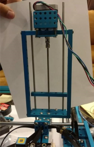
For our Z-Axis, we purchased a Thread Drive Pack from Makeblock which is able to move our thread drive beam up and down with great precision. This kit came with a DC Motor; however, for our uses, we found that using a stepper motor will be more convenient and easier to control with the current software we are using. By using a stepper motor, we are able to move our Z-Axis up and down with speed and precision. Our issue is attaching a stepper motor to our thread drive pack.

Implementation

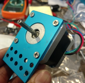
For our rapid prototyping, we will be using our X-Axis stepper motor, Me stepper driver, and our stepper motor bracket. I was able to utilize an extra bracket that came with our thread drive pack in order attach our Me stepper driver.

X-Axis Bracket

Figure 1. X-Axis Bracket

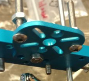
Extra Bracket

Figure 2. Extra Bracket

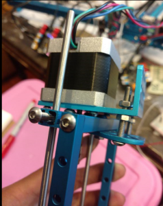
By connecting the extra bracket into our thread drive pack, I was able to utilize the two screws shown in Figure 2 to attach to our X-Axis bracket. The following image shows the stepper motor completely attached to our thread drive kit.

Angle 1 Installed

Figure 3. Installed Stepper Motor onto Z-Axis

Problems

When attaching the stepper motor shaft through the hole provided, I noticed that it was not completely straight. The shaft was slightly crooked due to the screws that are being attached to the brackets. This caused problems when running our stepper motor causing it to stall. By adjusting the nuts shown in Figure 3, I was able to straighten out the bracket so it became slightly more parallel to the surface.

Results

In order to test our stepper motor, we used the same code provided from our X-Axis stepper motors. We are able to use our X-axis because our stepper motor and me stepper driver came from our X-axis for this rapid prototyping. By inserting our Gcode values of X0 and X50, we were able to move at a measured distance of 0.3 inches. An example is shown in the Youtube video provided below.

https://www.youtube.com/watch?v=mQ80G-T7yP4                              

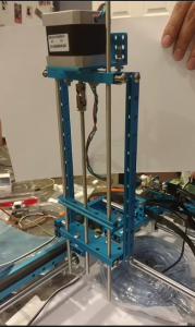
Zaxis Installed 1

Figure 4. Z-Axis Front View   

Z-Axis installed 2

Figure 5. Z-Axis Back View

Conclusion

Overall this rapid prototyping is a success. We are able to control our Z-axis thread drive kit with a stepper motor with great speed and precision all whilst being compatible with our current software. It is very easy to manipulate the distance our thread beam can move by inputting various Gcode values. I used X0 and X50 because it was able to move our 0.3 inches. Our reel feeder height is 0.17 inches. By moving 0.3 inches, it will be able to clear our reel feeder with extra space to spare. More testing will need to be done to see exactly the distance needed for our Z-axis to clear any obstacles. We will be using the shortest distance possible to increase our speed. This rapid prototyping also allowed me to visualize the design of the bracket that we will be creating in order to better fit a stepper motor onto our thread drive kit.

Spring 2016 3D SMD: Solenoid Valve Trade-Off Study

By Henry Nguyen ( Electronics and Control)

To satisfy requirement L2-7B:

A solenoid valve for vacuum system shall keep a stable temperature under 160° F during operation.  

Table of Contents

Introduction

In order for our machine to be able to pick and place components, we will use a solenoid to restrict the airflow from our vacuum pump when our machine is placing components. We are to test the limits of our solenoid valve in order to see if it is suited for our 3D pick and place machine. A factor to consider is that our plastic tubing can only withstand 160° F or 71° C.

—Equipment and Materials

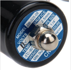
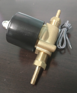
  1. 12V solenoid valve

Screen Shot 2016-03-27 at 8.33.21 AM

Figure 1. 12V Solenoid Valve


Datasheet Price Pipe Size Orifice Temperature Operation Pressure Dimensions Weight
Datasheet $10.99 1 / 4” 2.5mm -5 – 80 degree Celsius Min. 0kg/cm^2 –

MAX 10kg/cm^2

3.1 x 2.1 x 2 inches 10.4 oz


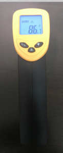
  1. Non-contact infrared thermometer

Screen Shot 2016-03-27 at 8.33.10 AM

Figure 2. Thermometer

  1. 12V DC power supply (obtained from ET-113)

Procedure

  1. We will be connecting our 12V DC power supply to our solenoid valve in order for our solenoid valve to be kept in the open position.
  2. We shall allow our solenoid valve to be on for 75 minutes and check the temperature of our solenoid valve consistently.
  3. We will also be constantly turning on and off our power supply in order to switch our solenoid valve off an on.

Results

After 75 minutes of run time, we were able to measure the temperature of our solenoid valve. Based on the following data, we were able to conclude that our solenoid valve will heat up rapidly to approximately 82° Celsius but will not heat up more than this. The rated temperature for our solenoid valve is -5°  – 80° C. When running our tests, we found that our solenoid valve heated up more than 80° C.


0 minutes 10 minutes 20 minutes 30 minutes 40 minutes 50 minutes 60 minutes 75 minutes
25° C 55° C 70° C 75° C 80° C 82° C 81° C 82° C


Table 1. Temperature of 12V Solenoid valve over time.

Conclusion

We have decided to return this solenoid valve because it is not suited for our 3D pick and place SMD machine. Since the solenoid valve heats up more than our maximum temperature of 71° C of our plastic tubing, it will not be ideal to use this solenoid. It is possible that our plastic tubing may melt onto our solenoid valve if it heats up pass 71° C.

Reference

Solenoid Valve Image:

DC 12V 1/4 Inch Electric Solenoid Valve for Air Water. (n.d.). Retrieved March 02, 2016, from http://www.amazon.com/dp/B00KKIH1YK/ref=sr_ph_1?ie=UTF8

Spring 2016 3D SMD: Conversion of EAGLE file to GCode: Initial Process

By Christine Vu (Missions, Systems, and Test) and Henry Nguyen (Electronics and Control)

A preliminary simulation was conducted to determine how to convert a PCB design on EAGLE to a Gcode/CNC file for the Makeblock X-Y Plotter Robot Kit to operate. We set up an assembly line to provide an understanding on how the Makeblock X-Y Plotter Robot Kit has potential to pick up a component and place a component down. Future works depend on the development of the project. If time is available, software will be updated.

Fig. 1

Fig. 1. Preliminary process of converting an EAGLE file to a GCode file.

Downloads:


Table of Contents

Eagle Schematic & AutoCAD DXF File

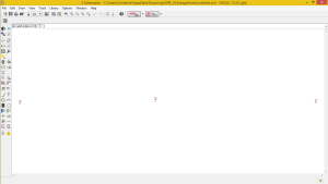
We began the process of the EAGLE conversion with a PCB design. Screenshots of the process are shown below.

  1. Add 3 SMT capacitors size 0805 on the PCB (Or use any design)
  2. Go to File -> Switch to board
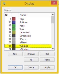
  3. Go to View -> Layer settings…
  4. Under Display -> Click None button -> Select Nr 23 tOrigins. This layer presents the origin of each component placed on the board
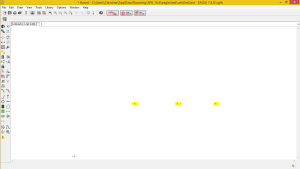
  5. Click Apply -> Click OK. The origins of the each component should only be show
  6. Go to File -> Export ->DXF

Schematic

Fig. 2. A set of three 0805 capacitors placed on the EAGLE schematic.

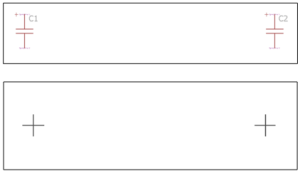
tOriginstOriginsBoard

Fig. 3. Display window of the EAGLE board. tOrigins was selected to show the origin of the capacitor (capacitor was placed on the top layer, t). Highlighted on the EAGLE board are the origins of each capacitor.

CNC File

aceConverter Download Link: http://www.dakeng.com/ace.htm

The Makeblock X-Y Plotter Robot Kit operates using Computer Numerical Control (CNC) files, which are often used with milling machines using G-code as the machine programming language. G-code are simply coordinates for a machine to navigate and trace. More information on understanding the G-code can be found here: http://www.tormach.com/machine_codes_gcodes.html

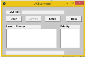
The DXF File exported by the EAGLE board was converted using a free open source application known as the aceConverter.

  1. Open aceConverter
  2. Click Open
  3. Select DXF File
  4. Click Convert

CNC File Macro

The control of the software was simplified with the implementation of a macro on Notepad++.

Information on how to run a basic macro is shown here: https://www.youtube.com/watch?v=Ks2u4MTTQbo

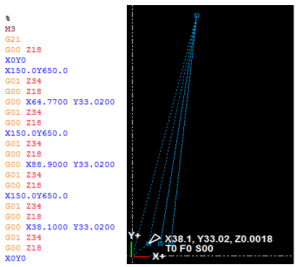
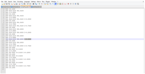
For our purposes, we set the macro to replace all Z-values with values to lift up (Z 18.0) and lift down (Z 34.0). After saving, this file, simulation was done to determine the placement of the reel feeders.

X-Y Plotter Simulation: NC Plot

An important aspect of the engineering method is the use of rapid prototyping and simulation. Before uploading GCode to the Makeblock X-Y Plotter Robot Kit to operate, a program was used to simulate the movement.

Gcode and NCPLOT

Fig. 4. Simulation of X-Y Plotter movement using NCPlot Program.

After using the macro in order to adjust all of our z-axis Gcode, we used a new software called NCPlot. This software is able to take .DXF and .Gcode files and simulate the actions of our X-Y plotter. I was also able to placed the reel feeder location X150.0 Y650.0 on the NCPlot editor directly. After finding the position of our reel feeder components, I was able adjust the Gcode to go to our reel feeders, pick up the component, head to the location of our first capacitor, and drop the component. This action was repeated for every component for our PCB. This program has great simulation features that allows us to visually see what our Gcode is doing. After verifying the simulation, we were able to send this file directly to our GRemote GUI and have our machine perform as expected.

Spring 2016 3D SMD: Preliminary Design Review

By: Bao Loc Doan (Project Manager)

Christine Vu (Systems Engineer)

Henry Nguyen (Electronics Engineer)

Nasser Alsharafi (Manufacturing)

Table of Contents

Program Objectives/Mission Profile

by Bao Loc Doan (Project Manager)

Program Objective Statement

When humans manually pick up and place down surface mount components onto a printed circuit board (PCB), there are problems with human accuracy and time efficiency. A pick and place surface mount device (SMD) is an automated device that can populate a PCB with surface mount components (resistors, capacitors, and IC chips) by referencing an EAGLE PCB file through the use of software. The pick and place SMD machine will be able to pick up the surface mount technology (SMT) components from 8 mm reel feeders and an integrated circuit (IC) tray and place the components down at the correct location until the board is finished. The customer has expressed the desire to create a pick and place SMD machine that can populate surface mount components as small as 0402 on all EE400D boards of Spring 2016 with the same specifications as the Madell Corporation Model DP2006-2.  The customer has expressed the desire to keep the budget of the project below $650 and finished before the end of Spring 2016.

Mission Profile

Once an EAGLE PCB file provided by any project from EE400D up until Spring 2016 is uploaded, the pick and place SMD machine shall begin populating SMT components from four 8 mm reel feeders and one IC tray onto the PCB. The smallest SMT component that will be placed is component size 0402. The pick and place SMD machine will be modified from a Makeblock XY plotter and replicate the error specification of the Madell Corporation Model DP2006-2.

Requirements

Level 1 Program/Project Requirements

by Bao Loc Doan (Project Manager)

To satisfy our customer, a list of requirements that our end product needs to meet were created. These requirements will move the design forward and provide traceability to our program objectives and mission profile.

  1. The SMD pick and place machine shall pick up and place down all SMT components provided by any EE400D PCB up until the end of Spring 2016.
  2. The SMD pick and place machine shall be modified from an XY Plotter to have the same error specification of Madell Corporation Model DP2006-2  (n.d).
  3. Software for the SMD pick and place machine shall accept all EAGLE PCB files of EE400D projects up until Spring 2016.
  4. The SMD pick and place machine shall have four 8mm reel feeders and one IC tray.
  5. SMT component size 0402 shall be the smallest component that the pick and place SMD machine can pick up.
  6. Total cost of finished project must be under $650.
  7. Deadline to complete the pick and place SMD machine shall be before the end of Spring 2016.

Level 2 System/Subsystem Requirements

by Christine Vu (Systems Engineer)

Level 2 System and Level 2 Subsystem Requirements are listed below. The process of forming requirements is not only crucial to the overall design of the project but also difficult to form due to the customer’s needs and the nonlinearity of designing. Through many revisions, the level 2 requirements were officially determined. Because this project is new to the Arxterra blog, references were obtained through scholarly journal research and outside resources other than the Arxterra blog.

Source Material:

Arra, M. , Geiger, D. , Shangguan, D. , & Sjöberg, J. (2004). A study of smt assembly processes

for fine pitch csp packages. Soldering & Surface Mount Technology, 16(3), 16-21.

CadSoft Computer GmbH and CadSoft Inc. (2011). EAGLE Freeware. Retrieved from:

http://www.cadsoftusa.com/download-eagle/freeware/

Changzhou Douwei Electric Co. Ltd. (n.d.). 42BYG Stepping Motor. Datasheet.

Makeblock. (2014, June 9). XY Plotter 2.0 How it works? Retrieved from:

https://www.youtube.com/watch?v=gY0xMYrWBDg

Panasonic. (2014, Feb. 4). Precision Thick Film Chip Resistors. Datasheet.

Shenzhen Maker Works Technology Co., Ltd. (2013). X-Y Plotter Robot Kit. Retrieved from:

http://www.makeblock.cc/xy-plotter-robot-kit/

TCI Precision. (2005). Blanchard Grinding. Retrieved from: http://tciprecision.com/machine-ready-blanks/capabilities/Blanchard%20Grinding

Telecommunications Industry Association. (2001). TIA/EIA-568-B.1: Commercial Building

Telecommunications Cabling Standard.

VBsProjects. (2014, July 12). Homemade SMD Pick and Place Machine – complete cycle.

Retrieved from: https://www.youtube.com/watch?v=CRSLbo_8nTQ#t=7m34s

Notes on Requirements:

L2 – # – Level 2 System Requirements (i.e. L2 – 1)

L2 – #x – Level 2 Subsystem Requirements (i.e. L2 – 1a)


L1 – 1 The SMD pick and place machine shall pick up and place down all SMT components provided by any EE400D PCB up until the end of Spring 2016.
L2 – 2: Working area must be within 12.2”x15.35”(310mmx390mm) based on the Makeblock X-Y Plotter Robot Kit.
L2-1a Surface to hold PCB shall be smooth with dimensions tolerances to be ±.001″, parallelism to .001″, and flatness to .001″ (TCI Precision, 2005).
L2-1b PCBs laid out for assembly shall be on a surface at 0° with respect to the floor.
L2-1c All wires using RJ25 connectors shall have a minimum bend radius of 4x its diameter (Telecommunications Industry Association, 2001).
L2 – 3: Pick and place SMD machine shall self-correct all orientation of IC chips before placement.
L1 – 2 The SMD pick and place machine shall be modified from an XY Plotter to have the same error specification of Madell Corporation Model DP2006-2 (n.d).
L2 – 4: Makeblock XY Plotter motors shall be modified to a maximum of 0.05 mm error.
L2-4a Resolution of all axes motors shall be less than 1.8°/step.
L2-4b Z-axis motor shall move the vacuum system at 90° with respect to the floor.
L1 – 3: Software for the SMD pick and place machine shall accept all EAGLE PCB files of EE400D projects up until Spring 2016.
L2 – 5: Software shall translate all EagleCAD files from EE400D PCB’s to G-Code files.
L2-5a Software shall include all x-y-z coordinates for SMD pick and place machine to read.
L1 – 4: The SMD pick and place machine shall have four 8mm reel feeders and one IC tray.
L2 – 6: All SMT resistors and capacitors shall remain in cut-tape of the reel feeders until the vacuum nozzle is ready to pick up the component.
L2-6a All reel feeders shall be installed on the working area, 12.2”x15.35”(310mmx390mm).
L2-6b Bracket to hold cut-tape of the reel feeders shall be higher than 1.10 mm.
L2-6c All motors used to peel off cut-tape of reel feeders must rotate 360°.
L2 – 7: IC tray shall store all IC chips required for one PCB assembly.
L2-7a IC tray shall be installed within working area, 12.2”x15.35” (310mmx390mm).
L1 – 5: SMT component size 0402 shall be the smallest component that the pick and place SMD

machine can pick up.

L2 – 8: Vacuum system shall be able to pick up all SMT components as small as size 0402.
L2-8a Vacuum nozzle shall be smaller than 0.50 ± 0.05 mm.
L2-8b A solenoid valve for vacuum system shall keep a stable temperature under 160° F during operation.
L1 – 6: Total cost of finished project must be under $650.
L2 – 9: All receipts and invoices shall be recorded and stored to verify all purchases.
L1 – 7: Deadline to complete the pick and place SMD machine shall be before the end of Spring 2016.


Design Innovation

Creativity Presentation

System/Subsystem Design

Product Breakdown Structure

By Christine Vu (Systems Engineer) and Henry Nguyen (Electronics Engineer)
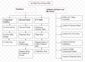
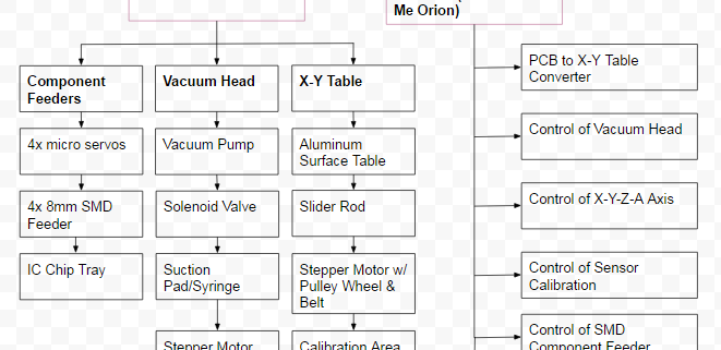
Product Breakdown Structure


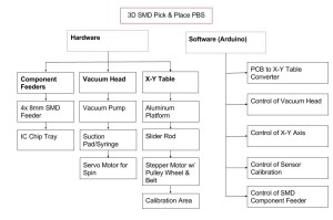
Figure 1. Product Breakdown Structure

The Product Breakdown Structure (PBS) shows all the functional blocks of our pick and place 3D SMD machine. The hardware is split into three different categories: Component Feeders, Vacuum Head, and X-Y Table. We will need a minimum of 4x micro servos to control our 4x 8mm reel feeders and an IC chip tray. The Vacuum head will consist of a vacuum to suction the components, a syringe or vacuum pen to pick up our components, a solenoid valve to block airflow and allow our components to be placed, and finally a stepper motor for rotation of the A axis. The X-Y Table is purchased from MakeBlock; however, we will need an aluminum surface table, slider rods, stepper motors, and calibration sensors to orientate our components. For software, we plan on using Arduino to program the Arduino Uno and Me Orion microcontrollers. Software must be able to convert Gerber files into G-code which can be read by our Me Orion microcontroller. We will need to be able to control all axis of our machine, the calibration sensor, component feeders, and solenoid valve through software.

Software Design

by Christine Vu (Systems Engineer)

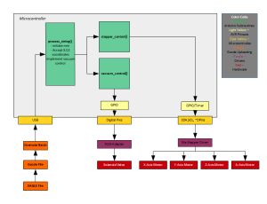
The Makeblock X-Y Plotter Robot Kit software begins with the submission of a gcode file. An EAGLE file is submitted and converted to gcode for the Arduino sketch to translate. There are three main subroutines to process the gcode coordinates–process_string, stepper_control, and vacuum_control. In process_string, the code searches for x-coordinates, y-coordinates, and z-coordinates. In the stepper_control, x-,y-, and z-coordinates, are processed to move the motors. The vacuum_control is used to detect when the vacuum tubing should open and close according to the change in the z-coordinates.

Preliminary Software Design

Figure 2. Software Design


Electronic System Design

Source Material

Me Orion:

Me Stepper Driver:

System Block Diagram

By Christine Vu (Systems Engineer) and Henry Nguyen (Electronics Engineer)

Screen Shot 2016-03-05 at 7.33.48 PM Screen Shot 2016-03-05 at 7.34.24 PM Screen Shot 2016-03-05 at 7.34.33 PM

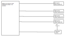
Figure 3. System Block Diagram

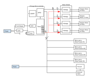
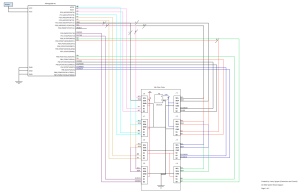
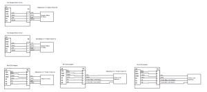
The images above is the system block diagram for our pick and place 3D SMD Machine. We are currently using a Me Orion microcontroller provided by Makeblock. This microcontroller has an Atmega3280-AU microprocessor, 8 Me RJ25 ports, two Me Stepper drivers, and 3 Me RJ25 adaptors. The pin outs for each Me RJ25 port is shown above which is connected to our microprocessor. Every port on our Me RJ25 has a SDA and SCL which is our I2C. This will be all connected to our PC4 and PC5 respectively. We will be using ports J1, J2, J3, J6 and J7. The first two ports is to control our X and Y axis stepper motors. J6 and J3 is to control our X and Y axis limit switches respectively. Finally J7 is to control our Z-axis micro servo. We plan on having another micro servo to serve as our A-axis component orientation which may connect to any other available ports. Next we are considering a Adafruit 16-Channel I2C interface in order to connect all of our micro servos for our reel feeders. We currently will need 4 servos for this purpose; however, for future semesters, they may need to implement more reel feeders. Our vacuum will be constantly running on a separate power source. The solenoid valve will close off the vacuum to prevent suction. This will allow our components to be placed onto our PCB after our machine picks it up.

Interface Definition
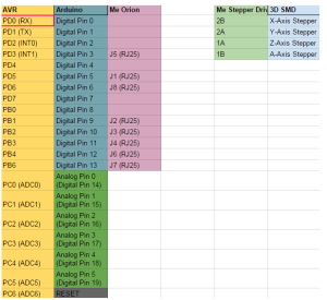
Interface Matrix

Figure 4. Interface Matrix

The image above is the interface matrix for our pick and place 3D SMD machine. We will be utilizing an Arduino Uno, Me Orion, and Me Stepper Driver. Me Orion and the Me Stepper Driver came with our X-Y Plotter. This Me Orion is based off of an Arduino Uno, which will allow us to code using Arduino, Scratch. and AduBlock. We will be using this microcontroller because it has 8 RJ25 ports which will be useful for all of our actuators. The Me Stepper Driver will be used to precisely control our stepper motors by operating our motors in full, half, quarter, eighth, and sixteenth step modes. This modes can be easily changed using the built-in DIP Switch. We will need 4 Me Stepper Drivers in order to control all of our stepper motors on each axis (x,y,z,A).
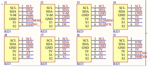
Me Orion Schematic

Figure 5. Me Orion Schematic

Me Stepper Driver Schematic

Figure 6. Me Stepper Driver Schematic

Specification for  Me Orion:

Operating Voltage: 6-12V DC power;

Microcontroller: ATmega238;

Detecting Angle: prefer at 30 degree angle;

Dimension: 80 x 60 x 18 mm (Length x Width x Height);

Specification for Me Stepper Driver:

  • Max current: ±1.35A
  • Max motor drive voltage: 25V    
  • Note: Me BaseBoard max supply  voltage 12V
  • Logic voltage: 5V
  • Dimensions: 48mm*24mm(Length × Width)

Mechanical Design

By Nasser Alsharafi (Manufacturing)

In this part of the project for the XY plotter I am coming up with the design of a Reel Feeder. The main purpose of a reel feeder is to feed the machine with the surface mounted parts. The reel feeder is made of aluminum. The main function of the Reel Feeder wheel is to roll and pass on the parts to the Reel Feeder base, which then the parts will be picked up by the vacuum.
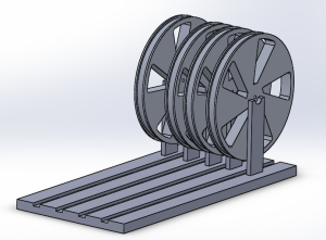
FeederReelAssembly

Figure 7. Complete reel feeder assembly 3D model
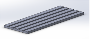
Reel Feeder Base

Figure 8. Reel feeder base

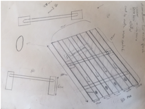
The base sheet of the reel feeder has four channels called the grooves in which the tape passes through. The base sheet of the reel feeder has a length of 270 mm and a width of 82 mm. Each of the grooves on the base sheet of the reel feeder has a width of 8 mm. The main function of the reel feeder is to guide the tape to the part of the feeder where the chip is first pulled and then picked by a vacuum pen. This action helps in preparation of the next chip. After, the chip is taken by the vacuum pen and is placed on the PBC board.
Reel Feeder Wheel

Figure 9. Reel feeder wheel

Initial Sketch of Reel Feeder Base

Figure 10. Drawing of initial reel feeder base

Currently, our reel feeder is manual, so there can be further improvements by making the reel feeder automatic. In order to make the reel feeder automatic, I have to design a mounting bracket for 4 micro-servos. Each channel has single micro-servo to pull back the tape while pushing the reel forward. This will be implemented by working with Henry Nguyen to control the micro-servos.   

Design and Unique Tasks

Design

by Nasser Alsharafi (Manufacturing)

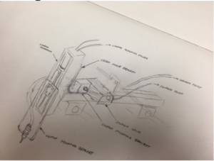
The pick and place vacuum nozzle system was sketched out. We had to take into consideration the weight of the entire system and make sure our actuator can support that weight.

Screen Shot 2016-03-05 at 7.14.25 PM

Figure 11. Actuator Design

Unique Tasks

By Bao Loc Doan (Project Manager), Henry Nguyen (Electronics Engineer), Christine Vu (Systems Engineer)

The stepper motor movement for the X and Y axis were mirrored. If we wanted the XY plotter to move left, it would move right. If we wanted the XY plotter to move up, it would move down. The solution was to change the connection of the wires to the opposite orientation. There are 4 wires that are output from the stepper motor. The wire colors are green, blue, red, and black. Rather than inputting it as green,blue,red,black into the connector, we switched the orientation to black, red, blue, and green. This changed the stepper motor orientation.

The limit switches also were not working correctly. When the XY plotter was supposed to stop due to it reaching the limits of its working area, the XY plotter kept going and ramming into the edges of the XY plotter. The manual for the XY plotter had the limit switches going from an RJ25 into port 5 of the Arduino. This was wrong. After hours of debugging and testing software, we realized this error. The limit switches ended up working after plugging it into port 7 of the Arduino.

Project Status

by Bao Loc Doan (Project Manager), Christine Vu (Systems Engineer), and Henry Nguyen (Electronics Engineer)

Currently, we were able to successfully translate an EAGLE PCB file to G-CODE. There are two layers, TORIGINS and TPLACE, specifically from EAGLE PCB that were used. TORIGINS displays the centerpoint of each component and TPLACE displays the outline of the component so the system could possibly recognize which orientation the component should be placed. The issue that we are currently facing is interpreting all the G-CODE location sets and translating it in a way for our XY plotter to properly read them.

Screen Shot 2016-03-05 at 6.27.23 PM

Figure 12. Torigins and Tplace layers

In order to successfully translate EAGLE to GCODE, the EAGLE file needs to be exported into a .DXF file. Then we can use ACEconverter to translate the .DXF file to GCODE. Using Notepad++, then the Z-axis can be modified to our needs.

Screen Shot 2016-03-05 at 6.27.33 PMScreen Shot 2016-03-05 at 6.27.43 PM

Figure 13. ACEconverter and Notepad++

A trade-off study on the vacuum system was conducted as well. We are currently deciding which aquarium pump to use, whether it is 20 gal, 40 gal, or 100 gal. There are still experiments that need to be conducted and we will provide updates when those experiments are done. The trade-off study blog was created and can be seen here.

A separate blog has already been made for the XY plotter that was purchased and that blog will explain all design ideas as well as provide updates on how the XY plotter functions. The blog can be seen here.

Work Breakdown Structure

By Bao Loc Doan (Project Manager) and Christine Vu (Systems Engineer)

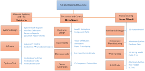
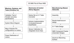
Our Work Breakdown Structure (WBS) was modeled after the Robot Project WBS. Each division will have tasks delegated to them and will be their primary responsibility to complete. As mentioned in 05 Preliminary Project Plan PDF, the WBS will be a “…  hierarchical tree structure where each node (group) is the responsibility of only one engineer.”  A completion of the WBS will indicate a successful project. The chart below will be the pick and place SMD machine WBS.

WBS

Figure 14. Work Breakdown Structure

Source Material

[1] G.Hill (2016, Feb). 05 Preliminary Project Plan [Online]. Available: 05 Preliminary Project Plan PDF

Project Schedule

A project schedule will lay out the deadlines that each engineer needs to conform to when assigned to their tasks. The schedule will allow the engineer to understand how much time they have left as well as the progression needed to complete the project. When deadlines are not met, there will be a chart illustrating the remaining cumulative work as well as baseline cumulative work.

Top Level Schedule

By Bao Loc Doan (Project Manager) and Christine Vu (Systems Engineer)

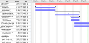
The top level schedule tasks were derived from our WBS. Each module in the WBS were taken into account. While working with the systems engineer, we developed a schedule that will divide all tasks in a progression that we believe will lead to project completion. Each required task will have a time estimate, and failure to meet the time estimated will result in the delay of every task assigned after. The chart below is the pick and place SMD top level schedule.

Screen Shot 2016-03-03 at 9.47.22 PM

Screen Shot 2016-03-03 at 9.47.56 PM

Figure 15. Top Level Schedule

System/Subsystem Level Tasks

By Henry Nguyen (Electronics Engineer), Christine Vu (Systems Engineer), and Nasser Alsharafi (Manufacturing)

Reference top level schedule for system/subsystem level tasks.

Burn Down and Project Percent Completion

by Bao Loc Doan (Project Manager)

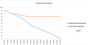
A burn down graph is a visual representation of the expected progression and remaining progression. The top level schedule was created in ProjectLibre, so we had to use Excel to create a burn down graph. The task burn down and the percent burn down will be shown below.

 Screen Shot 2016-02-26 at 10.03.38 AM Screen Shot 2016-02-26 at 10.04.30 AM

Figure 16. Burn Down Graphs

System Resource Reports

Mass Report

By Christine Vu (Systems Engineer)

Vacuum System Components Preliminary Mass (g) Uncertainty (%) Margin (±g) Expected Mass (g) Actual Mass (g)
Stepper Motor (A-Axis) 290.00 5% 14.5 304.50
Stepper Motor (Z-Axis) 290.00 5% 14.5 304.50
Solenoid Valve 99.79 5% 4.99 104.78
Makeblock Stepper Driver (2 ct.) 40.00 5% 2 42.00
Vacuum Syringe 68.00 5% 3.4 71.40
Vacuum Tubing (25-ft.) 68.00 5% 3.4 71.40
Project Allocation Trade-Off Study will be obtained
Total Expected Mass 898.58
Total Margin 42.7895
Total Actual Mass
Contingency

Table 1. Mass Report

Summary

The pick and place SMD machine will not need a power resource report because we are not limited in power. A waiver request will be submitted for approval.

The mass resource report is on the vacuum system to determine the mass. The stepper motor expected weight have been obtained from the Makeblock specifications on their X-Y Plotter Robot Kit (Shenzhen Maker Works Technology Co., Ltd., 2013).

The Makeblock Stepper Motor Driver is a component used to control the stepper motor with  the ArduinoUno. It contains a stepper driver chip, 4 wire bi-polar stepper motors, a potentiometer, DIP switch, and a heat sink.

Because the components have not been purchased, project allocation, actual mass, and contingency will be obtained after trade-off studies have been conducted.

Source Material:

Shenzhen Maker Works Technology Co., Ltd. (2013). Me Stepper Motor Driver. Retrieved from:http://www.makeblock.cc/me-stepper-motor-driver/

Project Cost Estimate

By Bao Loc Doan (Project Manager) and Christine Vu (Systems Engineer)

Resource Unit Price ($) Quantity Shipping Cost ($) Preliminary Cost ($) Uncertainty (%) Margin (±$) Expected Cost ($) Actual Cost ($)
MakeBlock XY Plotter Robot Kit $267.66 1 $0.00 $267.66 8.00% $21.41 $289.07 $267.66
Tetra Aquarium Pump $17.59 1 $0.00 $17.59 8.00% $1.41 $19.00
8 mm Reel Feeders (Holds 4) $32.00 1 $0.00 $32.00 8.00% $2.56 $34.56
Micro Servo $7.00 4 $0.00 $28.00 8.00% $2.24 $30.24
12V Solenoid Valve $10.00 1 $0.00 $10.00 8.00% $0.80 $10.80
Aluminum Surface & Machinist Labor $60.00 1 $0.00 $60.00 8.00% $4.80 $64.80
42BYG Geared Stepper Motor $60.00 2 $0.00 $120.00 8.00% $9.60 $129.60
Vacuum Tubing (25-ft) $5.00 1 $0.00 $5.00 8.00% $0.40 $5.40
MakeBlock Stepper Driver $18.00 1 $0.00 $18.00 8.00% $1.44 $19.44
Sensor Calibration $50.00 1 $0.00 $50.00 8.00% $4.00 $54.00
Connectors $2.00 2 $0.00 $4.00 8.00% $0.32 $4.32
$0.00 $0.00 8.00% $0.00 $0.00
Project Allocation $650.00
Total Expected Cost $612.25
Total Margin $48.98
Total Actual Cost $267.66
Contingency $86.73

Table 2. Cost Report

Summary

The cost report supports all parts needed so far to construct the pick and place SMD machine for Spring 2016.

The Makeblock XY Plotter is an XY plotter that can be easily modified to our needs. This specific XY plotter has a working area of 12” x 15” so it can easily fit our PCB fabrication requirements (4” x 3.2” as per free Eagle CAD board working area) and additional reel feeders. The Makeblock XY plotter ships all the parts as a kit and would be much more efficient to build since we would no longer need to design the entire XY plotter. The accuracy of this XY plotter needs to be increased by a factor of 2 (as requested by the customer) and a simple solution is to implement a geared stepper motor.

The Makeblock Gearbox Stepper Motor will be implemented into our pick and place SMD machine so our precision error meets customer standards of 0.002”.

The aquarium pump, solenoid valve, tubing, syringe, and connectors shall be used for the vacuum system in the pick and place SMD machine. The aquarium pump is easily modified to become a vacuum and the solenoid valve with brass fittings will control when the vacuum suctions in order to pick and up and place down the components as intended. The tubing, syringe, and connectors will connect each individual component to make the vacuum system.

All of our surface mount resistors and capacitors shall be placed in the 4x 8 mm reel feeders so they can be populated onto the PCB. After Spring 2016, 16x 8 mm reel feeders will be implemented into the pick and place SMD machine.

The aluminum surface will be the working area of the entire pick and place SMD machine. The machinist labor is included into the price. The Makeblock XY plotter will need to securely fit into the aluminum surface and there will also be an aluminum clamping system that needs to be drilled into the aluminum surface.

The Makeblock stepper motor driver will be used in conjunction with the Makeblock stepper motor to control our vacuum nozzle. In order for the vacuum to be able to pick up components, the ability to move in the Z-axis is required. We have plans to implement one Makeblock stepper motor on the z-axis and will need the circuitry required.

Spring 2016 3D SMD: Vacuum System Trade-Off Study

By Henry Nguyen ( Electronics and Control)

DISCLAIMER: We have not purchase our vacuum pump; however, we spoke to President Watts and he would like to see the procedure for this trade off study. This blog will be updated when we obtain our materials and perform our tests.

Introduction

In order to find a vacuum pump that best suits our pick and place SMD machine, we needed to compare several different options. Considering pressure and cost will be crucial for this trade off study. Our goal is to find a vacuum pump that is able to pick up surface mount components and IC chips. We found that we can modify a 60 -100 gallon Tetra Whisper Aquarium pump to act as a vacuum for the price of $17.59.

—Equipment and Materials

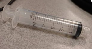
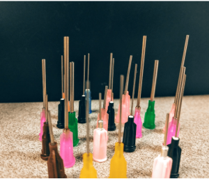
Syringe 5mL                      Needles-min

Figure 1. 5 mL Syringe                                                          Figure 2. Needle heads

  1. A 5mL syringe with a small needle with a diameter of less than 0.50mm

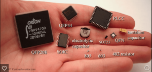
ICs-min

Figure 3. Various surface mount components and IC Chips

      2. Various surface mount components and IC Chips

Tetra 100 Gal-min

Figure 4. Tetra Aquarium Pump

      3. Vacuum pump (Modified aquarium pump) 

Tubing-min

Figure 5. Tubing

      4. 3/16” tubing

—Procedure

  1. We will modifying the following aquarium pump in order to turn it into a vacuum pump. The following link provides step-by-step details on how to modify our aquarium pump
    1. http://www.instructables.com/id/Circuit-Board-Lab-POV-Business-Card/step5/
  2. Tubing length will be cut to be as short as possible to allow maximum suction pressure. The size will be determined based on the design of our aluminum surface table. (Approximately 1.5 – 3 ft)
  3. A 5mL syringe will be used as our vacuum head and will be modified by connecting our tubing to the syringe and our vacuum
  4. After setting up our equipment, we will be testing whether or not our vacuum is able to pick up a 402 component.
  5. Next we will be testing the heaviest IC chip that we have access to in order to determine if our small needle is able to pick up the IC Chip.
  6. Our last step is to test how much mass our vacuum pump is able to pick up. In order to do so, we will have a small scale with an accuracy of 0.1 grams and we will place an object on that scale. We will use our vacuum to see how much grams is deducted of the total mass when attempting to pick up the object. The following video shows a demonstration of this process.
    1. http://www.exair.com/pages/theater.aspx?gi=13001&dlg=1&gf=Vacuum+Generators

—Results

  • Currently unavailable until we purchase our equipment

—Analysis/Discussion

  • Currently unavailable until we purchase our equipment

—Conclusions/Implications

  • Currently unavailable until we purchase our equipment

—References

Vacuum Pump modifcation and image:

Sponges, S. (n.d.). Build an SMD Vacuum Pick and Place Tool. Retrieved February 25, 2016, from http://www.instructables.com/id/Circuit-Board-Lab-POV-Business-Card/step5/

Vacuum Pump mass test:

EXAIR: Manufacturing compressed air products since 1983. (n.d.). Retrieved February 25, 2016, from http://www.exair.com/pages/theater.aspx?gi=13001

ICs Image:

Curious Inventor. (n.d.) Hand full of SMDs Labeled. Retrieved February 25, 2016, from

http://store.curiousinventor.com/media/smt/hand_full_of_smds_labeled.jpg

Tetra Whisper Aquarium Pump Image:

Tetra Whisper Air Pump (Non-UL). (n.d.). Retrieved February 26, 2016, from http://www.amazon.com/Tetra-77851-Whisper-Pump-10-Gallon/dp/B0009YJ4N6/ref=sr_1_1?s=pet-supplies

3/16” Tubing Image:

Python. (n.d.). Retrieved February 26, 2016, from http://www.amazon.com/Python-Airline-Tubing-Aquarium-25-Feet/dp/B000255NYQ/ref=pd_bia_nav_t_1?ie=UTF8

Spring 2016 3D SMD: Preliminary Project Plan

by Bao Loc Doan (Project Manager)

Christine Vu (Systems Engineer)

Henry Nguyen (Electronics Engineer)

Nasser Alsharafi (Manufacturing)


Table of Contents

Work Breakdown Structure

By Bao Loc Doan (Project Manager) and Christine Vu (Systems Engineer)

Our Work Breakdown Structure (WBS) was modeled after the Robot Project WBS. Each division will have tasks delegated to them and will be their primary responsibility to complete. As mentioned in 05 Preliminary Project Plan PDF, the WBS will be a “…  hierarchical tree structure where each node (group) is the responsibility of only one engineer.”  A completion of the WBS will indicate a successful project. The chart below will be the pick and place SMD machine WBS.

WBS

Figure 1. Work Breakdown Structure

Source Material

[1] G.Hill (2016, Feb). 05 Preliminary Project Plan [Online]. Available: 05 Preliminary Project Plan PDF

Project Schedule

A project schedule will lay out the deadlines that each engineer needs to conform to when assigned to their tasks. The schedule will allow the engineer to understand how much time they have left as well as the progression needed to complete the project. When deadlines are not met, there will be a chart illustrating the remaining cumulative work as well as baseline cumulative work.

Top Level Schedule

By Bao Loc Doan (Project Manager) and Christine Vu (Systems Engineer)

The top level schedule tasks were derived from our WBS. Each module in the WBS were taken into account. While working with the systems engineer, we developed a schedule that will divide all tasks in a progression that we believe will lead to project completion. Each required task will have a time estimate, and failure to meet the time estimated will result in the delay of every task assigned after. The chart below is the pick and place SMD top level schedule.

Top level schedule 1

Top level schedule 2

Figure 2. Top Level Schedule

System/Subsystem Level Tasks

By Bao Loc Doan (Project Manager), Henry Nguyen (Electronics Engineer), Christine Vu (Systems Engineer), and Nasser Alsharafi (Manufacturing)

Reference top level schedule for system/subsystem level tasks.

Burn Down and Project Percent Completion

by Bao Loc Doan (Project Manager)

A burn down graph is a visual representation of the expected progression and remaining progression. The top level schedule was created in ProjectLibre, so we had to use Excel to create a burn down graph. The task burn down and the percent burn down will be shown below.

 Screen Shot 2016-02-26 at 10.03.38 AM Screen Shot 2016-02-26 at 10.04.30 AM

Figure 3. Burn Down Graphs

System Resource Reports

By Christine Vu (Systems Engineer)


Vacuum System Components Preliminary Mass (g) Uncertainty (%) Margin (±g) Expected Mass (g) Actual Mass (g)
Stepper Motor (A-Axis) 290.00 5% 14.5 304.50
Stepper Motor (Z-Axis) 290.00 5% 14.5 304.50
Solenoid Valve 99.79 5% 4.99 104.78
Makeblock Stepper Driver (2 ct.) 40.00 5% 2 42.00
Vacuum Syringe 68.00 5% 3.4 71.40
Vacuum Tubing (25-ft.) 68.00 5% 3.4 71.40
Project Allocation Trade-Off Study will be obtained
Total Expected Mass 898.58
Total Margin 42.7895
Total Actual Mass
Contingency

Table 1. Mass Report

Summary

The pick and place SMD machine will not need a power resource report because we are not limited in power. A waiver request will be submitted for approval.

The mass resource report is on the vacuum system to determine the mass. The stepper motor expected weight have been obtained from the Makeblock specifications on their X-Y Plotter Robot Kit (Shenzhen Maker Works Technology Co., Ltd., 2013).

The Makeblock Stepper Motor Driver is a component used to control the stepper motor with  the ArduinoUno. It contains a stepper driver chip, 4 wire bi-polar stepper motors, a potentiometer, DIP switch, and a heat sink.

Because the components have not been purchased, project allocation, actual mass, and contingency will be obtained after trade-off studies have been conducted.

Source Material:

Shenzhen Maker Works Technology Co., Ltd. (2013). Me Stepper Motor Driver. Retrieved from:http://www.makeblock.cc/me-stepper-motor-driver/

Project Cost Estimate

By Bao Loc Doan (Project Manager) and Christine Vu (Systems Engineer)


Resource Unit Price ($) Quantity Shipping Cost ($) Preliminary Cost ($) Uncertainty (%) Margin (±$) Expected Cost ($) Actual Cost ($)
MakeBlock XY Plotter Robot Kit $267.66 1 $0.00 $267.66 8.00% $21.41 $289.07 $267.66
Tetra Aquarium Pump $17.59 1 $0.00 $17.59 8.00% $1.41 $19.00
8 mm Reel Feeders (Holds 4) $32.00 1 $0.00 $32.00 8.00% $2.56 $34.56
Micro Servo $7.00 4 $0.00 $28.00 8.00% $2.24 $30.24
12V Solenoid Valve $10.00 1 $0.00 $10.00 8.00% $0.80 $10.80
Aluminum Surface & Machinist Labor $60.00 1 $0.00 $60.00 8.00% $4.80 $64.80
42BYG Geared Stepper Motor $60.00 2 $0.00 $120.00 8.00% $9.60 $129.60
Vacuum Tubing (25-ft) $5.00 1 $0.00 $5.00 8.00% $0.40 $5.40
MakeBlock Stepper Driver $18.00 1 $0.00 $18.00 8.00% $1.44 $19.44
Sensor Calibration $50.00 1 $0.00 $50.00 8.00% $4.00 $54.00
Connectors $2.00 2 $0.00 $4.00 8.00% $0.32 $4.32
$0.00 $0.00 8.00% $0.00 $0.00
Project Allocation $650.00
Total Expected Cost $612.25
Total Margin $48.98
Total Actual Cost $267.66
Contingency $86.73

Table 2. Cost Report

Summary

The cost report supports all parts needed so far to construct the pick and place SMD machine for Spring 2016.

The Makeblock XY Plotter is an XY plotter that can be easily modified to our needs. This specific XY plotter has a working area of 12” x 15” so it can easily fit our PCB fabrication requirements (4” x 3.2” as per free Eagle CAD board working area) and additional reel feeders. The Makeblock XY plotter ships all the parts as a kit and would be much more efficient to build since we would no longer need to design the entire XY plotter. The accuracy of this XY plotter needs to be increased by a factor of 2 (as requested by the customer) and a simple solution is to implement a geared stepper motor.

The Makeblock Gearbox Stepper Motor will be implemented into our pick and place SMD machine so our precision error meets customer standards of 0.002”.

The aquarium pump, solenoid valve, tubing, syringe, and connectors shall be used for the vacuum system in the pick and place SMD machine. The aquarium pump is easily modified to become a vacuum and the solenoid valve with brass fittings will control when the vacuum suctions in order to pick and up and place down the components as intended. The tubing, syringe, and connectors will connect each individual component to make the vacuum system.

All of our surface mount resistors and capacitors shall be placed in the 4x 8 mm reel feeders so they can be populated onto the PCB. After Spring 2016, 16x 8 mm reel feeders will be implemented into the pick and place SMD machine.

The aluminum surface will be the working area of the entire pick and place SMD machine. The machinist labor is included into the price. The Makeblock XY plotter will need to securely fit into the aluminum surface and there will also be an aluminum clamping system that needs to be drilled into the aluminum surface.

The Makeblock stepper motor driver will be used in conjunction with the Makeblock stepper motor to control our vacuum nozzle. In order for the vacuum to be able to pick up components, the ability to move in the Z-axis is required. We have plans to implement one Makeblock stepper motor on the z-axis and will need the circuitry required.

Spring 2016 3D SMD: Makeblock XY Plotter

By Bao Loc Doan (Project Manager)

Table of Contents

MakeBlock XY Plotter

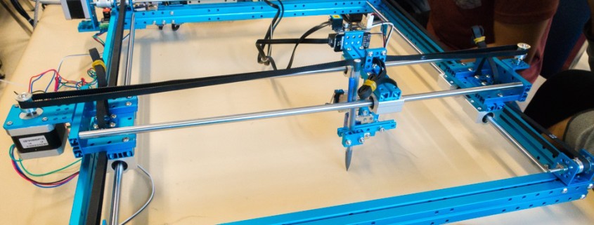
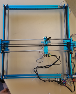
One of the main components on our PBS is the MakeBlock XY plotter. The XY plotter robot is originally a device that utilizes a pen or any other writing utensil to draw an image. Our design will involve the modification of the MakeBlock XY plotter in order to successfully become a pick and place SMD machine.

Software

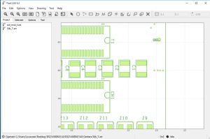
The XY plotter is equipped with two stepper motors that control the X and Y movements. These stepper motors will respond accordingly to locations set by the user through software. The files that the XY plotter reads are G-code (.CNC) files. After sending a .CNC file to the GCodeParser software, the XY plotter will begin reading coordinates and draw. This means a Gerber file to G-code file converter is crucial to our design.The two gerber files that needs to be converted to G-code are the solder mask top and silk top layers. These two layers will generate where each component needs to be soldered as well as a location name that can be referenced from a BOM (Build of Materials). I have researched into this and found a piece of software called FlatCam that could do this conversion.

Gremote

Figure 1 – GCodeParser Software

FlatCam Example

Figure 2 – FlatCam Software

Assembly

One of the issues that I came across while testing and assembling the XY plotter is that the instruction manual and firmware that came with the kit were outdated. Originally, the kit ships with an Arduino Leonardo but the newer model now ships with an Arduino Uno (Me Orion). This caused some error with the given firmware but after updating it with the proper firmware (from https://github.com/Makeblock-official) our system was up and running albeit with some errors. The limit switches on the XY plotter were not reading properly so the machine will continue moving even when the arm can no longer move. The movement of the XY plotter were also mirrored on both axis. If we wanted the plotter to move up, the plotter would instead move down. If we wanted the plotter to move left, the plotter would instead move right. The solution I found was that the connections given by Makeblock were wrong. After playing with the XY plotter for a while, I managed to get the connections so that the limit switches were reading properly and the movements were no longer mirrored.

XY plotter

Figure 3 – MakeBlock XY Plotter

Modifications

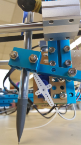
There are several modifications to this device that we have in mind. The accuracy of this device has a maximum error of 0.1 mm so we are thinking of implementing 5:1 geared stepper motors to control the X and Y axis. Trade-off studies for stepper motors will be conducted and presented in future blogs. We also have plans to modify the existing pen/marker system and implement a vacuum system with a nozzle in order to pick up and place down SMT components. Fortunately, the fittings on the XY plotter can already hold a pen so one of our ideas is to use a BIC pen casing and fasten on a luer syringe needle that has an opening diameter small enough to hold a 0402 component to the end. As it is right now, there is a micro servo that pushes the pen upwards and outwards when there is no need for it to have contact with the surface and after arriving at the intended location(s), the micro servo will release the pen back down. A trade-off study will need to be made to see whether or not this servo design will need modification.

Servo

Figure 4 – Micro Servo and Pencil Mechanism

The working area for the XY plotter is 310mm × 390mm (roughly 12.2″ x 15.4″) so there will be room for a 4″ x 3.2″ PCB, 4x 8mm reel feeders, and IC tray we are planning on implementing. Unfortunately, the XY plotter does not come with it’s own surface, meaning that the XY plotter will use whatever surface that it is placed on. In order to have a reliable flat surface that could heat up solder for future semesters to build on, there are plans to implement a blanchard grinding aluminum surface to the device.


Spring 2016 3D SMD: Preliminary Design Document

By: Bao Loc Doan (Project Manager)

Christine Vu (Systems Engineer)

Henry Nguyen (Electronics Engineer)

Nasser Alsharafi (Manufacturing)

Table of Contents

Program Objectives/Mission Profile

by Bao Loc Doan (Project Manager)

Program Objective Statement

When humans manually pick and place surface mount components onto a printed circuit board (PCB), there are problems with human accuracy and time efficiency. A pick and place surface mount device (SMD) is an automated device that can populate a PCB with surface mount components (resistors, capacitors, and IC chips) by referencing a Gerber file through the use of software. The pick and place SMD machine will be able to pick up the surface mount technology (SMT) components from 8 mm reel feeders and an integrated circuit (IC) tray and place the components down at the correct location until the board is finished. The customer has expressed the desire to create a pick and place SMD machine that can populate surface mount components as small as 0402 on all EE400D boards of Spring 2016 with the same specifications as the Madell Corporation Model DP2006-2.  The customer has expressed the desire to keep the budget of the project below $650 and finished before the end of Spring 2016.

Mission Profile

Once a gerber file provided by any project from EE400D up until Spring 2016 is uploaded, the pick and place SMD machine shall begin populating SMT components from four 8 mm reel feeders and one IC tray onto the PCB. The smallest SMT component that will be placed is component size 0402. The pick and place SMD machine will be modified from a Makeblock XY plotter and replicate the error specification of the Madell Corporation Model DP2006-2.

Requirements

Level 1 Program/Project Requirements

by Bao Loc Doan (Project Manager)

To satisfy our customer, a list of requirements that our end product needs to meet were created. These requirements will move the design forward and provide traceability to our program objectives and mission profile.

  1. The pick and place SMD machine shall be able to assemble all EE400D PCB’s by the end of Spring 2016.
  2. The pick and place SMD machine shall pick up a component and place down a component with a maximum of 0.05 mm error (specification of Madell Corporation Model DP2006-2).
  3. Software for the pick and place SMD machine shall accept all Gerber files of EE400D projects up until Spring 2016.
  4. The pick and place SMD machine shall have four 8mm reel feeders and one IC tray.
  5. SMT component size 0402 shall be the smallest component that the pick and place SMD machine can pick up. 
  6. Total cost of finished project must be under $650.
  7. Deadline to complete the pick and place SMD machine shall be before the end of Spring 2016.

Level 2 System/Subsystem Requirements

by Christine Vu (Systems Engineer)

Level 2 System and Level 2 Subsystem Requirements are listed below. The process of forming requirements is not only crucial to the overall design of the project but also difficult to form due to the customer’s needs and the nonlinearity of designing. Through many revisions, the level 2 requirements were officially determined. Because this project is new to the Arxterra blog, references were obtained through scholarly journal research and outside resources other than the Arxterra blog.

Source Material:

Arra, M. , Geiger, D. , Shangguan, D. , & Sjöberg, J. (2004). A study of smt assembly processes

for fine pitch csp packages. Soldering & Surface Mount Technology, 16(3), 16-21.

CadSoft Computer GmbH and CadSoft Inc. (2011). EAGLE Freeware. Retrieved from:

http://www.cadsoftusa.com/download-eagle/freeware/

Changzhou Douwei Electric Co. Ltd. (n.d.). 42BYG Stepping Motor. Datasheet.

Makeblock. (2014, June 9). XY Plotter 2.0 How it works? Retrieved from:

https://www.youtube.com/watch?v=gY0xMYrWBDg

Panasonic. (2014, Feb. 4). Precision Thick Film Chip Resistors. Datasheet.

Shenzhen Maker Works Technology Co., Ltd. (2013). X-Y Plotter Robot Kit. Retrieved from:

http://www.makeblock.cc/xy-plotter-robot-kit/

TCI Precision. (2005). Blanchard Grinding. Retrieved from: http://tciprecision.com/machine-ready-blanks/capabilities/Blanchard%20Grinding

Telecommunications Industry Association. (2001). TIA/EIA-568-B.1: Commercial Building

Telecommunications Cabling Standard.

VBsProjects. (2014, July 12). Homemade SMD Pick and Place Machine – complete cycle.

Retrieved from: https://www.youtube.com/watch?v=CRSLbo_8nTQ#t=7m34s

Notes on Requirements:

L2 – # – Level 2 System Requirements (i.e. L2 – 1)

L2 – #x – Level 2 Subsystem Requirements (i.e. L2 – 1a)

L2 – 1 Working area must be within 12.2”x15.35” (310mmx390mm) based on the Makeblock X-Y Plotter.

Explanation: The MakeBlock X-Y Plotter Robot Kit design specifications indicated the working area size as shown above (Shenzhen Maker Works Technology Co., Ltd., 2013). The working area is the area that the motors can move. This requirement will be verified through the use of a measuring tape tool. Tolerances will be taken account depending on the measuring tape that will be used.

L2-1a   Working Area shall fit a 4″ x 3.2″ PCB for EE400D students.

Explanation: EE400D Students will be using EagleCAD software to design their PCB.

The free version limits the PCB design size as 4” x 3.2” (CadSoft Computer GmbH and CadSoft Inc., 2011). This can be verified by the use of a measurement tape tool.

L2-1b  Surface to hold PCB shall be smooth with dimension tolerances to ±.001″, parallelism to .001″, and flatness to .001″.

Explanation: The process to place SMT components will begin with the application of solder paste by hand. This requires a very smooth surface that may require Blanchard grinding. These tolerances were taken from industrial Blanchard grinding standards (TCI Precision, 2005). This will be verified from the company that we plan on using.

L2-1c   PCBs laid out for assembly shall be on a surface at 0° with respect to the floor. A test shall be used to determine a safe tolerance.

Explanation: To improve precision, it is important to ensure that the machine will run in a straight line and parallel to the floor. This will keep the SMT components from falling off the PCB. A digital leveler will be used. Tolerances will depend on the leveler used.

L2-1d  All wires shall refrain from contact with the working surface.

Explanation: The Makeblock X-Y Plotter lacks the placement of wires. During plotting, wires are touching the surface (Makeblock, 2014). This should be avoided due to the addition of more wires, reel feeders, and IC trays in the working area. Wires dragging against the surface may also cause problems with wire protection.

L2-1e   All wires using RJ25 connectors shall have a minimum bend radius of 4x its diameter.

Explanation: The pick and place SMD machine has repetitive movement, where a vacuum system will pick up a SMT component and place it down a PCB one at a time. Since wires will be moving along the vacuum system, repetitive movement may affect the lifespan of the wires. Therefore, a general rule-of-thumb to prevent wire fatigue is to set a minimum bend radius of 4 times its diameter (Telecommunications Industry Association, 2001). The bend radius shall be measured from the start of the curve to the end of the curve using measuring tape. Tolerances will depend on the tool being used.

L2-1f   A clamping system shall hold all PCBs for EE400D students with maximum size 4″ x 3.2″.

Explanation: A clamping system will provide stability when the vacuum system is placing down the SMT components and indicate the maximum PCB size 4” x 3.2”, which is the limited PCB size for the free version of EagleCAD (CadSoft Computer GmbH and CadSoft Inc., 2011). This will be verified by clamping a 4” x 3.2” PCB. The clamped PCB should not be able to move once the machine is operating.

L2 – 2 The pick and place SMD machine shall pick up and place down all required integrated circuit chips according to EE400D PCB’s provided up until Spring 2016.

Explanation: The purpose of a pick and place SMD machine is to assemble a PCB design given by EE400D Students. It is important to note that integrated chips will also be placed down. This will be verified by the provided Gerber file.

L2-2a   A vacuum system shall pick up all required IC chips according to EE400D PCB’s provided.

Explanation: A vacuum system is the subsystem that will be used to pick up SMT components such as the integrated circuit (IC) chip. It also indicates that a vacuum system must be strong enough to hold the IC chip. This will be verified by testing the worst-case scenario, where the heaviest IC chip will be picked up by the vacuum system.  Explanation of the duration will be indicated in the next requirement, L2-2b.

L2-2b  Duration of suction to pick up IC chips shall begin from picking at IC tray to the placement on the PCB.

Explanation: Although picking up the SMT components are lightweight, it may be important to verify the duration of how long the vacuum system takes to pick up a component and place it on the PCB. A stopwatch will be used to time the process.

L2-2c   A solenoid valve shall close airway of the vacuum tubing each time IC chips are placed down.

Explanation: The vacuum system will be controlled through the opening and closing of a solenoid valve. This can be verified by testing the software to control the solenoid valve picking and placing the IC chip. This requirement is also noted for the rest of the SMT components in L2-8b.

L2 – 3 Pick and place SMD machine shall self-correct all orientation of IC chips before placement.      

Explanation: This requirement is to ensure that the pick and place machine is able to auto-orientate IC chips in case the chip is placed incorrectly on the IC tray. This can be verified through testing of the worse-case IC chip.

L2-3a   A sensor area shall detect the number of pins on IC chips.

Explanation: A feature that may be included to support our pick and place SMD machine is to create an area to correct the configuration of the IC chip when it is removed from the IC tray. This idea was based on one of a homemade pick and place SMD machine (VBsProjects, 2014).

L2-3b  In order to keep suction of the IC chip after pick-up, all IC chips shall be rotated about the A-axis.

Explanation: As stated in L2-3a, it is important to note how the IC chip will be corrected. That is, a motor may be used to move about the A-axis. VBsProjects (2014) demonstrates how the IC chip will be corrected. This will be verified by test – an IC chip will be picked up by the vacuum system and taken to the sensor area, where it will be corrected.

L2 – 4  Makeblock X-Y Plotter motors shall be modified to a maximum of 0.05 mm error.        

Explanation: The Makeblock X-Y Plotter online specifications indicate that the precision error is 0.1 mm (Shenzhen Maker Works Technology Co., Ltd., 2013). Calculations may be verified based on the distance between the SMT mounting holes (Arra etc., 2004).  

L2-4a   Resolution of all axes motors shall be less than 1.8°/step.

Explanation: The Makeblock X-Y plotter uses 42BYG Stepper motors to control the x-axis and y-axis, which indicate a resolution of 1.8°/step (Changzhou Douwei Electric Co. Ltd., n.d.). To improve the precision, a possible solution is to switch the stepper motors into better ones. This may be verified through the use of datasheets.

L2-4b  Z-axis motor shall move the vacuum system at 90° with a tolerance of 1° with respect to the floor.

Explanation: The Z-axis control on the Makeblock X-Y plotter uses a servo motor that moves up and down at an angle (Makeblock, 2014). If the z-axis is not modified, then the vacuum tubing may be bent and the vacuum system will not function properly if it is picking up the SMT components at an angle.

L2 – 5 Software shall translate all Gerber files from EE400D PCB’s to G-Code files.     

Explanation: The Makeblock X-Y Plotter plots using G-code files. Arduino sketches have already been made to control the motors.

L2-5a   Software shall include all x-y coordinates for pick and place SMD machine to read.

Explanation: G-Code will be viewed on CNCViewer, a program that can present the locations of the SMT components on a PCB.

L2 – 6: All SMT resistors and capacitors shall remain in cut-tape of the reel feeders until the vacuum nozzle is ready to pick up the component.     

Explanation: This requirement is to acknowledge that the reel feeders are secure and in place. This will be verified using a checklist – determine whether the vacuum nozzle moves other SMT components when the nozzle picks up one SMT component, determine whether the motors cause vibrations of the working area, and determine whether the SMT components will be isolated while the system is placing the components.

L2-6a   Reel feeders shall be placed within working area, 12.2”x15.35”(310mmx390mm).

Explanation: Because our working area is confined to the Makeblock X-Y Plotter Robot Kit (Shenzhen Maker Works Technology Co., Ltd., 2013), the vacuum system must be able to reach the SMT components. Therefore, the reel feeders must be placed in an area where it is reachable.

L2-6b  Bracket to hold cut-tape of the reel feeders shall be higher than 1.10 mm.

Explanation: The reel feeder tape specifies the tape thickness to be 1.00 ± 0.10 mm (Panasonic, 2014). In order to hold the reel feeders in place, the bracket should be higher than this. This can be verified by placing the reel feeders in the bracket.

L2-6c   Micro servos shall automate all reel feeders.

Explanation: The pick and place SMD machine shall be automatic; therefore, a motor would be used to control each of the reel feeders. A trade-off study will be conducted on micro-servos.

L2-6d  All micro servos shall remove plastic covering from the reel feeder.

Explanation: A solution to control the feeder is to have a pulley attached to the micro servos. A specification on a pulley shall be determined.

L2 – 7: IC tray shall store all IC chips required for one PCB assembly.    

Explanation: The worst-case scenario will be used to determine the size of the IC tray.  

L2-7a   IC tray shall be placed within working area, 12.2”x15.35”(310mmx390mm).

Explanation: Similar to the L2-6a, the vacuum system must be able to reach the working area of the Makeblock X-Y Plotter Robot Kit (Shenzhen Maker Works Technology Co., Ltd., 2013).

L2 – 8: Vacuum system shall be able to pick up all SMT components as small as size 0402.

Explanation: This requirement was based on the customer requirement to pick up small components. This will be verified by picking up the SMT component size 0402.

L2-8a   Vacuum nozzle shall be smaller than 0.50 ± 0.05 mm.

Explanation: The nozzle size is based on the smallest component to pick up, which is 0402. According to the datasheet, SMT size 0402, 0.05 0.50 ± 0.05 mm (Panasonic, 2014)

L2-8b  A solenoid valve shall close airway of the vacuum tubing each time SMT resistor and capacitor components are placed down.

Explanation: Similar to L2-2c, a solenoid valve will be used to control the passageways of the vacuum tubing. A test shall be conducted to control the solenoid valve with ArduinoUno.


Design Innovation

Creativity Presentation

System/Subsystem Design

Product Breakdown Structure

By Christine Vu (Systems Engineer) and Henry Nguyen (Electronics Engineer)

Product Breakdown Structure


Figure 1. Product Breakdown Structure

The Product Breakdown Structure (PBS) shows all the functional blocks of our pick and place 3D SMD machine. The hardware is split into three different categories: Component Feeders, Vacuum Head, and X-Y Table. We will need a minimum of 4x micro servos to control our 4x 8mm reel feeders and an IC chip tray. The Vacuum head will consist of a vacuum to suction the components, a syringe or vacuum pen to pick up our components, a solenoid valve to block airflow and allow our components to be placed, and finally a stepper motor for rotation of the A axis. The X-Y Table is purchased from MakeBlock; however, we will need an aluminum surface table, slider rods, stepper motors, and calibration sensors to orientate our components. For software, we plan on using Arduino to program the Arduino Uno and Me Orion microcontrollers. Software must be able to convert Gerber files into G-code which can be read by our Me Orion microcontroller. We will need to be able to control all axis of our machine, the calibration sensor, component feeders, and solenoid valve through software.

Electronic System Design

by Henry Nguyen (Electronics Engineer)

Source Material

Me Orion:

Me Stepper Driver:

System Block Diagram

System Block Diagram

Fig. 2. System Block Diagram

The image above is the system block diagram for our pick and place 3D SMD Machine. We will have 4 stepper motors, 4 micro servos, a vacuum, and a solenoid valve as our actuators. The 4 stepper motors are used to control our axis on our machine. We will have a X,Y,Z, and A axis. The A axis is for the rotating our vacuum nozzle in order to orientate our integrated circuits in the right position to place onto our PCB. We will also have 4 micro servos to control our reel feeders. We are planning on using these servos to move our components forward after our machine picks up the component from the reel feeders. The solenoid valve is to control our vacuum. Our vacuum will be constantly running on a separate power source. The solenoid valve will close off the vacuum to prevent suction. This will allow our components to be placed onto our PCB after our machine picks it up.

Interface Definition

Interface Matrix

Fig. 3. Interface Matrix

The image above is the interface matrix for our pick and place 3D SMD machine. We will be utilizing an Arduino Uno, Me Orion, and Me Stepper Driver. Me Orion and the Me Stepper Driver came with our X-Y Plotter. This Me Orion is based off of an Arduino Uno, which will allow us to code using Arduino, Scratch. and AduBlock. We will be using this microcontroller because it has 8 RJ25 ports which will be useful for all of our actuators. The Me Stepper Driver will be used to precisely control our stepper motors by operating our motors in full, half, quarter, eighth, and sixteenth step modes. This modes can be easily changed using the built-in DIP Switch. We will need 4 Me Stepper Drivers in order to control all of our stepper motors on each axis (x,y,z,A).

Me Orion Schematic

Fig. 4. Me Orion Schematic

Me Stepper Driver Schematic

Fig. 5. Me Stepper Driver Schematic

Specification for  Me Orion:

Operating Voltage: 6-12V DC power;

Microcontroller: ATmega238;

Detecting Angle: prefer at 30 degree angle;

Dimension: 80 x 60 x 18 mm (Length x Width x Height);

Specification for Me Stepper Driver:

  • Max current: ±1.35A
  • Max motor drive voltage: 25V    
  • Note: Me BaseBoard max supply  voltage 12V
  • Logic voltage: 5V
  • Dimensions: 48mm*24mm(Length × Width)

Mechanical Design

By Nasser Alsharafi (Manufacturing)

In this part of the project for the XY plotter I am coming up with the design of a Reel Feeder. The main purpose of a reel feeder is to feed the machine with the surface mounted parts. The reel feeder is made of aluminum. The main function of the Reel Feeder wheel is to roll and pass on the parts to the Reel Feeder base, which then the parts will be picked up by the vacuum.

FeederReelAssembly

Fig. 6. Complete reel feeder assembly 3D model

Reel Feeder Base

Fig. 7. Reel feeder base

The base sheet of the reel feeder has four channels called the grooves in which the tape passes through. The base sheet of the reel feeder has a length of 270 mm and a width of 82 mm. Each of the grooves on the base sheet of the reel feeder has a width of 8 mm. The main function of the reel feeder is to guide the tape to the part of the feeder where the chip is first pulled and then picked by a vacuum pen. This action helps in preparation of the next chip. After, the chip is taken by the vacuum pen and is placed on the PBC board.

Reel Feeder Wheel

Fig. 8. Reel feeder wheel

Initial Sketch of Reel Feeder Base

Fig. 9. Drawing of initial reel feeder base

Currently, our reel feeder is manual, so there can be further improvements by making the reel feeder automatic. In order to make the reel feeder automatic, I have to design a mounting bracket for 4 micro-servos. Each channel has single micro-servo to pull back the tape while pushing the reel forward. This will be implemented by working with Henry Nguyen to control the micro-servos.   

Design and Unique Tasks

By Henry Nguyen (Electronics Engineer)

  • Work with our X-Y Plotter and given programs in order to see how to control our actuators through software (02/19/16 – 02/28/16).
  • Research Flatcam which can take Gerber files and generate G-Code for isolation routing.
    • This is for our precision software that will tell our machine exactly where to pick and place components (02/19/16 – 02/28/16)
  • Look for local connections and prices for our aluminum surface table by 02/28/16.
  • Review DIY tutorials on how to configure an aquarium pump into a vacuum system (02/22/16).
  • Understand how to define actuators and power subsystems.
    • President Watts said he will review this in our division meeting (02/20/16).
  • Research how to incorporate gyro, accelerometer, and/or magnetometer into inertial measurement unit in order to measure the angular rotation of our A-axis stepper motor (03/18/16).

 

Spring 2016 3D SMD: Research Project

By: Bao Loc Doan (Project Manager)

Christine Vu (Systems Engineer)

Henry Nguyen (Electronics Engineer)

Nasser Alsharafi (Manufacturing)

Project Manager Research

Bao Loc Doan (Project Manager)

Mission Objective

When humans manually pick and place surface mount components onto a printed circuit board (PCB), there are problems with human accuracy and time efficiency. A pick and place surface mount device (SMD) is an automated device that can populate a printed circuit board (PCB) with surface mount components (resistors, capacitors, and IC chips) by referencing a Gerber file. The SMD pick and place machine will be able to pick the surface mount components up and place the components down at the correct location until the board is finished. The objective of this project is to create a pick and place SMD machine and the customer has expressed the desire to keep the overall budget of the project to be around $600.

Creativity

All creative ideas and brainstorming were done prior to establishing a firm base. You can read about our ideas given below in the link.

https://docs.google.com/presentation/d/1F_2NlVyMoYl47WXqDsclBF27teGJwjQjFWzvZX9yafo/edit?usp=sharing

Level 1 Requirements

To satisfy our gracious and generous customer, a list of requirements that our end product needs to meet were created. These requirements takes into account functionality, appearance, and price.

  1. The pick and place SMD machine shall pick up the component and place down the component with a 0.05 mm error (specification of Madell Corporation Model DP2006-2) .
  2. The pick and place SMD machine shall be able to complete at least one PCB.
  3. Arduino software for the pick and place SMD machine shall accept accurately at least one Gerber file per requirement of the course.
  4. The pick and place SMD machine shall operate automatically after pressing start once.
  5. The pick and place SMD machine shall be able to pick up from 4x 8mm reel feeders and an IC tray.
  6. Total cost of finished project must be under $600.
  7. Deadline to complete the pick and place SMD machine shall be before the end of Spring Semester 2016.

Work Breakdown Structure

The goal is to produce a working prototype by the end of the school semester (approximately 15 weeks). In order to meet that goal, a WBS (Work Breakdown Structure) needed to be created in order to allow group members to focus on their own specific divisions. The following graph is the WBS that I and our system engineer, Christine Vu, developed.
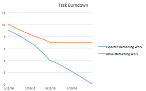
 

Work Breakdown Structure

Figure 1 – Work Breakdown Structure

Product Breakdown Structure

Now that we’ve developed what our WBS is, the next step that we took was developing a PBS (Product Breakdown Structure). The PBS will allows us to map out the key components of our design.

Product Breakdown Structure

Figure 2 – Product Breakdown Structure

Budget

Our preliminary budget ended up being slightly under the budget given by our customer. The bulk of the price (~$300) will be from the XY plotter that will be purchased from Ebay. Outsource labor takes into account the costs that the machinist will charge for their services. This number is merely an estimation and the number was given to me by a connection that I have to a machinist that would be willing to work with us.

Budget

Figure 3 – Estimated Budget

Systems Engineer Research

b345t fr0m th3 345t

Christine Vu (Systems Engineer)

As a systems engineer, one must consider the components that make up the project design to formulate requirements, functionality, and progress.


For the pick and place Surface Mount Device (SMD) machine, we had to include both the course’s requirements and requirements that will progress the design. In the requirements section, words like “shall”,  “must”, and “will” are equivalent and are mandatory to move the design forward. Words like “may” are suggestions that are optional to the design. It is also important to note that the table to hold PCB and the X-Y Table is used simultaneously and are equivalent. During the requirement-forming process, Henry Nguyen (Electronics) and I went over subsystem requirements while Bao Loc Doan (Project Manager) and I went over system requirements.

Level 2 System Requirements

Level 1 Requirements (L1):

  1. Pick and place SMD machine shall pick up the component and place down the component with a 0.05 mm error.

Level 2 System Requirement (L2):

L2 -1    SMT component shall have a vibration displacement of less than 0.05 mm from its original spot during the entire operation. This requirement is so that the placement of the SMT components would prevent incrementing error.

   1. The pick and place SMD machine shall be able to complete at least one PCB.

Level 2 System Requirement:

L2 – 2   Noise level of pick and place SMD machine during run-time shall be under 40 dB. This is a requirement so it would not disturb our customer.

  1. Software for pick and place 3D SMD machine must be able to translate maximum PCB size of a 4” x 3.2” Gerber file schematic.

Level 2 System Requirement:

L2 -3    Gerber file shall include at least one 0402 component. This is per requirement of great leader Hill.

  1. Pick and place SMD machine shall operate automatically after pressing start once.

Level 2 System Requirement:

L2 – 4     Pick and place SMD machine shall send zero error feedback.

  1. Pick and place SMD machine shall be able to pick up from 4x 8mm reel feeders and an IC tray.

Level 2 System Requirement:

L2 – 5     Pick and place SMD machine shall be clear of debris during operation, which would be pieces that are not part of the SMT components and are larger than the 402 metric component (0.4 mm x 0.2 mm, or 0.0157” x 0.0079”) and include wires. This requirement is so that when the PCB board is placed on a smooth surface, the application of solder paste will not be interfered.

  1. Cost must be under $600.

Level 2 System Requirement:

L2 – 6     Pick and place SMD machine budget sheet shall be under $600.

  1. Deadline to complete pick and place SMD machine’s final assembly shall be before the end of Spring Semester 2016.

Level 2 System Requirement:

L2 – 7     Pick and place SMD machine assembly schedule shall be submitted before February 11, 2016 at 11:59 PM.


Initial System Block Diagram

This block diagram was based on the Arxterra blog posts on RosCo from Fall 2015.It was discovered that the pick and place SMD machine can be operated using stepper motors as found through videos as shown on the MakeBlock X-Y Plotter. Another YouTube channel provided the entire run-through of the pick and place 3D SMD machine assembly, Scientist Razz. References of these videos are shown at the end of this blog post.

System Block Diagram

Figure 1. Initial System Block Diagram will control stepper motors.


System Interface Matrix

Pins on motor shield will be determined after further research on the benefits of buying a shield designing one.

AVR Arduino Bluetooth
PD0 (RX) Digital Pin 0 TX
PD1 (TX) Digital Pin 1 RX
PD2 (INT0) Digital Pin 2 Motor Shield
PD3 (INT1) Digital Pin 3 H-Bridge
PD4 Digital Pin 4 H-Bridge
PD5 Digital Pin 5 H-Bridge
PD6 Digital Pin 6 H-Bridge
PD7 Digital Pin 7 3D SMD
PB0 Digital Pin 8 X-Axis Stepper
PB1 Digital Pin 9 Y-Axis Stepper
PB2 Digital Pin 10 Z-Axis Stepper
PB3 Digital Pin 11 A-Axis Stepper
PB4 Digital Pin 12
PB6 Digital Pin 13
PC0 (ADC0) Analog Pin 0 (Digital Pin 14)
PC1 (ADC1) Analog Pin 1 (Digital Pin 15)
PC2 (ADC2) Analog Pin 2 (Digital Pin 16)
PC3 (ADC3) Analog Pin 3 (Digital Pin 17)
PC4 (ADC4) Analog Pin 4 (Digital Pin 18)
PC5 (ADC5) Analog Pin 5 (Digital Pin 19)
PC6 (ADC6) RESET

Figure 2. System Interface Matrix.

Validation Matrix:

Validation Product Activity Objective Method Results
Pick and place SMD Machine (Overall)
Customer will evaluate overall functionality and display of pick and place machine.
1.) Ensure that L2-1 and L2-2 are complied. 2.) Ensure that errors occurred during operation are picked up by machine per requirement L2-4. 3.) Ensure that machine is clean (clear of debris) per requirement L2-5. 3.) Evaluate overall budget costs per L2-6 and L2-24.
Test — Vibration displacement of SMT component must be measured using precision caliper with +/- 0.002 mm tolerance and presented to customer.
Test — Measurement of noise level may be used by phone application.
Analysis — To evaluate budget costs, documentation of purchased products and an excel sheet that includes all pick and place SMD machine components shall be submitted.
Gerber File
Customer will view specifications on Gerber file.
1.) Ensure L2-3, L2-20, and L2-21 are complied.
Analysis — Present Gerber file that would be used and include the smallest component 0402.
Analysis — Create software to translate 4″ x 3.2″ Gerber schematic.
Stepper Motor Operation
Customer shall evaluate motor display and software. This is combined because software will control the stepper motors.
1.) Ensure that L2-19, L2-20, and L2-21 are complied.
Test — Stepper motor temperature may be measured on the outer surface.
Test — Error must be recognized by the software. Errors may be orientation of integrated circuit chips.
3D Axis (X, Y, Z) Control
Customer will evaluate motion of motors.
1.) Ensure that L2-12, L2-13 are complied.
Test — Submit data of X- and Y-axes presenting a straight movement at an angle of 0 degrees with 2.5 degrees tolerance.
Test — Verification of Z-axes must present a straight movement of 90 +/- 2.5 degrees using data
Nozzle
Customer will evaluate overall functionality of nozzle.
1.) Ensure that L2-14, L2-15, and L2-16 are complied.
Test — Rotation of nozzle shall be controlled to present the 180 degree rotation.
Test — During vacuum system assembly, allow vacuum to be constantly on to hold the SMT component upwards and record time for 4 seconds.
Belt Pulley Customer will evaluate assembly of pulley. 1.) Ensure that L2-18 is complied. Test — Verification of belt width and pulley wheel width may be measured separately.
X-Y Table/Aluminum Surface
Customer will evaluate assembly of working surface area that is X-Y table/aluminum surface.
1.) Ensure that L2-8, L2-9, L2-10, L2-11, L2-21, L2-22, and L2-23 are complied.
Test — Measure table with an accurate, precise ruler to determine the dimensions of drilled holes and gap between clamp and PCB.
Test — Table slanting can be checked using a leveler or the pythagorean theorem based on dimensions measured by an accurate, precise ruler.
Wire Connections Customer will evaluate quality of wire assembly. 1.) Ensure that L2-17 is complied. Test — Verify that quality of wire connections are not strained and have slack.

Figure 3. Validation Matrix that covers Level 2 requirements. Deadline requirements were removed.


References:

MakeBlock X-Y Plotter:

http://www.makeblock.cc/xy-plotter-robot-kit/

Scientist Razz:

https://www.youtube.com/watch?v=1aL7_8LJ4E8

42BYG Stepper Motor Datasheet:

http://www.micropik.com/PDF/42byg[1].pdf

System Block Diagram & Systems Interface Matrix was based on RosCo’s Fall 2015 Design:

http://arxterra.com/rosco-updated-interface-definition-fall-2015/

Gerber File Processing:

https://www.ucamco.com/files/downloads/file/81/the_gerber_file_format_specification.pdf


Electronic Engineer Research

Henry Nguyen (Electronic Engineer)

As an electronics and control engineer, we must consider possible softwares and hardware that help move our 3D SMD design process forward. An electronic engineer is responsible for several sub divisions such as PCB Design, Sensors, Actuators, and Power, and MCU Subsystem and Control Firmware. Due to this project being the first iteration of its kind, a lot of R&D needed to be done. PCB Design will be put on hold until it is required in the design.

PCB Design:

  1. We may need to design a PCB if the motor shield that comes with the X-Y Plotter does not power 4 H-Bridge due to an arduino output current of 40mA/
  2. Working from the interface matrix and block diagram created by our systems engineer (Christine Vu), we are required to design our Printed Circuit Board with maximum dimensions of 4”x3.2”.
  3. Create an electrical schematic in Eagle Cad.
  4. Create a Fritzing Diagram.
  5. Design and test circuit from our breadboard.

Sensors, Actuators, and Power:

  1. Stepper motor will rotate 180 degrees in order to pick up our components and orientate them on our PCB.
  2. Stepper motor are required for our vacuum head to move freely on our XY plotter.
  3. Determine power distribution of pick and place SMD machine.

MCU Subsystem and Control Firmware

  1. Write software that will control the vacuum head on our XY Plotter.
    1. Vacuum head on the A axis must be able to move freely within our X-Y working area of 10”x12”  +/- 2” tolerance.
    2. The actuator will also need another servo that can rotate the nozzle 180°in order to pick up components.
  2. Translate commands into control signals.
  3. Modify Brian Dorey’s software for Pick and Place in C# and use Visual Studio to write the application using  a smoothstepper ethernet board and Mach3.
    1. Based on Brian Dorey’s pick and place SMD, we will be legally using his software programs for our pick and place precision software.
      1. https://github.com/briandorey/pickandplacesoftware
    2. Find Gerber to Eagle translation
      1. http://www.cadsoftusa.com/downloads/file/eagle_pcb_power_tools5_06.exe
  4. Arduino may be used to control the feeder assembly
    1. https://github.com/briandorey/PNPControllerUSB/tree/master/atmel%20code

Subsystem Requirements

Level 1 Requirements (L1)

  1. Pick and Place SMD machine shall pick up the component and place down the component with a 0.05 mm error.

Level 2 Subsystem Requirements (L2 Sub):

Aluminum Table:

L2 – 8     Aluminum table will be 12.2047”x15.3543”(310mmx390mm) +/- 0.1” with small drilled holes in order to attach our clamping system.

L2 – 9     Table to hold PCB must be made of smooth aluminum with a clamping system which will be that holds the PCB with a gap of less than 0.5 mm.

L2 – 10     Table to hold PCB must be leveled at 0 +/- 2.5° with respect to the floor.

L2 – 11    Table to hold PCB shall be elevated to a minimum of 1” +/- 0.5” for solder paste heating.

Motor Movement:

L2 – 12     Motors moving in X-Y axes must be in a straight line at  0 +/- 2.5° with respect to the floor. The 2.5°tolerance is an estimate of human error. The physics of human error was only roughly studied due to the scope of this course.

L2 – 13     Motors moving in the Z-axis shall be moving in a straight line at 90 +/- 2.5° with respect to the floor.

L2 – 14     Motor that rotates the nozzle will be able to rotate 180° +/- 1°tolerance.

L2 – 15     At least one vacuum nozzle/head must be smaller than 0.4 mm x 0.2 mm (0.0157” x 0.0079”) by at least 0.1 mm +/- 0.05 mm. This size comes from the size of the smallest component, 0402 metric.

Vacuum System:

L2 – 16     Suction pressure of vacuum nozzle/head must be able to pick up integrated circuit components for at least 4 seconds.

L2 – 17     Wire connection configurations shall have a minimum bend radius of 11 times its diameter. This requirement is to relieve wire stress at rest and during operation.

L2 – 18     Width of belt to attach on pulley shall be less than 0.5 mm. This would help refrain the belt from slipping.

  1. Pick and place SMD machine shall be able to have a run-time of at least 4 hours.

Level 2 Subsystem Requirement:

L2 – 19     Temperature of stepper motor shall be under 131° +/- 1°Fahrenheit. This requirement is based on the 42BYG stepper motor that was used for the MakeBlock X-Y Plotter.

  1. Software for pick and place 3D SMD machine must be able to translate maximum PCB size of a 4” x 3.2” Gerber file schematic.

Level 2 Subsystem Requirement:

L2 – 20     Software shall translate with zero error.

  1. Pick and place SMD machine shall operate automatically after pressing start once.

Level 2 Subsystem Requirement:

L2 – 21     Software shall be able to recognize and self-correct all mistakes.

  1. Pick and Place SMD machine shall have  a maximum of 4x 8mm reel feeders and an IC tray.

Level 2 Subsystem Requirements:

L2 – 22     X-Y Table must be large enough to hold the standard free Eagle PCB dimensions (4” x 3.2”), with at least 5” around the PCB perimeter. The length of 5 inches is a safe measurement so that the PCB does not slip off during pick up.

L2 – 23     Size of working area shall be within 10”x12” with +/- 2” tolerance. This requirement is based on the X-Y Plotter from MakeBlock that we may be purchasing.

  1. Cost must be under $600.

Level 2 Subsystem Requirement:

L2 – 24     Components of the pick and place SMD machine shall list prices rounded to the nearest $1.

  1. Deadline to complete the pick and place SMD machine final assembly shall be before the end of Spring Semester 2016.

Level 2 Subsystem Requirement:

L2 – 25     X-Y Plotter, pick and place SMD surface, and vacuum system (nozzle and vacuum pump) shall arrive before March 25, 2016.

Plan

I watched several videos on Arduino and understand the general idea about coding in C; however, I am unsure if the application of the Arduino will only be used for our reel dispenser or also be used for our precision software for our 3D SMD project. Until we get our XY Plotter, stepper motors, and design, I will not be able to write any software until we know exactly what goes where. I also understand that Ryland Watts and Nick Lombardo are great sources to learn Arduino and C. When the time comes and my Electronics and Control position is necessary for working with Arduino, I will be sure to contact Ryland, Nick, and other knowledgeable sources. A lot of research was done on the specifications of X-Y plotter and and possible design ideas in order to proceed with our project.


Clamping System

Figure 1 – Clamping System

XY plotter robot

Figure 2 – XY Plotter Robot Kit

References:

Brian Dorey’s SMD Project

http://www.briandorey.com/category/DIY-Pick-and-Place


Manufacturing

Nasser Alsharafi (Manufacturing)

Vacuum System

The vacuum pump works as follows. Essentially the air compressor or vacuum pump is connected to a one-way check valve. The one way check valve is a standard mechanical device that cost around 12$. The one way check valve is connected to an electric solenoid. The solenoid is controlled via a microcontroller programmed for specific timing intervals. The size of the solenoid hose connection should be ¼”.

The solenoid then connects to the pick up needle that is specified below. The needle needs to be small enough to pick up the smallest SMD part that it can. The tank is not needed however can be useful if it is disconnected or inactive for a period of time.

Vacuum Pump

The vacuum system is currently being researched and optimized. One thought is an electric air compressor, and the other is a 1200CC aquarium pump. The one way check valve, solenoid, computer-programmed microcontroller, are already specified but can be changed as necessary later if the project is altered in the future. The nozzle is being researched. So far specification for a 0.41 by 0.19 nozzle have been found and priced at 30$. The aluminum surface can be custom ordered to any size necessary.

sparkfun vacuum

Figure 1 – Sparkfun Vacuum Pump

This is the Sparkfun Vacuum pump 12V. It cost around $15. It can work under 32° -120° F(0° -50°C). Most people who have used this device praised it for its quality. Most of the projects we researched online used this Vacuum pump for their pick and place projects. The only problem with is device that it might be noisy but since its relatively cheap we can try build a box that can reduce the noise. Also one of the methods that users reduced the noise for this pump is by running at lower voltage for example 8.5 volts, which was still able to lift a whole Bluetooth module. The barb connector is ¼” and should connect to another barb of same dimension.

An objective is that we want to keep the cost as low as we can. Perhaps, we would consider the electrical pumps as first, but if we want to make it cheaper possibly we could take the aquarium air pumps as an option. Aquarium Air pumps need to have the ability to make the tube pressured enough to pick the chips and place them at the board. As an example of an Aquarium Air pump we would consider Aqua Culture with 20 to 60 gallons, and its price is 7.61$. It has the ability to pump 1200 CC per minute. On the other hand, we have the electrical pumps that will be around 59$. Many reviews on the Aquarium Air state it has substituted the expensive electrical pumps very well.

Aquarium Air pump

Figure 2 – Aquarium Air Pump

Nozzle Head

After that we researched the nozzle head. We found multiple ways that people implemented the nozzle head. Our requirements list that our nozzle must be smaller than the smallest 0402 component, which is 0.4 mm x 0.2 mm. we found many nozzles that can work for our project and the following is an example.

Vacuum Nozzle

Figure 3 – Vacuum Nozzle


References:

Sparkfun Vacuum Pump:

https://www.sparkfun.com/products/10398

Nozzle Head:

http://www.aliexpress.com/store/product/SMT-MV-0402-NOZZLE/1457082_2050995547.html

Aquarium Air Pump:

http://www.walmart.com/ip/10532634?wmlspartner=wlpa&adid=22222222227001219214&wl0=&wl1=g&wl2=c&wl3=40341924752&wl4=&wl5=pla&wl6=56968315625&veh=sem