By: Intiser Kabir (Project Manager)
Approved By: Miguel Garcia (Quality Assurance)
Introduction
By Intiser Kabir (Project Manager)
The purpose of this document is to provide a closure to the Spring 2018 AT-ST Project. This document will provide linkages to all aspects of the project for a future generation, including our recommendations, what we learned, and what we should have learned beforehand. We will also provide what went wrong with our project as well. It is recommended to use the table of contents to jump to sections if needed.
Project Members:
Intiser Kabir (Project Manager)
Danny Pham (Manufacturing and Design)
Shweta Hebbalkar (Electronics and Controls – Hardware)
Samuel Yoo (Electronics and Controls – Software)
Joseph Cho (Missions, System, and Testing)
Executive Summary
By: Intiser Kabir (Project Manager)
Mission Objective
The AT-ST Walker BiPed was inspired by Spring 2017 Velociraptor which uses the Theo Jansen’s leg design as the walking feature. We ended up having to choose this design from the negotiations made by both the customer and the Robot Company project teams. While our robot is a direct spin-off of the Velociraptor, we are incorporating a lot of their designs in order to not be mistaken as the BiPed team within the Robot Company. The AT-ST Walker BiPed should be able to go through both S’18 Project and Mission Objectives and EE400D S’18 Project and Mission Objectives documents.
Missions Objective: Source: https://docs.google.com/document/d/1kwObe9HkGBeCjMYAETA5GiChyxhY1o6bpcmhWKbNFv8/edit?ts=5aa836cb#heading=h.m8d2ovwute3k
Key Features
Shaft Encoders
As a way of controlling the motors moving at different speed as well as helping our AT-ST robot to walk and turn. The Shaft Encoder is used to help see our motor’s movement as our AT-ST walks forward.
Ultrasonic Sensor
As a way of avoidance control, the Ultrasonic Sensor is used to help the AT-ST avoid getting into any sort of collision when navigating through the maze.
UV Sensor
As a method for line following, the AT-ST use 2 UV Sensors and 2 UV lights to pick up UV color as it navigates through the maze.
Theo Jansen Leg
The method we are using for walking was inspired by the Dutch artist Theo Jansen. He made robots powered by wind as it walks around. We use his method to create our legs to get the same method.
Micro Motor
To control the leg movement we decided to use Micro Motors since it consumes less current and is compatible with the Shaft Encoders
Project Requirements
The Level 1 and Level 2 requirements follow both the S’18 Project and Mission Objectives and EE400D S’18 Project and Mission Objectives documents. Also what our team is hoping to accomplish by the deadline May 15. Level 1 is for general requirements that the AT-ST is hoping to achieve. Level 2 requirements go down to specific requirements for each member hoping to accomplish.
Level 1 Requirements
- AT-ST shall walk on a level surface
- AT-ST shall use Theo Jansen leg design
- AT-ST shall look like an AT-ST Walker from Star Wars
- AT-ST shall turn left, right or turn around
- AT-ST shall support its own weight
- AT-ST shall not exceed pass the size of 6’’x 6’’
- AT-ST shall not walk through walls
- AT-ST shall walk straight
- AT-ST should walk backward
- AT-ST should have a dynamic walk
- AT-ST should jump.
- AT-ST shall not exceed the budget of $250
Level 2 Sub – MST Requirements
- AT-ST shall use Gyro to obtain information for calculating the center of gravity.
- The 3DoT Board shall receive commands from the Arxterra app via Bluetooth Transceiver. It will decode and transmit data to servos, PCB and other components of the robot.
- The power source shall be able to fit inside our robot and must be integrated into the AT-ST such that it doesn’t conflict with the functionality of the robot.
Level 2 Sub – Electronic Requirements
- AT-ST shall use 2 DC Motor to move the legs (1 per leg).
- AT-ST shall use a Servo Motor to adjust the center of gravity of the robot so it can turn
- The Battery’s duration shall last up to an hour.
- AT-ST shall use 2 shaft encoder to keep track of the leg motion
- AT-ST shall utilize 2 Lithium Ion Battery – 2Ah for its power supply.
- AT-ST shall use an ultrasonic sensor to sense other robots within a 0.5-meter radius
- AT-ST shall use UV sensor to navigate through the maze.
Level 2 Sub – Manufacturing Requirements
- AT-ST shall have a total weight of 600 g and weight will be properly distributed to the body and legs to support its own weight while walking.
- AT-ST shall not exceed dimensions of 6” x 6” in order to fit in the maze and walk and properly turn without hitting the walls in the maze.
- AT-ST shall have its body 3D printed (ABS)
- AT-ST shall have legs 3D printed (ABS)
Reference:
- Verification Test Plan: https://www.arxterra.com/at-st-verification-test-plan/
- Preliminary Blog: linked once Published
- L1 & L2 Blog: https://www.arxterra.com/spring-2018-at-st-project-specific-requirements-and-objective-l1l2/
- Spring 2017 Velociraptor: https://www.arxterra.com/spring-2017-velociraptor-final-project-summary/
- https://www.arxterra.com/spring-2017-velociraptor-preliminary-design-documentation/
- Missions Objective: Source: https://docs.google.com/document/d/1kwObe9HkGBeCjMYAETA5GiChyxhY1o6bpcmhWKbNFv8/edit?ts=5aa836cb#heading=h.m8d2ovwute3k
System Design
System Block Diagram
By: Joseph Cho (Mission Systems and Testing)
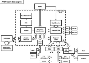
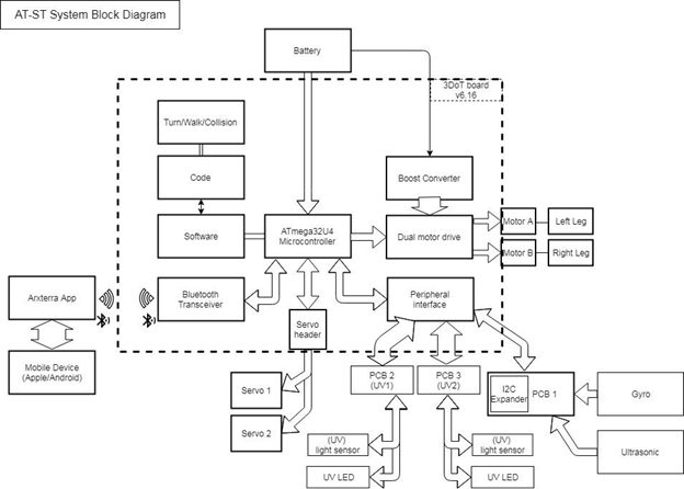
Figure 1: System Block Diagram
The System block diagram above for AT-ST help visualize the system of the AT-ST. The 3DoT board uses ATmega32U4 as the microcontroller. The 3DoT board consists of a microcontroller, Bluetooth transceiver, servo header and dual motor driver. The 3DoT board (v6) will also be connected to the servos, motors and main custom PCB. PCB1 will be the master PCB that routes all input and output for the sensors. PCB 2 and PCB 3 are used for UV sensors which will be connected to the I2C expander on PCB 1. Bluetooth transceiver will connect to a mobile device using the Arxterra app via Bluetooth.
To read about it,
Blog post: https://www.arxterra.com/at-st-system-block-diagram/
Interface Matrix
By: Joseph Cho
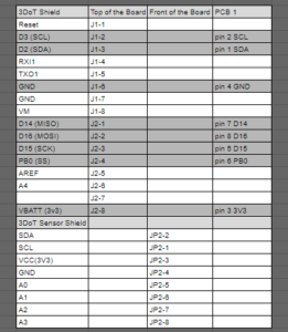
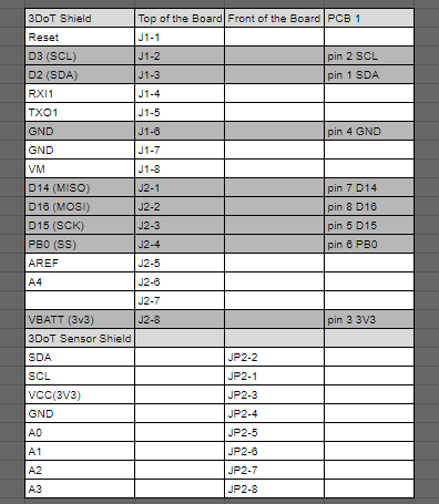
Figure 2: 3DoT Interface Matrix
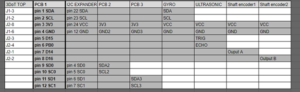
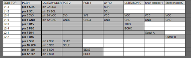
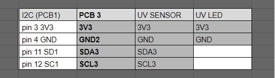
Figure 3: PCB 1 Interface Matrix
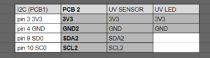
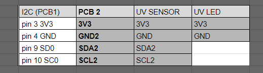
Figure 4: Custom PCB #2
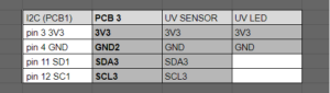
Figure 5: Custom PCB #3
The interface matrix above shows the allocations of the components to the 3DoT board. List of connections to PCB1: ultrasonic sensor, gyroscope, shaft encoder 1, shaft encoder 2, PCB2 and PCB3.
On PCB1, there will be an I2C expander for the two UV sensors that share the same I2C address (0x60). The gyroscope has I2C address of 0x68 or 0x69, so it will not conflict with the UV sensor. PCB2 and PCB3 will be connected to PCB1 to utilize the I2C expander.
List of connections that are not shown in the interface matrix: servo header connecting to two servos and the motor driver connecting to two motors. The figure below shows an older version of the 3DoT board that shows the I/O headers. The new version of the 3DoT board has the motor driver, Bluetooth, and servo headers integrated internally, so they are not listed on the interface matrix.
To Read More: https://www.arxterra.com/at-st_interface_matrix/
Resource Reports
By Joseph Cho (Missions, System and Testing)
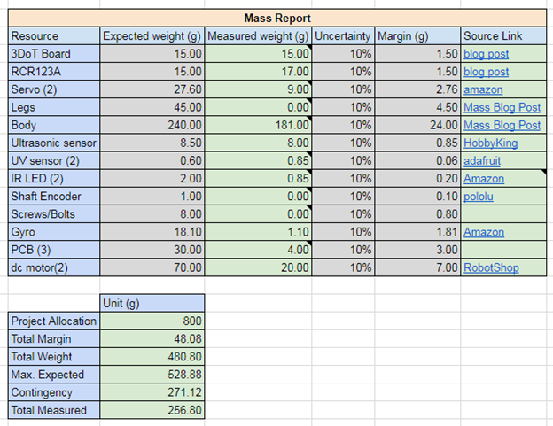
The resource report contains three parts: Mass report, power report, and cost report). These reports will be covering the resources’ mass, power, and cost. An estimate of the total mass will be shown on the mass report. For power report, the current values were taken from previous projects’ blog posts as reference. Lastly, cost report will show that the AT-ST project is within the budget.
Power Budget
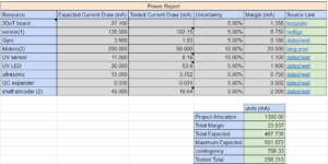
Figure 6, Power Report
To Read more about Power Report: https://www.arxterra.com/at-st-resource-reports-mass-power-and-cost/
Power Budget: https://www.arxterra.com/at-st-power-budget/
Mass Report
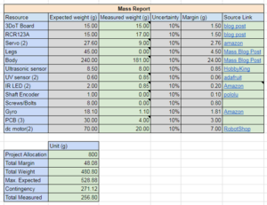
Figure 7: Mass Report
To Read More: https://www.arxterra.com/at-st-mass-report/
Cost Report
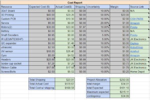
Figure 8: Cost Report

Figure 9: Extra Cost (included in the Cost Report)
To Read more Cost Report: https://www.arxterra.com/at-st-resource-reports-mass-power-and-cost/
Preliminary Blog to see old report: Link will be provided when Published
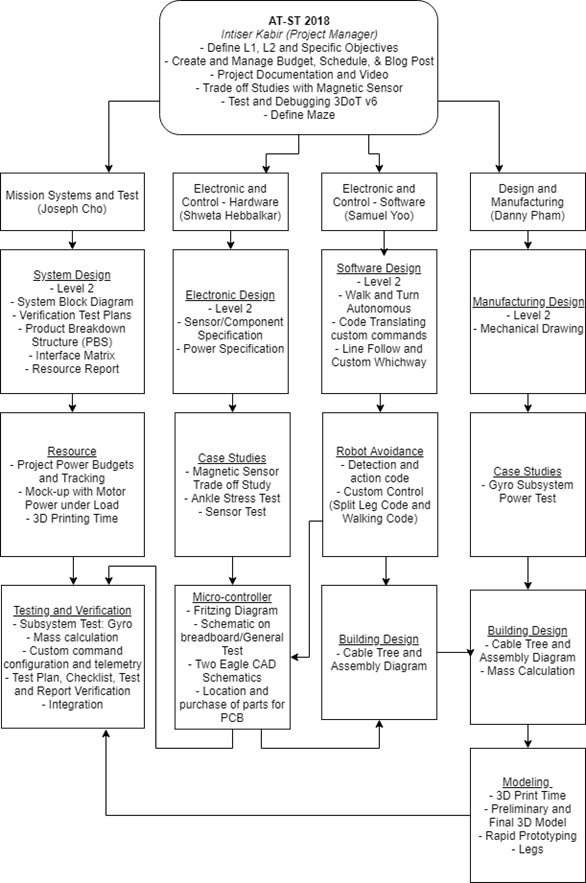
Manufacturing Design
By: Danny Pham (Manufacturing and Design)
Mechanical Drawing
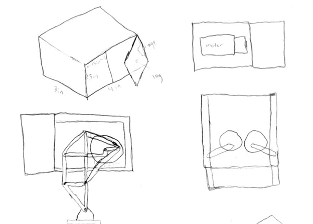
For our robot to walk and turn successfully, we will be designing elements of the robot that will be able to balance itself and move smoothly. The AT-ST walker design will incorporate parts of the velociraptor and biped design from previous semesters. The AT-ST will also incorporate dc motors instead of servos, so we switched out from our previous Titrus III leg design. In our case, our robot designs will be using the Theo Jansen leg design and split leg function that the previous 2017 Spring velociraptor project used.
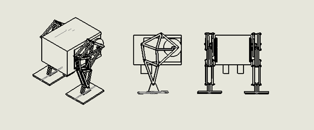
Initial Design – Mechanical Drawing

Figure 10, 1st preliminary concept drawing.
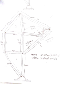
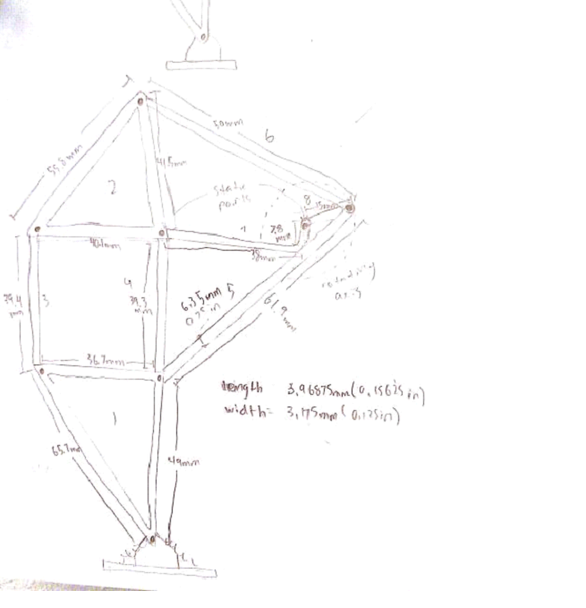
Figure 11, Theo Jansen leg design
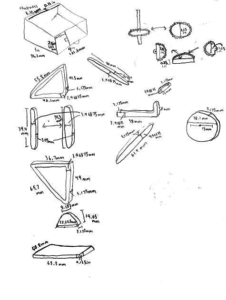
Figure 12, Measurement Parts

Figure 13: Mechanical design of AT-ST
To Read More: https://www.arxterra.com/spring-2018-at-st-mechanical-drawings/
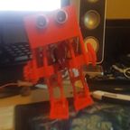
Preliminary Prototype
By: Danny Pham (Manufacturing and Design)
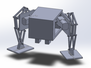
Figure 14: Preliminary Model of AT-ST
This is our first model that incorporated the Theo Jansen legs and split leg mechanism. I used a box for the body and implemented door hinges on the side that would act as the split leg mechanism that turns the legs. There are servos inside the box that are connected to these panels, and the servos would move the panel in and out to turn the legs. The DC motors are planted on the other side of the panels inside the box, and the motor is connected directly to the Theo Jansen leg. The motor rotates the leg and creates the walking motion for the robot.
To Read More: https://www.arxterra.com/at-st-preliminary-model/
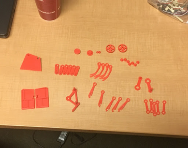
Rapid Prototyping

Figure 15: These are the components we printed that will be put together to build the legs of the robot.
We printed the pieces with PLA so the printed components are brittle and easy to break. We had to replace these with new reprints and increased the number of layers and density so that the components weren’t as easy to break when putting the bot together.

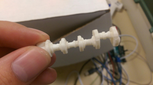
Figure 16: Rotation Shaft
First print of the rotating shaft. It is a complex piece to print because of alternating circles and different sizes throughout the shaft. It was also very easy to snap because we printed it vertically.
To read more: https://www.arxterra.com/spring-2018-at-st-rapid-prototyping/
Cable Tree Diagram
By: Danny Pham (Manufacturing and Design) and Samuel Yoo (Electronics and Control – Software)
The cabling of this diagram contains the servo, ultrasonic sensor, and the dc micro motors. All of the cable used to connect the components were ribbon cable. These cables would make the cabling look cleaner compared to lose wires.
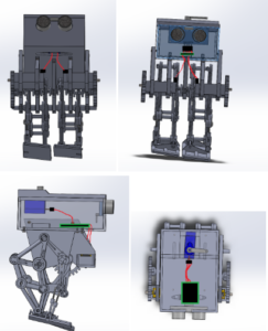
Figure 17: Cable Tree
To Read More: https://www.arxterra.com/spring-2018-at-st-cable-tree/
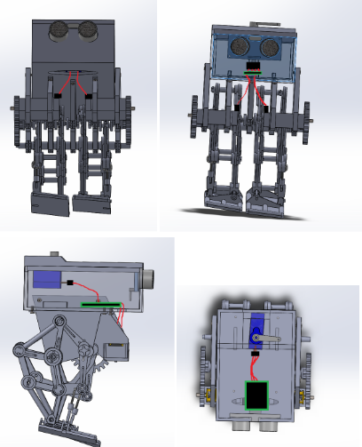
Final Prototype
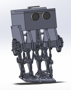
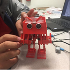
Figure 18: Final Model
There are a few things I would fix for this model. Because there are gaps between components in the model, it would be nice to hide some of the wires with panels that covered these gaps. I would also fix some of the screw holes for the model. In Solidworks, it is easy to reach these holes to put screws in, but for the actual model, it can be impossible to reach. Finally, I would adjust some holes in the box. When you 3D print the part, the 3D printing can deform the part so that your dimensions for size and holes are off. We had to sand down the parts to fix that. The issue for this type of design is that these components were not meant to be 3D printed. The design worked as intended but could be improved on. A solution to this is to redesign each component so that it is held together by screws instead of the connections and edges already on the kit components. Redesigning the components to basic connector shapes and using more screws to hold each part together will allow for easier 3D printing but maintaining the function of this design.
To Read More: https://www.arxterra.com/spring-2018-at-st-final-model/
3D Printing
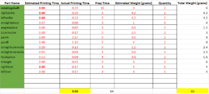
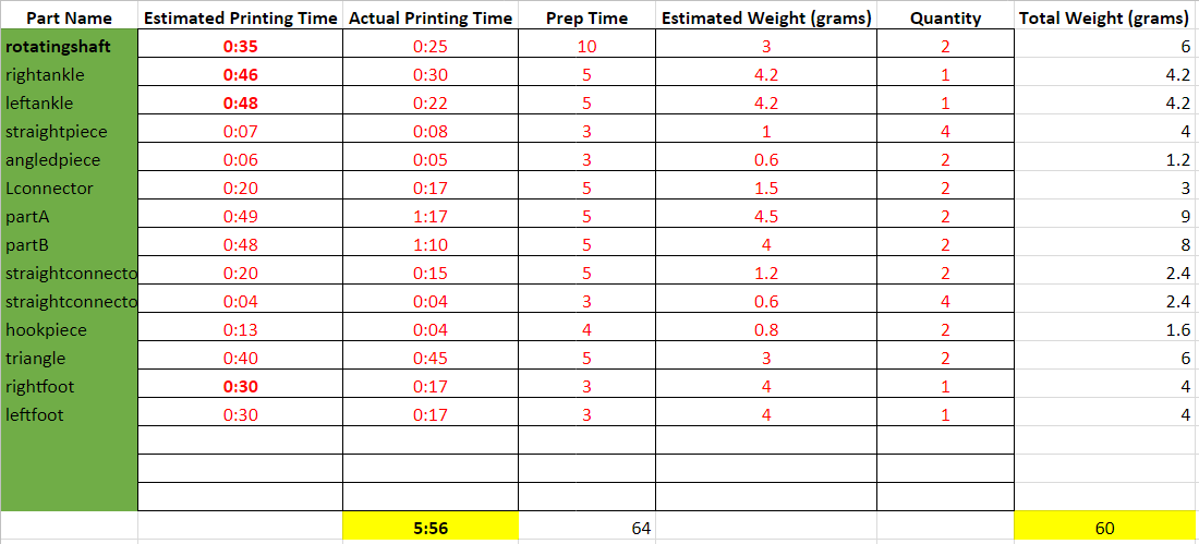
Figure 18: Print times
The Actual print time without the laser printable parts was 5 hours and 56 minutes. This is within the 6 hour project allocation for the 3D printing time.
To Read More: https://www.arxterra.com/at-st-3d-print-time/
PCB Design
By Shweta Hebbalkar (Electronics and Control – Hardware)
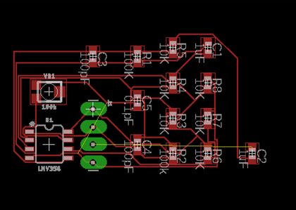
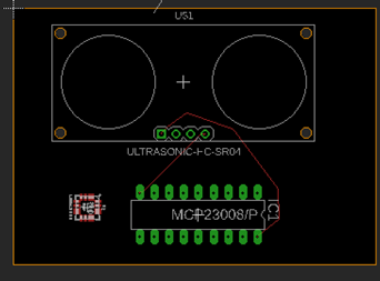
Custom PCB
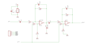
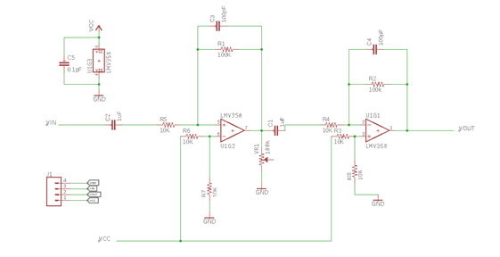
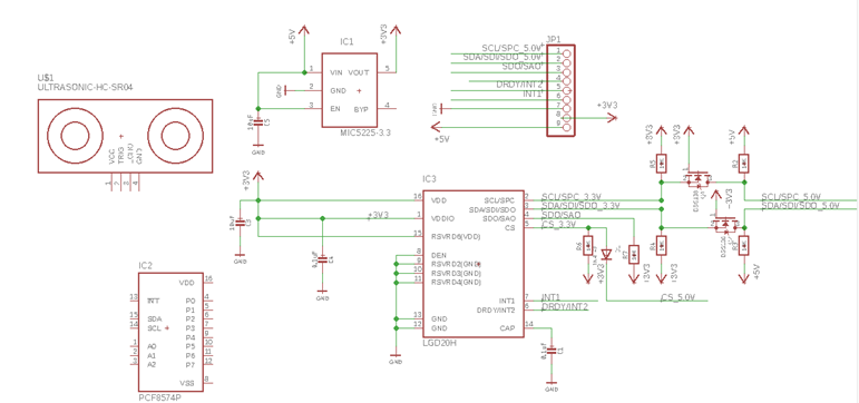
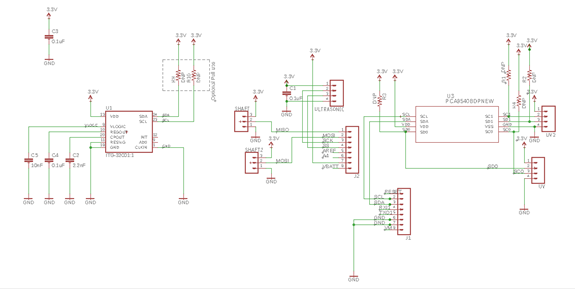
Figure 19: Eagle Schemtic
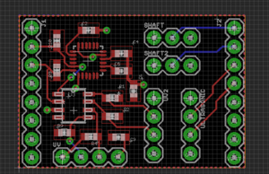
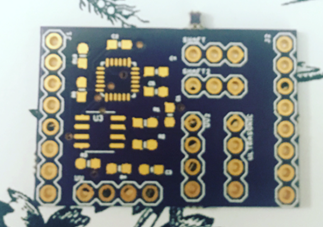
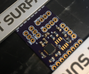
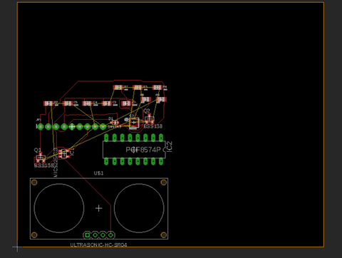
Figure 20: Finalized and approved board
For the AT-ST project, one of our goals is to create custom PCB using Eagle software. This software allows the user to generate PCB layouts, in order to use the Eagle software, I need to learn how to use the software. With lack of experience using the Eagle software previously, it took me a week to two weeks to learn the general concept. So the overview of the concepts is learning a PCB, also it is most common named “printed wiring board” or “printed wiring cards”. So it is a board that has lines and pads that connect various points together.
To Read More: https://www.arxterra.com/at-st-custom-pcb-layout-design/
Final Assembly
The custom PCB is for us to use less wire and clean and neat as possible and this the example of the small custom PCB made and manufactured by osh park. In this PCB has 13 surface mount component and seven through-hole parts l integration and testing of it. Customer wants us to build the PCB and implemented and integrated into the three-dot board, which is another custom PCB (microcontroller). From that Created the design in eagle software and had him to review it for approval.
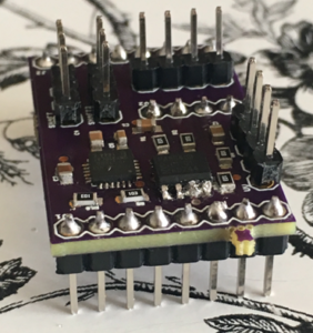
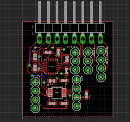
Figure 21, PCB with all components on.
To Read More: https://www.arxterra.com/spring-2018-at-st-assembly-of-custom-pcb/
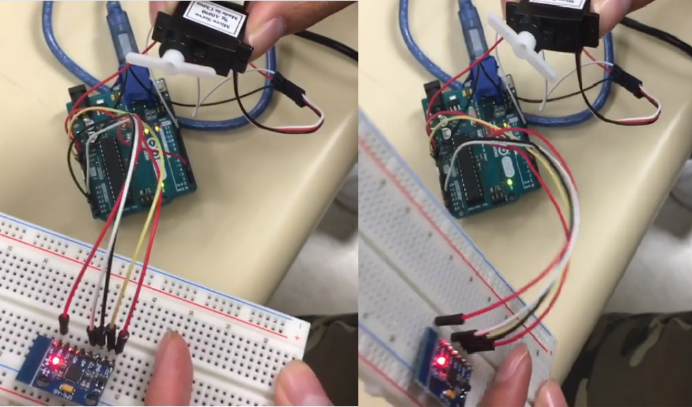
Fritzing Diagram

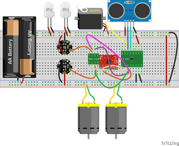
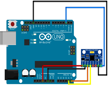
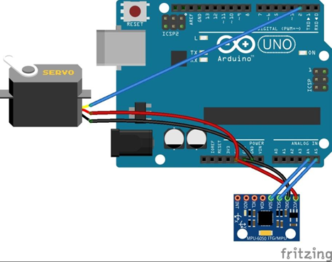
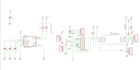
Figure 22: Fritzing Diagram
In this Figure 22, we have the 3-dot board, gyroscope, i2cexpander, two UV sensors, two IR leds, Servo, Ultrasonic, two motors, but actual we are using the micrometer with shaft encoder and 3 volts.
Old Fritzing Diagram: Preliminary Blog will be linked when published
To Read More: https://www.arxterra.com/spring-2018-at-st-fritzing-diagram/
Software
By: Samuel Yoo (Electronics and Controls – Software)
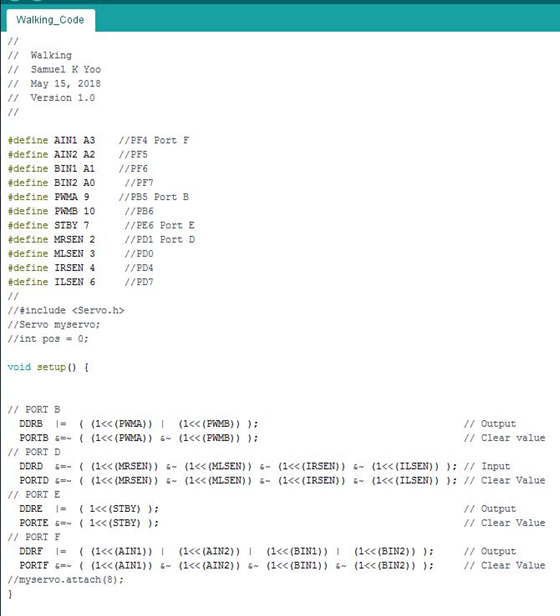
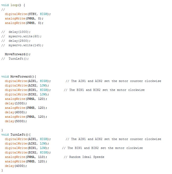
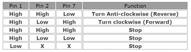
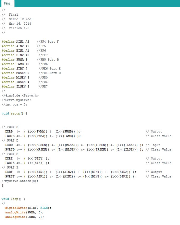
Walk Code
During the creation of AT-ST, this is a program that allows AT-ST to walk. Note that this program is used for the current model and might need to be updated later on. The code is very straightforward as it only uses the motor and control the speed. There are commented code for the servo to make it shift the bots weight.
To Read More: https://www.arxterra.com/spring-2018-at-st-walk-code/
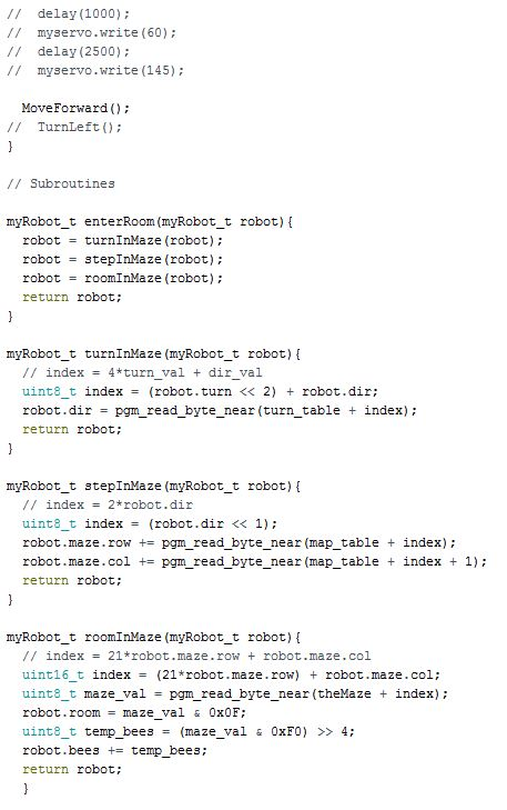
Whichway Code
In this code we are creating a which way sub routine. There are two methods of doing this code one which is the switch case decision. The other method is the index method which saves a huge amount of coding. The method used for the AT-ST is the index method.
To Read More: https://www.arxterra.com/spring-2018-at-st-which-way/
Line Following
For the robot to follow a line there must be two sensors in front of the robot. These sensors must be left and right of the line. The first reading from the sensor should be white or zero because it does not touch the line. Once the sensor touches the line the robot should move away from the line.
To Read More: https://www.arxterra.com/at-st-line-follower-code/
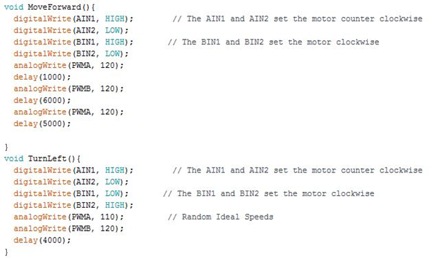
Turning
The turning part of the code relies only on the motor speed and direction. One of the motor speed has to be lower for the bot to turn. The turn is a bit wide however it will turn in the direction of the leg that slow down. The direction could also allow a pivot turn which in that case the motor must go the same direction.
To Read More: https://www.arxterra.com/at-st-turning-code/
Servo Control
The servo is controlled is set on a delay to move back and forth. This delay need to be in sync with the leg moving forward to replicate the Theo Jansen biped. There also need to be a heavy enough weight to move the center mass, however it can’t be too heavy to lose the balance of the biped.
Ultrasonic Sensor code
This code is helps detect objects in front of the robot. Once there something in front of the robot the code changes the path in the maze to avoid the object.
UV Sensor Code
The code here is to detect the line. The sensor also need a UV light, or any led that would result in finding the line. This led and sensor must be tested before line coding.
Shaft Encoder Code
This code allows the user to know where the shaft is located as the motor spins. The location of the shaft is important this can determine how robot would move forwards. With enough testing the values from the shaft encoder can have precise movement with correct speeds.
Custom Command Code for Arxterra
This code aids in controlling the robot movement through the app. Once the code on the app goes to the 3 dot board it would be able move.
Final Code & Calibration
At the end of the day the robot should be able to walk through a maze without falling down. It should be able to turn and detect robots in front of it. The motors might need to be set on differents speed to move straight because they are different.
To Read More: https://www.arxterra.com/spring-2018-at-st-final-code/
Verification Plan
By: Joseph Cho (Mission, Systems, and Testing)
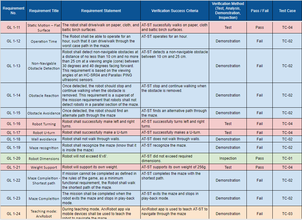
Verification test plan is used to verify our L1 and L2 requirements through analysis, inspection, demonstration, and/or testing. The L1 and L2 requirements are listed in the spreadsheet below. The test plans will be generated from the spreadsheet. Few of L1 and L2 requirements have been reworded by MST.
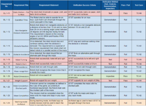
Figure 24: Verification Test Matrix Continued
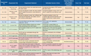
Figure 25: Verification Test Matrix Continued
To Read More: https://www.arxterra.com/at-st-verification-test-plan/
AT-ST Verification Matrix and Test Plans: https://docs.google.com/spreadsheets/d/1HHaQliwvLYbqErqJi2AVOlqGEzNX7grKOYJ2CBUFQ7M/edit#gid=0
AT-ST L1 and L2 requirements:
https://docs.google.com/document/d/1xd6XmBhFJmCM-EjkpJS05NfXEHCaKcGz9SlAz1I7_4M/edit?usp=sharing
AT-ST Set and User Guide
By Intiser Kabir (Project Manager)
Assembly
The assembly of the robot take around an hour to physically build the kit. First part that need to be created are the two legs. Then the next step is to get the shaft for each legs. After finishing the legs connect the whole body together and connect the pieces from the leg to the shaft.The electronics connection on the other hand will take less than a few minutes, as they have ribbon cables.
Project Documentation
Project Manager Resources
Project Burndown: https://docs.google.com/spreadsheets/d/1BA9CalRxpTEMkaj8f5vmxWCxLu6S8eY3skgKfgoj3_0/edit?usp=sharing
Project Task Matrix: https://docs.google.com/spreadsheets/d/1tRwaMMoftwmn_mTPSmE4tkiAcbTXb15QuQ_Iaq3tRSA/edit?usp=sharing
Project Gnatt Chart: https://docs.google.com/spreadsheets/d/1qJi5Dn5vKa3LCvSwmjcABUZHhiHcZaAdZUwo20mh_dQ/edit?usp=sharing
Work Breakdown Structure: https://drive.google.com/file/d/1kZrGJFDMnC0kTgMegdcvJuCHic7w2qYE/view?usp=sharing
WBS Blog: https://www.arxterra.com/spring-2018-at-st-work-breakdown-structure-wbs/
Creative Solution: https://docs.google.com/presentation/d/15-R1zJiGFsAFutUOhRmU5uyTVYaGsuqz92BFf58_nCg/edit?usp=sharing
Project Preliminary Budget: https://docs.google.com/spreadsheets/d/1oxZsYJLEbIrbdFIPajqWeOOjfz4Kuyb-HZ5zrYufdqY/edit?usp=sharing
AT-ST PDR Presentation: https://docs.google.com/presentation/d/1-NQhuu86UMHXlMK_8aWX3uDd6Hr-O2HtnjHZ4MrP_hY/edit?usp=sharing
AT-ST PDR Blog: Linked when Published
Weekly Meetings: https://drive.google.com/drive/folders/1gVZSaHw7cnSAfjJnVRijB9rwGvk1QtHc?usp=sharing
E&C Resources
PCB & Fritzing Diagrams: final PCB and Fritizing, link if broke: https://drive.google.com/file/d/1JSqOuvCCSRSwIWFCpZrfkfj4Ga_RjFsW/view?usp=sharing
AT-ST Arduino Codes: Code-20180517T100914Z-001, link if broke: https://drive.google.com/drive/folders/1DZBI-riP9-Pr2yBkuRpEFd-wREy2lyig?usp=sharing
MST Resources
System Block Diagram: https://drive.google.com/file/d/1j5_l9pjMIDLRvQ1kjKGN6JH-4fDHt6XK/view?usp=sharing
SBD Blog: https://www.arxterra.com/at-st-system-block-diagram/
Project Breakdown Structure: https://drive.google.com/file/d/1TlbJeORAzsJNmbRW44lwExin888p_u7W/view?usp=sharing
PBS Blog: https://www.arxterra.com/at-st-product-breakdown-structure-pbs/
Resource Report: https://drive.google.com/drive/folders/1zvRPpSIN7W8F0zzLFqQXKC7xtbaw7mvQ?usp=sharing
Power Budget: https://docs.google.com/spreadsheets/d/1OaWtFrqYVQsylEh2nXOvKjFT-g2KG72ej-pF6OJWQ54/edit?usp=sharing
Mass Report: https://docs.google.com/spreadsheets/d/1_q0K2hwcqDshcp3e7MT1azD3lbXh80qJeSJ1bALZQZ0/edit?usp=sharing
Interface Matrix: https://docs.google.com/spreadsheets/d/1BBBQAYeuzqONEjrJYas0pvlGR3igG8wluO_shYIF2mE/edit?usp=sharing
AT-ST Command and Telemetry (Mobile App.) Blog: https://www.arxterra.com/at-st-command-and-telemetry-mobile-app/
Verification Matrix: https://docs.google.com/spreadsheets/d/1HHaQliwvLYbqErqJi2AVOlqGEzNX7grKOYJ2CBUFQ7M/edit?usp=sharing
Manufacturing Resources
Final Solidworks Model: Solidworks files-20180517T101958Z-001, Link if Broken: https://drive.google.com/drive/folders/1NlfKwoVS82mzJICGQdZJKbr_0ODFaeZI?usp=sharing
Lessons Learned
By: Intiser Kabir (Project Manager)
From this class. The most important thing I learn is time management and trying to find different ways of communicating with the group to get everyone together. One of the most Critical things to do is Planning and Scheduling, even then a lot of things don’t go to plan as one may expect.
- Things Don’t Always Go Into Plan! Whenever you are scheduling meetings with your group, make sure to have a back-up plan. Especially since there are members that aren’t available on certain days and sometimes you or someone in the group will get sick. Always have some to plan around those situation.
- Communication. One of the biggest issues I have faced as my time as Project Manager is certain members not informing issues they have, I recommend finding a way with such member that like voice chat on Discord or calling them up. Is best to know when they are free so you can talk them individually to see what issues they are having and see what can you do to help out.
- Research. At the very beginning, do a lot of research on previous projects see why they fail, and see their advice on how to improve it. Do research on the parts you may buy. For us we had to buy specific type of Male to Male pins and had to custom make our housing just to connect the Shaft Encoder. If we never knew this a long time ago, we wouldn’t have as much issues regarding the Shafts.
- Always Get Customer’s Approval. I myself learned this the hard way. For our preliminary design our Customer didn’t like the fact we were using servos to move our leg and especially wanted us to use motors. We had to go back into the drawing board at a crucial point of our project. The customer was generous enough to help and advice us on how to improve our project or what we should look into while doing our project. Don’t be afraid to approach him when you are facing issues.
- Get a Prototype working ASAP. The Customer made a huge point on it especially before Spring break to get a working model ready. The long you hold off on that the harder it will take to get your project up and ready. You will find out issues a lot faster the quicker you make your prototype. Especially since you don’t have much time to begin with in class to work on such a massive project.
- Plan to iterate the 3D model at least 5 times and don’t rely heavily on the 3D printing for some parts, find alternatives and don’t rely on one company for your prints. There are many parts that need to consistently be changes there will always be issues regarding 3D printing such deformation or parts come out too fragile. Find alternative ways to make certain parts like model injects. Research on how to do that!
- PCB is Not Easy to Make. It took my E&C any different iterations to finally get approved. Assembling is the hard part of making a PCB. Please remember the quicker you quicker you can make your PCB the more money you can save. Also try to Remind your Customer you have more than 1 custom PCB so he doesn’t just focus on 1 and never check the other ones.
- Provide Weekly Goals. To keep your project on task, see what each person has to do per task so they can work independently. Planning isn’t easy but, but as Project Manager just form a general goal and see how everyone is doing.
- DON’T RELY ON 1 PERSON TO DO ALL THE WORK. There are some points where my E&C Software had to build and test by himself. Please don’t let this happen, make sure everyone do their part because you can’t let someone do all the work.
This class went fast and you will realize how important time is. Is hard to take breaks at time for this class. Plan accordingly, help each other, learn from your mistakes, and most importantly get in your Customer’s good side. You want the Project succeed as much as you can. Don’t wait to the last minute to get everything ready always have back up, 1 of our motors failed in the last minute which ended up hindering us. So having multiple replacements isn’t a bad thing!
Future Improvements
- Find alternative ways on making some of the parts and don’t rely heavily on 3D Printing. Somethings aren’t designed to be 3D Printed!
- Research on how to code Shaft Encoders.
- Look into current regulators to prevent your motors draining out.
- Find a way to control the balance of the the AT-ST so it doesn’t wobbles as it walks.
- Look into getting a boost converter to give more voltage out for the motors.
- Redesign leg components into simple connector shapes that work with screws to make 3D printing easier and more accurate.
- Create panels to cover gaps in the model to hide wires and to make the robot more stable. Also to make the robot look cooler.
- Implement more holes in the design for screws so that the holes are in the correct exact locations of the model and so that the screw holes in the model are easy to access.
Project Video
–Linked When Made–