Spring 2018 AT-ST Command and Telemetry (Mobile App.)

By: Joseph Cho (Mission, Systems, and Testing)

Verified By: Intiser Kabir (Project Manager)

Approved By: Miguel Garcia (Quality Assurance)


Table of Contents

Introduction

The AT-ST will be remotely controlled using an Android or Apple mobile device with Bluetooth connection. Once requested to the Arxterra, there will be a mobile app available to download. Using the mobile app, ArxRobot, you will be able to create custom command and telemetry for the connected robot. The mobile device will be connecting with the 3DoT board via Bluetooth. “User” or the person controlling the mobile app will be able to control the prototype robots with their commands.

Main screen of ArxRobot app

Figure 1: Screenshot of the Arxterra App

Description:
On the main screen, you will only see the up-down controls when you first launch the app. The app is currently modified to fit the AT-ST remote controlling. There is a D-pad (directional pad) to control the movements, four selected for the different phases, and one boolean for the run.

Definition

Movement is referring to the AT-ST moving forward, turning left, and turning right. Each command is activated by pressing up, left, and right respectively on the D-pad.

Phases are referring to different stages that AT-ST will go through. “Select” is a command type that returns which phase the user selected back to the 3DoT board to be processed. “Sleep” is a phase that the AT-ST will be resting and wait for further commands. “Learning” is a phase that the AT-ST should navigate through the maze following the user’s command and recording those commands. “Shortest path” is a phase that the AT-ST should navigate the predefined shortest path through the maze. “User define path” is a phase that the AT-ST should navigate the learned user-defined path.

“Boolean” is a command type that returns OFF or ON (false or true) based on the user’s input. The “run” boolean will only affect the “shortest path” and “user-defined path” phases. AT-ST will start moving on its own if “run” is ON and in phases “shortest path” or “user-defined path”.

Flowchart of Arxterra app

Figure 2: Flowchart explaining the how the App works

Description:

The “select” will determine the four phases: Rest, Learning, Shortest Path, or User Defined Path. Based on the phase, AT-ST will act out the following. At “Rest”, AT-ST will do nothing. Durning “Learning” phase, AT-ST will move according to the User’s command and record the movements to learned user-defined path. In “shortest path” phase, AT-ST shall navigate the predefined shortest path only if “Run” is ON. Similarly, in “User Defined Path” phase, AT-ST should navigate the newly learned user-defined path only if “Run” is ON.

Addresses of each command

Figure 3: Screenshot of the Arxterra App that shows trace

Description:
When show trace and trace is on, the address of each custom command can be seen. The list of commands and their address will be shown below.

Custom commands and Addresses

Figure 4: Custom Commands and Addresses

Reference

  1. https://www.arxterra.com/getting-started-with-arxterra/
  2. https://www.arxterra.com/goliath-fall-2017-app-setup-and-remote-control-user-guide/

Spring 2018 AT-ST 3D Print Time

By: Joseph Cho (Mission, Systems, and Testing) And Danny Pham (Manufacturing)

Verified By: Initiser Kabir (Project Manager)

Approved By: Miguel Garcia (Quality Assurance)


Table of Contents

Introduction

This blog post will estimate the time taken for the 3D printing of AT-ST. Our current design is not finalized and will see changes in the near future. With this estimate, our project cost will be more accurately calculated and plans may change to align with the schedule.

Design diagrams

Theo Jansen Leg

Figure 1: Theo Jansen Leg measurements

Description:

The Theo Jansen legs will be 3D printed and made with ABS(Acrylonitrile Butadiene Styrene). Most of these measurements are scaled numbers from the design of the actual Theo Jansen legs. The width/thickness was taken from measuring the previous semester Velociraptor project. There is a slight difference between the width and thickness. Also a thickness of 3.1mm for carbon fiber is thick and efficient enough to support the structure of the legs while saving money. Velociraptor of Spring 2017 had thickness of 3.175 mm, but their design had bigger and heavier parts loaded on to the legs. The main parts to print for the body will be the 4x3x2.5” box, side panels, and some gears.

Figure 2: Makerbot Print Program Diagram

We will be using the Makerbot Print program with the settings below to calculate the print time.

Calculations

(0.5mm nozzle, 50mm/s, 0.2mm layer height, 20% fill) 

Figure 3: Estimate of 3D printing using MakerBot

Description:

According to the Replicator 2 3D printer, it will take 16h and 35 minutes to print our robot. This fails the level one requirement of maximum print time for a single part to be two hours and the total print time for the robot to be less than six hours. The box body is the biggest part of the robot so it will take the longest time to print. In order to fulfill our level one requirement, we should adjust the size and dimensions of the body. The components for each leg piece are already thin and quick to print.

Actual Print Time

Figure 4: Print times

Description:

The Actual print time without the laser printable parts was 5 hours and 56 minutes. This is within the 6 hour project allocation for the 3D printing time.

Reference

  1. http://www.protechcomposites.com/standard-thicknesses/
  2. http://www.makexyz.com/f/estimating-print-time-7ae2fe0cb09b3a8ca4e080a52c66e0b0
  3. https://www.arxterra.com/simulation-and-experiment-of-3d-printing/
  4. https://docs.google.com/spreadsheets/d/180lRo-Qa5YwvbPFjHR9tjkG2ByO9Ti5M52t809bQhYo/edit

Spring 2018 AT-ST Sensor Testing

By: Shweta Hebbalkar (Electronics and Control – Hardware)

Verified By: Intiser Kabir (Project Manager)

Approved By: Miguel Garcia (Quality Assurance)

Table of Contents

Ultrasonic sensor – HC-SR04

Introduction

As the name implies this device uses an ultrasonic sound to measure the distance between itself and the nearest solid object. Like if we take the nature’s example then it would be like Bats detecting shapes from the sound. So with this key feature has become a staple in our projects because the last thing we want is for our project AT-ST to get the pushed out from the other robots.

Features

  • Operating Voltage: 5V DC 
  • VCC  = 5 volt power connection
  • Operating Current: 15mA
  • TRIG = trigger pin (input) 
  • Measure Angle: 15°
  • ECHO = Echo pin (output)
  • Ranging Distance: 2cm
  • 4m – GND = Ground

Theoretical Explanation of the ultrasonic sensor

Let’s look in more depth of this ultrasonic sensor so for our project we are using the HC-SR04 and it consists of two ultrasonic transducers one is used as the transmitter and another one is used as a receiver. Now when we normally operate the transmitter sends out a series of ultrasonic pulses remember the receiver despite its proximity does not pick up these pulses because ultrasonic signals are very directional. However, if an object in front of the device it will reflect the signals back to the receiver. The time delay that takes from the transmission and receiving the signal is used to calculate the distance so, for example, a longer delay will be considered as long distance and the shorter time delay will be the shorter distance. Now if we send the 5-volt, 10-microsecond pulse to the device then transmits 8 ultrasonic pulses either at the 40-kilohertz each. The echo pin will output a pulse between 100 and 50 – microsecond to 25 milliseconds and that pulse width is used to calculate the distance it will output a pulse of 38 milliseconds if there is no object detected.

Calculating the distance

To determine the distance ultrasonic signal travel at the speed of sound at 20 degrees Celsius the speed of sounds is 343 meters per second now remember the time we’re measuring with the HC-sr04 is for return trip so we’ll need to divide this in half to calculate the actual distance.

∆t=time delay

c=speed of sound (cm)

D=Distance Measured

D=∆t2*c  

As an example

D= (500/2) * 0.0343 = 8.575 cm
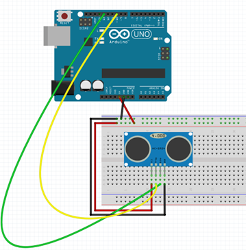
Experiment

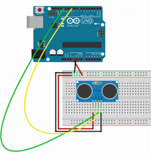
Figure 1: Fritzing diagram with the Ultrasonic Sensor.
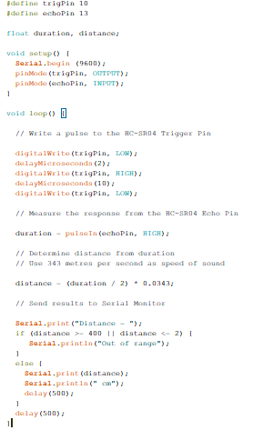
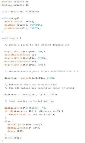
Code

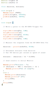
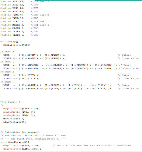
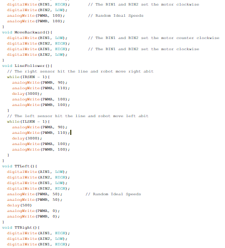
Figure 2: Screenshot of the code
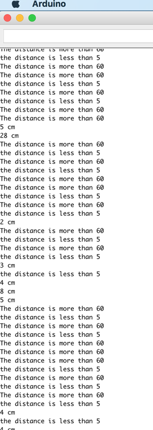
Output

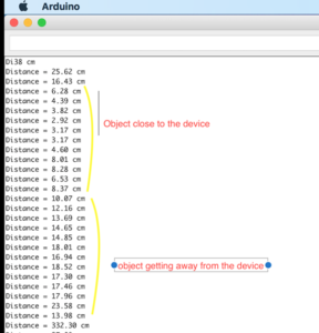
Figure 3: Data from Arduino

Servo – Ultrasonic #1

Introduction

Servos are combined with the motor and also control electronics; this combination makes an easy to use package. The PWM signals with a periodic time of 20 milliseconds and a duty cycle of one to two milliseconds so five to ten percent. While an on time of one millisecond resents the -90-degree position of the motor shafts. 0-degree positions and the 2 milliseconds the +90-degree position. So we can rotate the shaft a total of 180 degrees. 

Features

  • Voltage: 4.8~6.0V
  • Torque: 3.5kg.cm@4.8V, 4.8kg.cm@6.0V
  • Speed: 0.17/60ТА @4.8V;0. 14/60ТА @6.0V
  • Size: 38.6×18.8×34.9mm
  • Wight: 37 g
  • Use Angle: <=160ТА

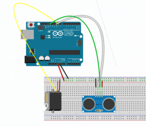
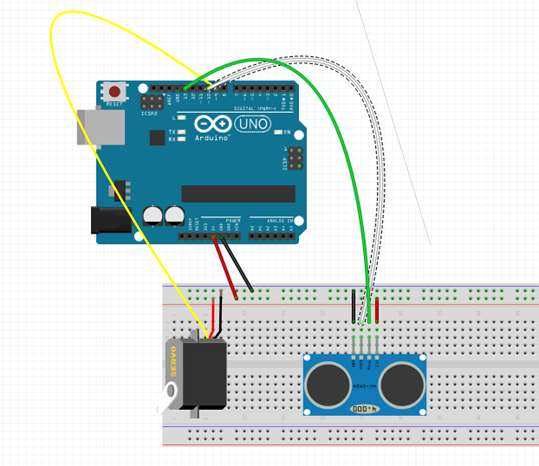
Figure 4: Fritzing diagram

Code


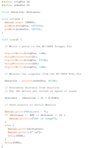
Figure 5: Screenshot of code

Output

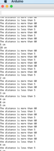
Figure 6: Arduino output

Servo – Ultrasonic #2

Introduction

In this experiment, I created an object detector. So this module will scan from 0 to 180 degrees, and once its finish scanning the module will point at the object. If I displace the object, then the module will scan again from 0 to 180 degrees and trying to look for an object. This is one of the ideas for our project trying to avoid the other robots from the maze.
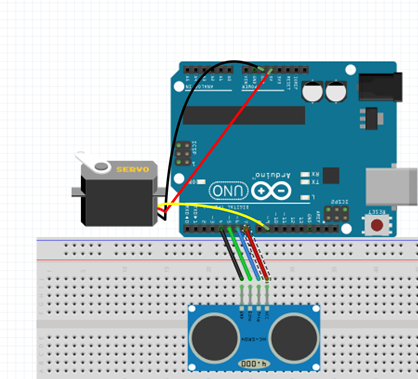
Fritzing diagram

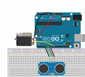
Figure 7: Fritzing Diagram showing Servo and Ultrasonic
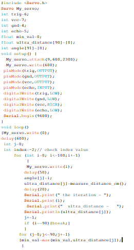
Code


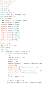
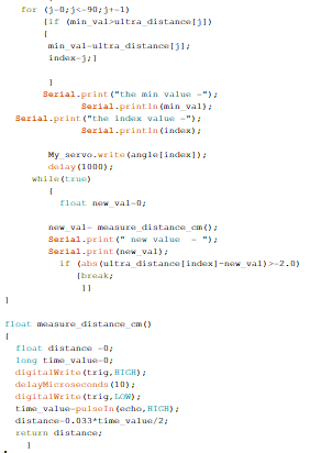
Figure 8: Screenshot of code

Figure 9: Screenshot of code cont.

Output

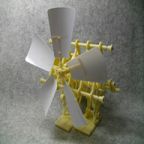
Figure 10: Physical Demo of Servo and Ultrasonic

RGB led  

Introduction

Formerly, we were going integrate the color sensor to our robot. In order to require the decision either to take right, left, or keep going forward. Now, the color sensor is not required for our project because we change our maze requirements. But before that, I am going to explain the RGB Led to help me understand the color sensor little better. So, an RGB LED is a three LED’s in one basically 4 LED. This is a basic experiment to learn new circuit components and new programming skills.

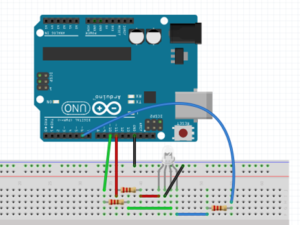
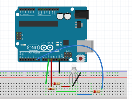
Figure 11: RGB light connections on using fritzing diagram

Code

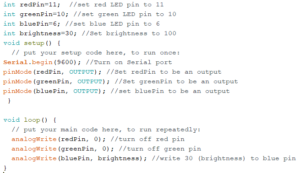
Figure 12: Screenshot of code

Output

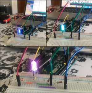
Figure 13: The RCB displaying 3 different colors
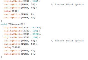
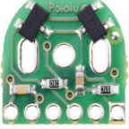
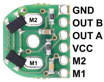
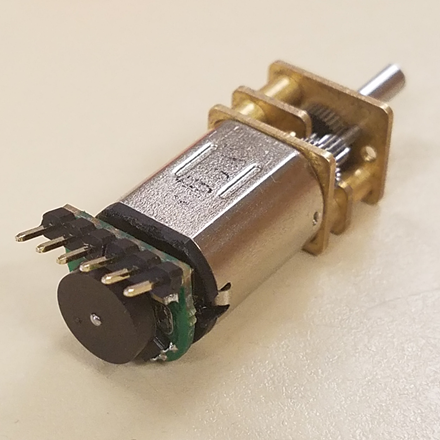
Dc Motor

DC Motors that operate on direct current as opposed to motors, which operate on alternating current. We are using the small dc Motors for our project in order to move let’s look into how dc motor works. The shaft of the motor, the part that rotates is referred to an armature. On the armature, there are coils of wire these coils are connected to the commutator. The connections to the commutator are called the brushes, where the positive and negative voltage is applied. On the outside of the motor, there is a permanent magnet arranged in opposite magnetic polarity, now when dc current is applied to the commutator it sets up a magnetic field inside the coil. The coil magnets interact with permanent magnets causing the armature to rotate, now as the armature rotates the polarity is continually reversed generating the magnetic field to be reversed and the rotations to continue.

A motor driver module helps the dc motor with an Arduino, which means that dc motor will get the more current in order to, work, in other words, a current amplifier. So a motor driver is a breakout board, which consists of an L293D IC, the main purpose of the motor driver is to take a low current signal and convert it to a high current signal.

Conclusion

Due to some feedback from the Professor, we are not using RGB and will be using UV sensors with IR LEDs. We are using Ultrasonic as an avoidance mechanism. The DC motor is used to move our legs. We are planning to use servos to help control the center of gravity.

Reference

  1. https://cdn.sparkfun.com/datasheets/Sensors/Proximity/HCSR04.pdf
  2. https://www.sainsmart.com/products/ultrasonic-ranging-detector-mod-hc-sr04-distance-sensor
  3. https://components101.com/ultrasonic-sensor-working-pinout-datasheet
  4. https://www.radioshack.com/products/radioshack-standard-servo
  5. https://www.sparkfun.com/datasheets/Components/YSL-R596CR3G4B5C-C10.pdf
  6. https://nationalmaglab.org/education/magnet-academy/watch-play/interactive/dc-motor

Spring 2018 AT-ST Preliminary Model

By: Danny Pham (Manufacturing Engineer)

Verified By: Intiser Kabir (Project Manager)

Approved By: Miguel Garcia (Quality Assurance)

Table of Contents

Introduction

Our initial design included a similar concept to the Titrus III robot that involved moving the robot with servos. Since this was not ideal, we redesigned the legs to move using dc motor instead of servos and keeping the servo as a weight shift mechanism. Our design was inspired by previous velociraptor projects and an actual biped walking Theo Jansen kit.

Initial Model

For our new design, we switched from a Titrus III leg design to the Theo Jansen design. We went with the Theo Jansen design because this design works much better when it is connected to a motor and the leg can rotate in a continuous motion.

Figure 1: Theo Jansen Leg model

Description

This is the Theo Jansen design. It incorporates a motor that rotates a gear that in turn rotates a shaft connected to the leg. This will rotate the rest of the leg and create a circular walking motion for the foot. This will allow the robot to take a step.

Figure 2: Preliminary Model

Description

This is our first model that incorporated the Theo Jansen legs and split leg mechanism. I used a box for the body and implemented door hinges on the side that would act as the split leg mechanism that turns the legs. There are servos inside the box that are connected to these panels, and the servos would move the panel in and out to turn the legs. The DC motors are planted on the other side of the panels inside the box, and the motor is connected directly to the Theo Jansen leg. The motor rotates the leg and creates the walking motion for the robot.

Figure 3: Side views of Preliminary Model

Issues with the model

Some issues with the model include the distance between the legs and center of mass. Because the legs are so far apart, it makes it much more difficult to balance the center of mass when the servos are turning the legs. If we had the legs closer, the weight is closer to the center instead of the sides and it will be easier to balance the robot. The box body takes too long to print and exceeds our requirement of six hours. Also, there are issues with the foot design, and how it plants itself on the ground when it is moving in circular motion. Because it is moving in a circular motion, the foot cannot be static or else it will not stay in parallel with the ground and that will cause points of contact that will conflict with the walking motion. The previous velociraptor group used springs in order to allow the foot to move in parallel with the ground, but it was not stable and made balancing the robot harder.

Conclusion

Our new design incorporates DC motors to move the legs. We will incorporate a weight shifting mechanism in the future with a servo so that we can do robot balancing during walk motion, but for now, the servos are used to turn the legs. A future modification of the design may include less distance between the legs so that we can balance it easier and a smaller mass for the body so that we can fulfill the print time requirement.

Spring 2018 AT-ST Mechanical Drawings

By: Danny Pham (Design and Manufacturing Engineer)

Verified By: Intiser Kabir (Project Manager)

Approved By: Miguel Garcia (Quality Assurance)

Introduction

For our robot to walk and turn successfully, we will be designing elements of the robot that will be able to balance itself and move smoothly. The AT-ST walker design will incorporate parts of the Velociraptor and Biped design from previous semesters. The AT-ST will also incorporate dc motors instead of servos, so we switched out from our previous Titrus III leg design. In our case, our robot designs will be using the Theo Jansen leg design and split leg function that the previous 2017 Spring velociraptor project used.


Concept Sketches

Figure 1: initial sketches and idea of Priliminary Model

Description

For the body of the AT-ST walker, for preliminary design, we will be using a box. The box will have side panels that open and close like a door. The Theo Jansen legs will be attached to the outside of the panel, and the motor will be mounted on the inside of the side panels to connect to the legs. Another set of gears and servos inside the body will move the connector to open and close the doors, which in turn will turn the leg like split leg function.

Figure 2: initial ideal measurement of our Theo Jansen Leg

Description

This is the Theo Jansen leg design. The measurements are taken from the actual Theo Jansen leg dimensions. The width that we picked for the leg is 3.175mm because it will be made of carbon fiber and that width is sturdy enough for the carbon fiber material to support the leg.

Figure 3: 2D Sketch of Theo Jansen Legs

Description

The leg is structured so that it is not just a one dimensional build of the leg. Each component is doubled so that the leg structure is wider and that will make the leg more stable. The previous velociraptor group also included springs on the feet in order for the foot to not be parallel to the ground at all times. This will help the Theo Jansen leg motion and keep it moving.

Figure 4: Measurement Parts

Description

These are the individual measurements of each connector in the legs, and other miscellaneous parts in the body.

Conclusion

These will be the basic design of the AT-ST walker robot. The measurements used for the leg design are scaled versions of the actual model and models from the previous semesters to fit our maze and robot definitions. The measurements and shapes are subject to change once we test the function of a rapid prototype of the robot design.

Spring 2018 AT-ST Product Breakdown Structure (PBS)

By: Joseph Cho (Mission, Systems, and Testing)

Verified By: Initiser Kabir (Project Manager)

Approved By: Miguel Garcia (Quality Assurance)


Introduction

The product breakdown structure below visually presents the products that will be created based on the assignments. The product breakdown structure should reflect the work breakdown structure created beforehand.

Figure 1: AT-ST Product Breakdown Structure

Description

The PBS (Product Breakdown Structure) is showing the different productions by each division. E&C (Hardware) division will be making a custom PCB shield for the sensors and gyroscope. E&C (software) division will be programming codes for movement and sensory data. Manufacturing division will be prototyping models for the body and legs of AT-ST. MST division will be customizing Arxterra control panel to have suitable commands and telemetry for AT-ST.

Reference

  1. https://www.arxterra.com/fall-2017-velociraptor-preliminary-design-document/

Spring 2018 AT-ST Turning Code

By: Samuel K Yoo (Electronics & Control – Software)

Verified By: Intiser Kabit (Project Manager)

Approved By: Miguel Garcia (Quality Assurance)

Table of Contents

Introduction

The objective is to focus on the different methods of turning for the robot. The first method is timing turning which tells the robot to turn for a certain amount of time. The other is an infinite state machine which uses the outer sensors to tell the bot which state it is in. This turning sequence used for the robot has wheels, which the AT-ST does not. The concept of turning can be used for the AT-ST.  

Code

CHANGE CODE TO <code> type

Figure 1: Screenshot of code

Figure 2: Continuation of Screenshots of code

Figure 3: Last part of code screenshot

Explanation

The code, in the beginning, initializes certain variables and sets them as inputs and outputs. After this the code contains a line follower code which makes the robot follow the line. There are then the subroutines for the time turning. The subroutine near the end of the code allows the bot to make a left, right and turn around. Time turning is a method of spinning the wheels in the same rotation until it points in another direction.  Each turn must be tested to find the desired direction. The values in the code are placeholders until real values are obtained. This code however only works with motors, not servos and needs to be updated at a later date. The finite state machine code is not in the list above, however, I can explain the logic and some pseudocode.

The logic behind the finite state machine is to switch from one state to another state. These states will tell the robot it needs to continue, turn, or not until it reaches another state. If all sensors read black, it is at an intersection and will either start turning left right. Next, it would jump to the next state and see if the sensors outer sensor read the white part of the maze if so it would continue to turn until it sees all black. After that, it would proceed to move forward.

Conclusion

This whole entire blog post is to make the turning code. The time turning is in the code, however, it does not suit the AT-ST because of the difference in components. The finite state machine is not implemented yet. This post will require further updates for both the inclusion of the state machine turning and the servos.

Spring 2018 AT-ST Shaft Encoder

By: Joseph Cho (Mission, Systems, and Testing)

Verified By: Initiser Kabir (Project Manager)

Approved By: Miguel Garcia (Quality Assurance)

Table of Contents

Introduction

For our AT-ST project, the two motors on the legs have to be precise. In order to know the exact location of the turns, shaft encoders have to be added. The shaft encoders that have been chosen will be using a magnetic shaft encoder. The magnetic shaft encoder uses hall effect to determine the rotation of the axle.

Hall Effect

The shaft encoder is packaged with a 6 pole magnetic disk that is used to provide the magnetic field. Hall effect is observed when magnetic field causes the small current of elections to deviate and produce Hall voltage. When the magnetic disk rotates, it causes changes in magnetic fields. The hall effect latch (TLE4946-2K) inside the shaft encoder will sense these changes and output values. Using these output values, the position of the axle will be determined.


Connections on shaft encoder

Figure 1: Connections on shaft encoder

Description:

The shaft encoder has 6 pins. The M1 and M2 pins on the right are for powering the motor. The motor will be connected directly to the shaft encoder by soldering M1 and M2 holes in the center of the board. GND and VCC are used for powering the board. Output A and Output B are the outputs from the two TLE4946-2K hall effect latches.

After contacting the previous blog post author, the decision to use only one of the output has been made. The shaft encoder has two hall effect latches for accuracy and using only one of them is sufficient enough for our uses. A trade-off study may be done to test the amount of current used and the accuracy of the shaft encoder.

GearMotor with Shaft Encoder

Figure 2: GearMotor with Shaft Encoder

The image above shows that the shaft encoder is soldered onto the motor directly with male headers.

Schematic of Shaft Encoder

Figure 3: Schematic of Shaft Encoder

Description

The schematic shows the connections of the shaft encoder. The motor will be soldered onto M1 and M2 which will be powered by pin 1 and pin 2 of the shaft encoder. Pin 3 and pin 4 are used for Vcc and Ground. Pin 4 and pin 5 are outputs of the shaft encoder hall effect readings.

Reference

  1. https://www.pololu.com/product/3081/specs
  2. https://www.pololu.com/file/0J814/magnetic-encoder-kit-for-micro-metal-gearmotors-schematic.pdf
  3. https://www.pololu.com/file/0J815/TLE4946-2K.pdf
  4. https://www.arxterra.com/motor-shaft-encoder-trade-off-study/
  5. https://www.electronics-tutorials.ws/electromagnetism/hall-effect.html
  6. https://www.pololu.com/product/3081/specs#lightbox-picture0J6835;main-pictures

Spring 2018 AT-ST System Block Diagram

By: Joseph Cho (Mission, Systems, and Testing)

Verified By: Initiser Kabir (Project Manager)

Approved By: Miguel Garcia (Quality Assurance)

Table of Contents

Introduction

The system block diagram is made to visually show the systems of our product, AT-ST. The 3DoT board is the center of the system consisting the microprocessor and motor headers. There will be custom PCB that are connected to the 3DoT board for telemetry and sensors.

System Block Diagram

Figure 1: System Block Diagram


Description

The System block diagram above for AT-ST help visualize the system of the AT-ST.  The 3DoT board uses ATmega32U4 as the microcontroller. The 3DoT board consists of microcontroller, bluetooth transceiver,  servo header and dual motor driver. The 3DoT board (v6) will also be connected to the servos, motors and main custom PCB. PCB1 will be the master PCB that routes all input and output for the sensors. PCB 2 and PCB 3 are used for UV sensors which will be connected to the I2C expander on PCB 1. Bluetooth transceiver will connect to a mobile device using the Arxterra app via bluetooth.

I2C Expander

The UV sensors has to be connected to the I2C expander because the I2C address of same sensors will be overlapping. If we were to use a metaphor of I2C addresses, they are different phone numbers that are used to communicate. If two people were to have the same phone number, there would be a major problem. Signals may be overlapped, misguided, and destroyed when the addresses overlap each other.  The I2C address of the Si1145 (UV sensor) is set on 0x60, so I2C expander has to be used to change the single address into two different addresses. One thing to be cautious about is that the new address should not overlap the address of gyroscope (0x68 or 0x69).


References

  1. https://www.arxterra.com/fall-2017-velociraptor-preliminary-design-document/
  2. https://learn.adafruit.com/i2c-addresses/the-list