Fall 2015 MicroBiPed Prototypes

PROTOTPYE MILESTONES

By Railly Mateo (Systems Engineer)
Approved by Paul Oo (Project Manager)
Approved by Railly Mateo (Systems Engineer)

The video above shows the first step taken to understand the mechanics for how our Bipedal robot would walk. This model is considered our 1st Generation (1.0) of BiRex. It is a simply demonstration of a 5-axis leg using MG90S servos to rotate 2 axis, which then cause the rest of the leg to be displaced based on the angles of rotation. The commands used for this demonstration can be found in the Arxterra Application blog post.

This second video shows how we attempted to understand the coding for making our Bipedal robot walk. This model is considered our 2nd Generation (2.0) of BiRex. Although it has integrated 2 5-axis legs onto a body (wooden plank), this model lacked the feet needed to test stability.

This third video shows how we attempted to understand the motion for making our Bipedal robot walk. This model is considered our further developed 2nd Generation (2.5) of BiRex. As you can see, it has difficulty walking. This lack of balance comes from the fact that our legs cannot support overall stability alone, thus verifying the need to add the head and tail.
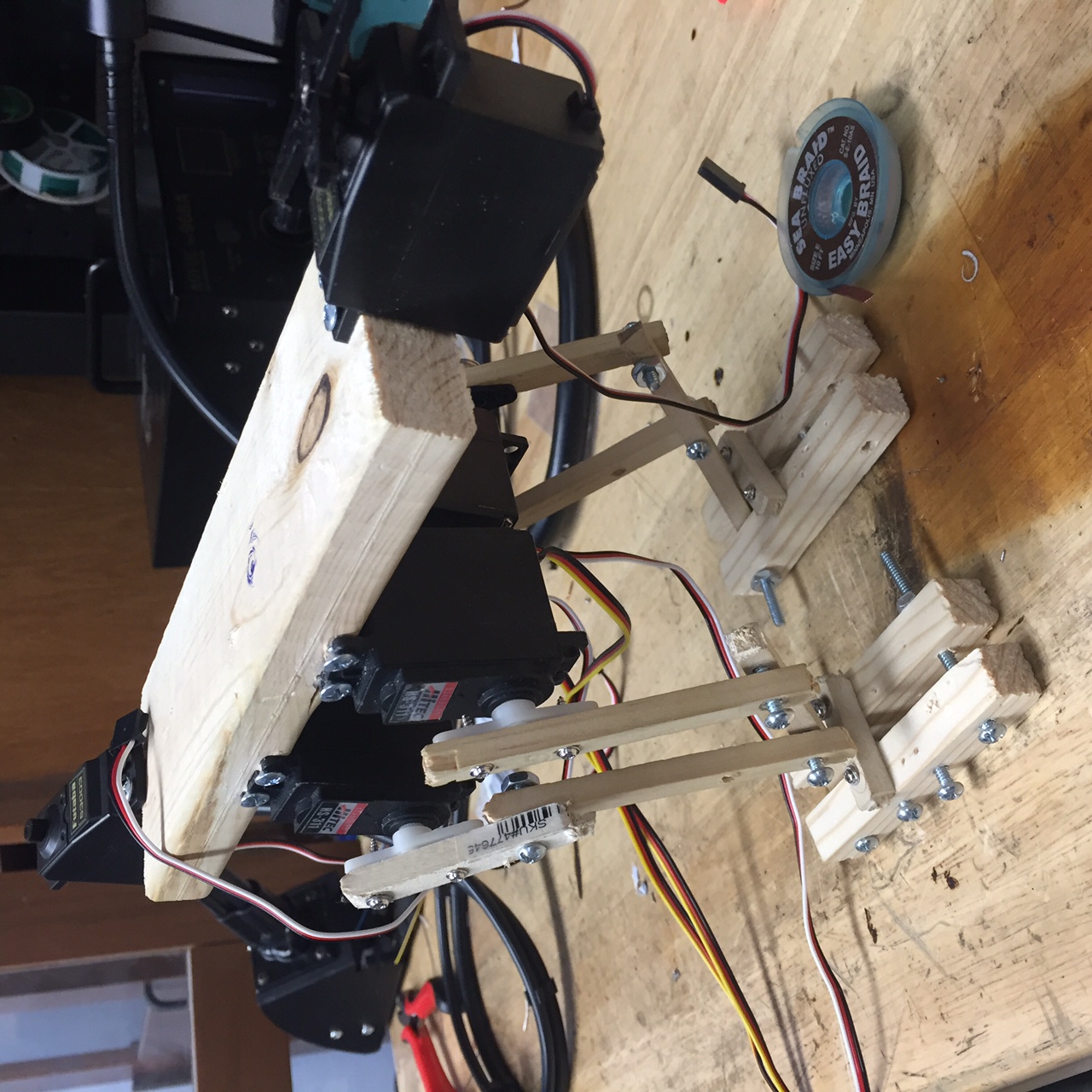
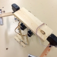
IMG_1852(1)

Image 1

The image above shows the inclusion of servos for head and tail. However, after showing the progress of our prototype to Professor Hill, he recognized the need to change the design of the leg. This model was unable to lift its leg up, but rather slid to go forward. Because of this detail, we were able to implement a more realistic prototype and find valuable feasibility information.

IMG_1853

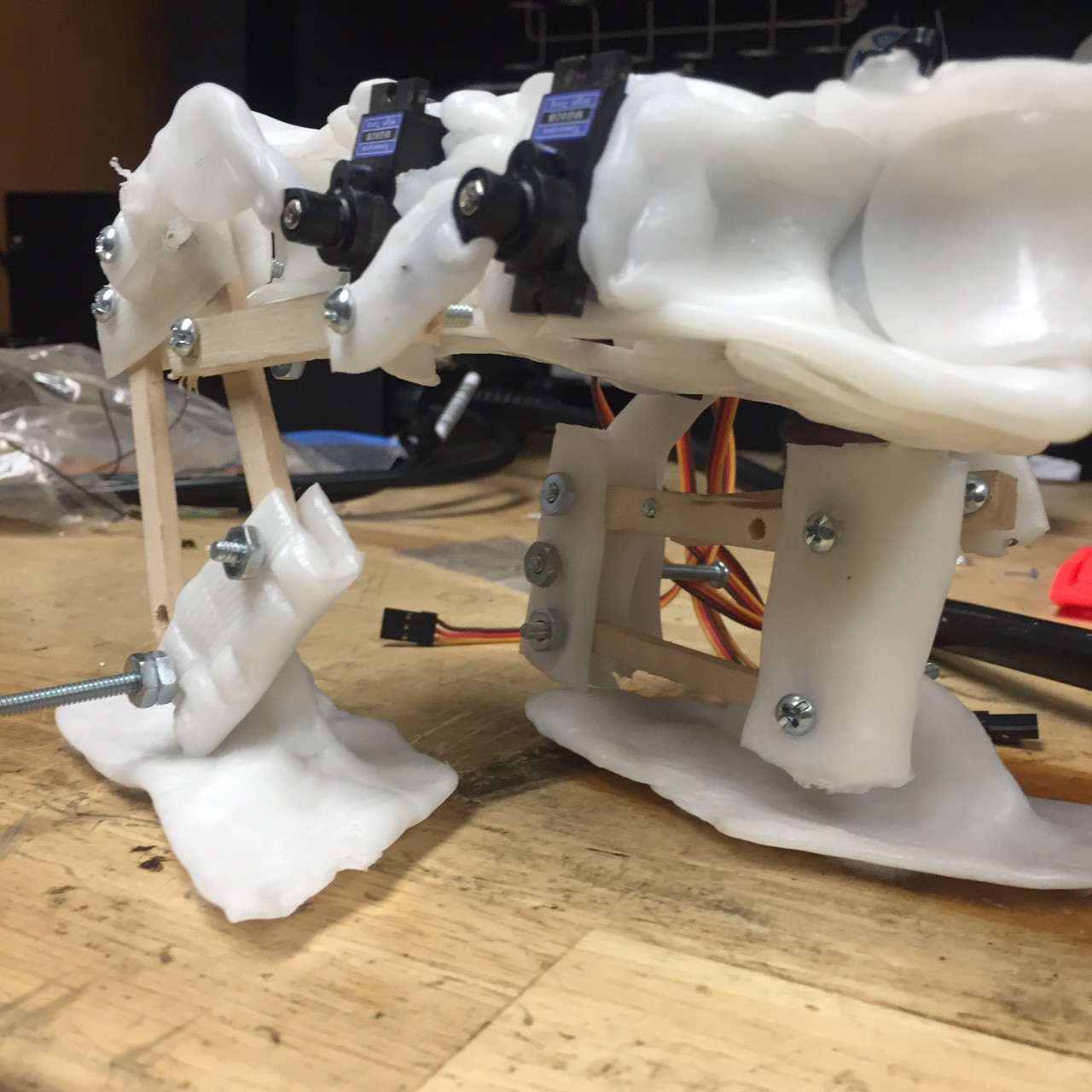
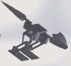
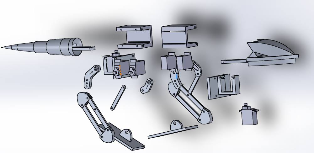
Image 2 – 3rd Generation of BiRex

The image above shows the finalized design before moving into producing our last model. Although the plastic molding made the structure too heavy to stay standing, the legs’ rotations resembled human-like walking motion.

Conclusion:
After changing the Mission Profile & Project Objective, we were able to focus our time into learning from trials and errors. This, along with a progressive design innovation, gave us enough data to create proper verification and validation tests.


Fall 2015 MicroBiped Interface Matrix Update

FINALIZED INTERFACE MATRIX & DEFINTIONS

By Railly Mateo (Systems Engineer)
Approved by Paul Oo (Project Manager)
Approved by Railly Mateo (Systems Engineer)

SzTI3jcuUVDzZkg

Table 1

Table 1 above show the 1st portion of project’s updated system interface definitions. The left side of the table has information on our subsystem components, while the right side is simply the microcontroller (Arduino Micro). Each component is then defined by its pinout data (pin number and pin symbol), which is then used as information for the microcontroller’s pinout.

7vtOa7MLNMDapYW

Table 2

Table 2 above show the 2nd portion of project’s updated system interface definitions. Unlike the first table, this section focuses only on our servo interface. The left side of the table has information on the servo driver, while the right side is simply 6 µservos. Because the servo driver has no numbered pins, the table separates each section of the servo driver by its basic connections (PWM, V+, & GND). The µservos are then connected to these connections through their PWM, V+, & GND wires.

A full system block diagram explains how these subsystems structurally connect.
The wiring diagram post explains how we planned to eliminate any possibility of branch-like wiring.


Fall 2015 MicroBiPed System Block Diagram Update

FINALIZED SYSTEM BLOCK DIAGRAM

By Railly Mateo (Systems Engineer)
Approved by Paul Oo (Project Manager)
Approved by Railly Mateo (Systems Engineer)

block diagram(1)

The block diagram above shows the updated block diagram for BiRex. The blocks are positioned based on their subsystem information. This post will give brief descriptions to explain each section of the block diagram.

The top left section comprises of two analog (orientation & distance) sensors. The ultrasonic sensor (HC-SR04) connects to the microcontroller (Arduino Micro) through the PWM & GPIO pins. The gyroscope (ITG-3200) connects the Arduino through its data line (SDA) and clock line (SCL).

The bottom left section comprises of 2 hardware devices (Bluetooth device & Android smartphone) for wireless communication between the Arxterra app and the microcontroller. The bluetooth device (HC-06) connects to the microcontroller through UART pins (RX & TX).

The top right section comprises of components (battery and voltage regulator) for energizing the system. The LiPo battery connects to the voltage regulator to ensure that we do not overload our subsystems. The voltage regulator (LM317) then uses our connections that bridge to the Vin and GND pins on the microcontroller.

Finally the bottom right section mechanical components (servos & servo driver). The servo driver (I2C interface) has two inputs and six outputs. It is energized from the battery and gets commands from the microcontroller through its data and clock lines. Then the signal is outputted to the six µservos (MG92B) allowing BiRex to walk.

Fall 2015 MicroBiPed Battery Update

BATTERY TRADE-OFF UPDATE

By Brian Walton (Manufacturing Engineer)
Approved by Paul Oo (Project Manager)
Approved by Railly Mateo (Systems Engineer)

Item Voltage Amphours Rating Quantity Price Per Qty
Dynamite LiPo Battery DYN 1419 7.4 V 2000 mAh 5C 1 $29.95
Lithium Ion Polymer Battery 3.7 V 2500 mAh 1C 2 $14.95
9V Battery 9V 120-1200mAh 1 $2+

The table above compares 3 possible batteries to use for the µBiPed project. The table compares supplied voltage, Amphours, rating, quantity, and price per quantity. The 3 batteries shown here on the table were chosen based off the updated mass and power reports.

Conclusion:
In the end we went with the Dynamite LiPo battery for multiple reasons:

  1. The price per quantity was negligible between the 7.4 and the 2 3.7 V batteries.
  2. While the 9V battery was cheaper short term, having rechargeable batteries are cheaper long term.
    1. Additionally this project being the feasibility demonstration of a toy, it’ll be better to have the toy already designed for rechargeable batteries.
  3. Even though the Lithium Ion had better rating for Amphours, the Dynamite Pro can handle better surges.

Fall 2015 MicroBiPed Mass Budget

FINALIZED MASS BUDGET

By Michael Balagtas (Manufacturing Engineer)
Approved by Paul Oo (Project Manager)
Approved by Railly Mateo (Systems Engineer)

12209101_1197484403601742_213187105_o

Part Quantity Individual Mass (grams) Total
(grams)
Margins
Servos 6 13.8 82.8 20%
#4 Hex Nuts and Bolts 18 20.7 372.6 10%
Frame 1 857.29 857.29 100%
Ultrasonic Sensor 1 8.5 8.5 10%
PCB (HC-06 & Arduino) 1 30.76 30.76 100%
Dynamite LiPo 1 86 86 10%
Grand Total (Grams) 1437.95 68%

The table above shows the data for mass of this year’s µBiPed project. The mass values obtained from data sheets are given a 10% margin of error. The frame’s mass is assumed to be an Aluminum build. Therefor, the mass may change drastically if a different material (polylactic acid) is more viable. The PCB mass is unknown, and was given an arbitrary value based on the components on the actual board. To account for different mounting methods, servos are given a 20% margin of error. This may change if custom flanges are utilized.

Fall 2015 MicroBiPed Battery

BATTERY TRADE-OFF

By Michael Balagtas (Manufacturing Engineer)
Approved by Paul Oo (Project Manager)
Approved by Railly Mateo (Systems Engineer)

Picking a battery with our level one requirements (Toy, compact, cheap) brings many conflicts to our final decision, so a trade-off study will be done between a generic 9V battery, two 3.7 LiPo batteries, and a Powerex Imedion AA batteries.

Our overall mission is very simple: climb up a short incline and come back down in a figure eight. At worst, the mission will take no longer than 10 minutes, and that is assuming that the robot will shuffle due to lack of traction. However, we still need to compensate for our large current requirements. The eight servos to be used have a current draw of about 150mAh each and the Arduino Micro has about 100mAh, putting our overall current budget to about 1.4Ah. Considering the mission duration, we can take some liberties with this amount and set our goal to about 300-400mAh. The characteristic curves of the batteries will be ignored to simplify this process.

Manufacturer Material Voltage Quantity Current Rating Dimensions Volume Price
Energizer Alkaline 9V 2 230mAh 46.4mm x 24.5mm x 15.5mm 17620mm3 $12.00
Syma Li-Po 3.7V 3 500mAh 42mm x 25mm x
9mm
9450mm3 $8.95
Imedion Ni-MH 1.2V 4 2400mAh N/A N/A $10.95

The table above compares 3 possible batteries to use for the µBiPed project. The table compares material, supplied voltage, quantity, current rating, dimension, volume, and price. After comparing the 3 batteries, we realized that the project needed to pushed further into manufacturing before we could decide which battery to choose.

Considering that the device is marketed as a toy, safety and choking hazards are a priority, therefore Lithium Ion is out of the picture, leaving us with the above options. At first glance, it looks as if the Imedion would be a landslide decision because of its current rating, but that’s too much for our mission parameters. To narrow down our decision, we will conduct a few studies: size, operational time, and price.

As a toy, cheap power sources is a requirement for easy access to power off the shelf. By and large, the Syma Li-Po wins over every other choice

We want the biped to be as small and as light as possible, so the smallest and lightest battery is the most desirable. However, the number of batteries is also taken into account. The Energizer only requires one battery to operate properly, whereas the Li-Po requires two and the Imedion requires four. The Syma Li-po would be comparable to that of a 9V battery once stacked together but they’re also light; the Imedion is tempting but there was no data for the batteries. As for right now, this study is a stalemate.

The last and most controversial of the above parameters is the current rating, because the current rating can change based on the current draw. Therefore, to streamline the process, it is assumed that these are ideal. The Imedion easily overpowers everyone else in this department because of its 2400mAh rating, but that is due to its unloaded nature. Nevertheless, we will assume that it takes the edge here

Conclusion: Either the Syam Li-Po or the Imedion will be utilized. The decision is heavily leaning towards the Syam because of the mass and given data.

Fall 2015 MicroBiped Distance Sensor

DISTANCE SENSOR TRADE-OFF

By Brian Walton (Controls Engineer)
Approved by Paul Oo (Project Manager)
Approved by Railly Mateo (Systems Engineer)

lidarImage provided by Sparkfun.com

SENSOR Sain SmartHC-SR04 LIDAR-Litev2
POWER SUPPLY 5 V 6 V
WORKING CURRENT 15 mA 2 mA
DIMENSION (45 x 20 x 15) mm (20 x 48 x 40) mm
RESOLUTION 0.3 cm 1 cm
PRICE $10.00 $115.00

The table above compares 2 possible sensors to use for the µBiPed project. The chart compares working voltage, working current, dimension, resolution, and price. After comparing the two sensors, the group decided on using the Ultrasonic Sensor for the purpose of having a more cost efficient payload.

  1. Sain SmartHC has better resolution
  2. Although the working current for the HC-SR04 is higher, the cost of purchasing a single LIDAR overweighs its positive trade-offs.

Fall 2015 MicroBiped Redefining The Mission

MISSION PROFILE & PROJECT OBJECTIVE UPDATE

By Paul Oo (Project Manager)
Approved by Paul Oo (Project Manager)
Approved by Railly Mateo (Systems Engineer)

After presenting the Project Design Requirements, the team met up with the President and Vice President to analyze the current status of the project. Realizing that creating a fully-functioning toy (that has to be spec’d for strict governmental standards such as remote control safety requirements) is not feasible for our allotted time to complete the project, the President suggested we change our mission profile and project objective to a feasibility demonstration.

Current Mission Profile & Project Objective:

Fall 2015 MicroBiPed (μBiPed) is inspired by the BiPed designed by Jonathan Dowdall of Project BiPed. The profile for this semester’s project is to use the BiPed & μBiPed designs to create a toy robot. The chosen design for a BiPed toy is a Tyrannosaurus Rex. To push the profile towards a feasibility demonstration requires a large emphasis on performance and budget. The objective of this project is to complete an obstacle course whilst controlled and communicating with the Arxterra™ Android application.    

Previous Mission Objective:

Fall 2015 MicroBiPed (μBiPed) is inspired by the BiPed designed by Jonathan Dowdall of Project BiPed. The objective for this year’s project is to use the BiPed & μBiPed designs to prototype a toy robot that resembles a Velociraptor. To push the objective towards prototyping a toy requires a large emphasis on cost. Although the mission is yet to be determined, the μBiPed must be controlled and be able to communicate with the Arxterra™ Android application.    


Fall 2015 MicroBiPed Microcontroller

MICROCONTROLLER TRADE-OFF

By Railly Mateo (Systems Engineer)
Approved by Paul Oo (Project Manager)
Approved by Railly Mateo (Systems Engineer)

microcontroller 

Microcontroller

PWM

Digital

I/O pins

Analog

Input

pins

Input

Voltage

Dimension

Flash & SRAM

Price

Arduino Micro

ATmega32u4

6

6

7 – 12V

68.6 x 53.4 mm

32 kB & 2 kB

$9.00

Arduino Uno

ATmega328

7

12

7-12V

48 x 18 mm

32 kB & 2.5 kB

$25.00

The above table compares 2 possible microcontrollers to use for the µBiPed project. The chart compares pins, input voltage, dimension, memory, and average price.

  1. The amount of pins available for analog and digital I/O’s are important because of the amount of sensors and servos the microcontroller will be connected to.
    1. We will need to connect 8 servos to analog pins on the microcontroller.
    2. We will need to connect 2 PWM pins to the payload.
  2. Input Voltage is used for understanding the amount of  voltage the batteries must supply.
  3. The dimensions are key to creating a transparent embedded system.
  4. Pricing is desired to lower the cost of the total budget.

After comparing the microcontrollers, the group decided on using the Arduino Micro for the purpose of having a smaller and most cost efficient microcontroller.

  1. Although the Arduino Uno has more pins, our BiPed will need no more than 8 PWM pins for our 8 servos.
  2. The microprocessors are also differentiated as either through-hole or surface mount. Considering that the 32u4 is a surface mount microprocessor, it has the advantage in compact design.
  3. Lastly, while the Uno has low margins for cost differentiation, the Micro ranges from $8.00 to $22.00. The difference in price is the main determinant for why the Arduino Micro was chosen.

Fall 2015 MicroBiped WBS – Team

WORK BREAKDOWN STRUCTURE 
(Team Members Schedule)

By Paul Oo (Project Manager)
Approved by Paul Oo (Project Manager)
Approved by Railly Mateo (Systems Engineer)

Table 1 – Project Manager

Operation Duration Start Finish Resource Name
Project μBiPed 162 days 8/31/15 12/10/15 Paul Oo
Project Management 155 days 9/10/15 12/10/15 Paul Oo
Mission Objective 21 days 9/10/15 10/1/15 Paul Oo
Program Req. 21 days 9/10/15 10/1/15 Paul Oo
Work Allocation 21 days 9/10/15 10/1/15 Paul Oo
PDD 8 days 9/23/15 10/1/15 Paul Oo
PDR 7 days 10/1/15 10/8/15 Paul Oo
CDD 21 days 10/8/15 10/29/15 Paul Oo
CDR 7 days 10/29/15 11/5/15 Paul Oo
Documentation 168 days 8/24/15 12/9/15 Paul Oo
Final Presentation 35 days 11/5/15 12/10/15 Paul Oo
Project Video 70 days 10/1/15 12/10/15 Paul Oo

The table above (Table 1) shows the schedule created for the Project Manager. This schedule has been made to fit Fall 2015’s 400 D timeline and milestones. Furthermore, the schedule has been broken down according to program tasks (Mission Objective, Work Allocation, & Documentation). To improve this schedule, along with other members’, project managers should view this document from the first day of being assigned to their position.

Table 2 – Systems Engineer

Operation Duration Start Finish Resource Name
Systems Engineering 155 days 9/10/15 12/10/15 Railly Mateo
Project & Level 2 Req 13 days 9/10/15 9/23/15 Railly Mateo
System Block Diag. 8 days 9/23/15 10/1/15 Railly Mateo
Instructions Pamphlet 8 days 10/8/15 10/15/15 Railly Mateo
Hardware 14 days 9/23/15 10/7/15 Railly Mateo
Fritzing – System 8 days 9/23/15 10/7/15 Railly Mateo
Interface Design 2 days 10/6/15 10/7/15 Railly Mateo
Software 34 days 9/17/15 10/21/15 Railly Mateo
Arduino IDE 14 days 9/17/15 10/1/15 Railly Mateo
Bluetooth 4 days 10/8/15 10/11/15 Railly Mateo
Arxterra App 10 days 10/11/15 10/21/15 Railly Mateo
Testing 70 days 10/1/15 12/9/15 Railly Mateo
Subsystem/Syst. TP 70 days 10/1/15 12/9/15 Railly Mateo

The table above (Table 2) shows the schedule created for the Systems Engineer. The schedule has been broken down according to project tasks (Project & Level 2 Requirements, Hardware, Software, & Testing). To improve this schedule, along with other members’, system engineers should view this document from the first day of being assigned to their position. Systems engineers must be able to provide startup/error support to any subsystem.

Table 3 – Manufacturing Engineer

Operation Duration Start Finish Resource Name
Manufacturing 155 days 9/10/15 12/10/15 Michael Balagtas
Subsystem & L 2 Req. 13 days 9/10/15 9/23/15 Michael Balagtas
Design 14 days 9/23/15 10/7/15 Michael Balagtas
AutoCAD 3D Model 21 days 9/23/15 10/15/15 Michael Balagtas
EagleCAD High Level 2 days 10/6/15 10/7/15 Michael Balagtas
Production 44 days 10/1/15 11/15/15 Michael Balagtas
Fast-Prototype 15 days 10/1/15 10/15/15 Michael Balagtas
CNC Structure 8 days 10/15/15 10/22/15 Michael Balagtas
PCB Circuit board 38 days 10/8/15 11/15/15 Michael Balagtas
Testing 70 days 10/1/15 12/9/15 Michael Balagtas
Structure 70 days 10/1/15 12/9/15 Michael Balagtas
Electronics 70 days 10/1/15 12/9/15 Michael Balagtas

The table above (Table 3) shows the schedule created for the Manufacturing Engineer. The schedule has been broken down according to project tasks (Subsystem & Level 2 Requirements, Design, Production, & Testing). To improve this schedule, along with other members’, manufacturing engineers should view this document from the first day of being assigned to their position. Systems engineers must be able to provide startup/error support to any subsystem. In return, the subsystem engineers must be able to effectively produce level 2 requirements that meets project requirements.

Table 4 – Controls Engineer

Operation Duration Start Finish Resource Name
Controls & Process 155 days 9/10/15 12/10/15 Brian Walton
Subsystem & L 2 Req. 13 days 9/10/15 9/23/15 Brian Walton
Performance 21 days 9/23/15 10/15/15 Brian Walton
Arduino IDE Code 21 days 9/23/15 10/15/15 Brian Walton
EagleCAD Low Level 2 days 10/6/15 10/7/15 Brian Walton
Troubleshoot 37 days 10/7/15 11/15/15 Brian Walton
LTSPICE Simulations 37 days 10/7/15 11/15/15 Brian Walton
PID Control 37 days 10/7/15 11/15/15 Brian Walton
Testing 70 days 10/1/15 12/9/15 Brian Walton
Structure 70 days 10/1/15 12/9/15 Brian Walton
Electronics 70 days 10/1/15 12/9/15 Brian Walton

The table above (Table 4) shows the schedule created for the Controls Engineer. The schedule has been broken down according to project tasks (Subsystem & Level 2 Requirements, Performance, Troubleshoot, & Testing). To improve this schedule, along with other members’, controls engineers should view this document from the first day of being assigned to their position. Systems engineers must be able to provide startup/error support to any subsystem. In return, the subsystem engineers must be able to effectively produce level 2 requirements that meets project requirements.