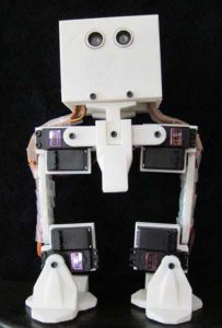
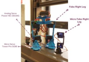
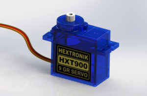
Spring 2018: Project BiPed: Verification and Validation Pass/Fail Matrix

By: Jeffrey De La Cruz (Mission, Systems, and Test Engineer)

Verified By: Miguel Gonzalez (Project Manager)

Approved By: Miguel Garcia (Quality Assurance)


Table of Contents

Introduction

The Level 1 and Level 2 requirements verification pass/fail matrix will demonstrate if the BiPed functions properly. Each requirement state will be tested by a specific verification method. The verification methods consist of Test, Analysis, Demonstration, and Inspection. As project BiPed continues, the results tools, procedure, and results section will be filled depending on the level requirement. This will determine whether the level requirements pass or fail the verification. The Level 1 and Level 2 requirements are separated in order.

Purpose

The purpose of this document is to provide a comprehensive Verification and Validation (V&V) Test Plan of the Spring 2018 Micro FOBO, including the Project ConOps/Mission, Test Methodology, Verification and Validation Matrices, and Test Cases.


Project ConOps/Mission

The mission is to create a toy robot that can be controlled and navigate the toy robot through a 2D maze. The toy robot would then be capable to travel through the maze repeating the same route from its first walkthrough of the maze.

Document Overview

This document is organized as follows:

  • Section 2 contains links to relevant and applicable project reference documents and presentations for this Test Plan.
  • Section 3 contains a description of the Testing Methodology utilized in this Test Plan, including the Master Verification and Validation Matrix, a description of the 4 types of V&V testing performed, the Test Environment(s) description(s), and a Master Test Case List of all (number #) Test Cases for this project.

Applicable Documents

This section contains a table of all relevant and applicable project reference documents and presentations for the Micro FOBO Spring 2018 Verification and Validation Test Plan.

Document Name Document Description Document Link
Research for Micro FOBO Contains research for Micro FOBO. Links to documents helpful to work on Micro FOBO. Research
Project BiPed Website Contains information regarding Jonathon Dowdall’s FOBO FOBO
PDD Preliminary Design Document. Contains xxxxxx PDD
PDR Preliminary Design Review Presentation. Contains L1 and L2 Requirements, System Block Diagram, Resource Allocation Reports, trade studies,xxxxxx PDR
Final Project Summary Final Presentation of completed Project. Contains xxxxxx Currently not available
NASA Systems Engineering Handbook (2007) Document containing Test Methodologies in Section 3 http://www.acq.osd.mil/se/docs/NASA-SP-2007-6105-Rev-1-Final-31Dec2007.pdf

Testing Methodology

This section contains the Master Verification and Validation Matrix, as well as detailed descriptions of the various Test Methods and Test Cases utilized in this Test Plan.

Master Verification and Validation (V&V) Matrix

This matrix provides complete traceability of every requirement. Specifically, every requirement is mapped to its description, success criteria, V&V testing designation and method, and Test Case(s) where the requirement will be tested. Note that some overlap between Test Cases’ requirements V&V is okay.

Level One Requirements

Requirement Number Requirement Text Verification Success Criteria Verification Method (Test, Analysis, Demonstration, Inspection) Test Case #
L1-1 Micro FOBO will stand on its own without any physical help. Micro stands on its own without any assistance. Inspection 2
L1-2 Micro FOBO’s electronic components will be easily assembled and disassembled from the robot’s head. Micro FOBO’s electronic components are easily assembled and disassembled from the robot’s head Inspection 2
L1-3 Micro FOBO will have 2 legs Micro FOBO has two legs. Inspection 2
L1-4 Micro FOBO will be a toy robot based on the design of the FOBO from Jonathan Dowdall. Micro FOBO is a toy robot based on Jonathan Dowdall Inspection 1
L1-5 Micro FOBO will fit within the classroom cabinets. 28”x13”x14.5” Micro FOBO fits in the cabinet within those dimensions Inspection 5
L1-6 Micro FOBO will utilize a 3DoT board or Sparkfun Pro Micro 3.3V/8MHz. Micro FOBO utilizes a 3DoT board or Sparkfun Pro Micro 3.3V/8MHz Inspection 2
L1-7 Micro FOBO’s part components will be 3D printed using the material carbon fiber PLA Micro FOBO’s parts are 3D printed using carbon fiber PLA Inspection 1
L1-8 Micro FOBO will not exceed a print time of 7.80 hours. Upon approval of waiver Micro FOBO does not take longer than 7.80 hours to print. Inspection 1
L1-9 Micro FOBO shall not exceed a cost of $250.00 to construct. Cost does not exceed $250.00 Inspection 5
L1-10


Micro FOBO shall be 63% of the overall size of Jonathan Dowdall’s FOBO. Micro FOBO is smaller than original FOBO by 63% or less


Inspection/Analysis


2
L1-11 Micro FOBO shall detect intersections of the maze. Micro FOBO detects intersections of the maze. Demonstration 3
L1-12 Micro FOBO shall be able to perform static walking Micro FOBO performs static walking Inspection 3
L1-13 Micro FOBO shall produce a 90-degree turn. Micro FOBO turns Demonstration 3
Requirement Number Requirement Text Verification Success Criteria Verification Method (Test, Analysis, Demonstration, Inspection) Test Case #
L1-14 The user shall guide the Micro FOBO through the maze with the use of the Arxterra application. The user guides the Micro FOBO through the maze using the Arxterra application Demonstration 3
L1-15 Micro FOBO shall record the path of the maze Micro FOBO records the path of the maze Demonstration 3
L1-16 Micro FOBO shall traverse the maze using the recorded path. Micro FOBO traverses the maze using the recorded path Demonstration 3
L1-17 Micro FOBO shall traverse cloth, paper, and linoleum. Micro FOBO walks on cloth, paper, and linoleum. Demonstration 4
L1-18 Micro FOBO will utilize a printable circuit board. Micro FOBO utilizes a printable circuit board. Inspection 2
L1-19 The final biped shall be physically completed by May 10, 2018 Micro FOBO is physically completed by May 10, 2018 Inspection 1
L1-20 Micro FOBO should step over a square rod 1cm tall by 1cm wide by 10 cm long Micro FOBO steps over a square rod of 1cm tall by 1cm wide by 10cm long. Demonstration 4
L1-21 Micro FOBO should be able to perform dynamic walking. Micro FOBO performs dynamic walking Demonstration 3

Level Two Requirements

Requirement Number Requirement Text Verification Success Criteria Verification Method (Test, Analysis, Demonstration, Inspection) Test Case #
L2-1 Micro FOBO will be connected via Bluetooth to the app on an android phone Micro FOBO connects via Bluetooth Demonstration 3
L2-2 Micro FOBO dimensions of robot will need to be small enough to fit in a 4in by 4in box for maze purposes. Micro FOBO fits in the 4in by 4in square of the maze. Inspection 5
L2-3 Micro FOBO will use eight micro servos. Micro FOBO has eight micro servos Inspection 2
L2-4 Micro FOBO will use UV sensors to detect the colors of the maze. Micro FOBO UV sensor detects the colors of the maze Demonstration 2
L2-5 By detecting the colors of the maze, the Micro FOBO shall determine if it is at an intersection. (intersection detection) Using the colors of the maze, Micro FOBO detects an intersection Test 3
L2-6 Micro FOBO shall use a battery that outputs 3.7V Test 2
L2-7 The user shall use the Arxterra application to move the robot forward, left, and right. Micro FOBO moves forward, left and right. Test 3
L2-8 Micro FOBO’s wiring shall be able to connect and reconnect in 10 min or less The wiring for Micro FOBO’s connects in 10 min or less. Inspection 1
Requirement Number Requirement Text Verification Success Criteria Verification Method (Test, Analysis, Demonstration, Inspection) Test Case #
L2-9 Micro FOBO wiring shall be nice and clean with the usage of terminal blocks, contact pins, 2.0mm PH series JST connectors, and barrel connectors Micro FOBO’s wiring is nice and clean using terminal blocks, contact pins, 2.0mm PH series JST connectors, and barrel connectors. Demonstration/inspection 1
L2-10 Micro FOBO shall play a musical tune when the maze is completed Micro FOBO plays a musical tun when the maze is completed. Inspection 4
L2-11 Micro FOBO shall have indicating LEDs to demonstrate if micro FOBO is on. Micro FOBO has LEDs and the LEDs turn on. These LEDs  indicate whether its on. 2
L2-12 Micro FOBO shall record the path of the maze the Micro FOBO traverses on the 3DoT board or the Sparkfun Pro Micro 3.3V/8MHz to navigate the robot through the maze. Micro FOBO records the path of the maze and navigates micro FOBO through the maze. Demonstration 3
L2-13 Micro FOBO shall use a 3D printed carbon fiber PLA head chassis and leg components. Micro FOBO’s head chassis and leg components are 3D printed using the carbon fiber PLA. Inspection 1
L2-14 Micro FOBO shall measure 4.5” x 3.25” x 7.25” (l x w x h) Micro FOBO measures 4.5” x 3.25” x 7.25” (l x w x h) Inspection/Analysis 2
L2-15 Micro FOBO shall weigh 460g Micro FOBO weighs at or near 460 grams. 2
L2-16 Micro FOBO shall detect objects 8 inches from it. Micro FOBO detects an object 8 inches from it Demonstration 3
L2-17 Micro FOBO should be able detect other robots and avoid collision. Micro FOBO should stop completely and wait for command Micro FOBO detects other robots in the maze and stops. It stops and awaits command. Demonstration 3
L2-18 Micro FOBO should take a bow at the end of the maze. Micro FOBO takes a bow at the end of the maze. Demonstration 4

Testing Types and Methods

This subsection contains the 4 types of Verification and Validation (V&V) testing, as derived from the NASA Systems Engineering Handbook referenced above in Section 2. The material is taken from Chapter 5 in the NASA Handbook and replicated below.

Verification proves that a realized product for any system model within the system structure conforms to the build-to requirements (for software elements) or realize-to specifications and design descriptive documents (for hardware elements, manual procedures, or composite products of hardware, software, and manual procedures). In other words, Verification is requirements driven; verification shows proof of compliance with requirements; that the product can meet each “shall” statement as proven through a performance of a test, analysis, inspection, or demonstration.

Validation is conducted under realistic conditions (or simulated conditions) on an end product for the purpose of determining the effectiveness and suitability of the product for use in mission operations by typical users; and the evaluation of the results of such tests. Testing is the detailed quantifying method of both verification and validation. However, testing is required to validate final end products to be produced and deployed. In other words, Validation is ConOps/Mission-driven; validation shows that the product accomplishes the intended purpose in the intended environment; that product meets the expectations of the customer and other stakeholders as shown through the performance of a test, analysis, inspection, or demonstration.

Verification by Analysis

The use of mathematical modeling and analytical techniques to predict the suitability of a design to stakeholder expectations based on calculated data or data derived from lower system structure end product verifications. Analysis is generally used when a prototype; engineering model; or fabricated, assembled, and integrated product is not available. Analysis includes the use of modeling and simulation as analytical tools. A model is a mathematical representation of reality. A simulation is the manipulation of a model.

Verification by Demonstration

Showing that the use of an end product achieves the individual specified requirement. It is generally a basic confirmation of performance capability, differentiated from testing by the lack of detailed data gathering. Demonstrations can involve the use of physical models or mockups; for example, a requirement that all controls shall be reachable by the pilot could be verified by having a pilot perform flight-related tasks in a cockpit mockup or simulator. A demonstration could also be the actual operation of the end product by highly qualified personnel, such as test pilots, who perform a one-time event that demonstrates a capability to operate at extreme limits of system performance, an operation not normally expected from a representative operational pilot.

Verification by Inspection

The visual examination of a realized end product. Inspection is generally used to verify physical design features or specific manufacturer identification. For example, if there is a requirement that the safety arming pin has a red flag with the words “Remove Before Flight” stenciled on the flag in black letters, a visual inspection of the arming pin flag can be used to determine if this requirement was met.

Verification by Test

The use of an end product to obtain detailed data needed to verify performance, or provide sufficient information to verify performance through further analysis. Testing can be conducted on final end products, breadboards, brass boards or prototypes. Testing produces data at discrete points for each specified requirement under controlled conditions and is the most resource-intensive verification/validation technique. As the saying goes, “Test as you fly, and fly as you test.” (See Subsection 5.3.2.5.).

Validation by Analysis

The use of mathematical modeling and analytical techniques to predict the suitability of a design to stakeholder expectations based on calculated data or data derived from lower system structure end product validations. It is generally used when a prototype; engineering model; or fabricated, assembled, and integrated product is not available. Analysis includes the use of both modeling and simulation.

Validation by Demonstration

The use of a realized end product to show that a set of stakeholder expectations can be achieved. It is generally used for a basic confirmation of performance capability and is differentiated from testing by the lack of detailed data gathering. Validation is done under realistic conditions for any end product within the system structure for the purpose of determining the effectiveness and suitability of the product for use in NASA missions or mission support by typical users and evaluating the results of such tests.

Validation by Inspection

The visual examination of a realized end product. It is generally used to validate physical design features or specific manufacturer identification.

Validation by Test

The use of a realized end product to obtain detailed data to validate performance or to provide sufficient information to validate performance through further analysis. Testing is the detailed quantifying method of both verification and validation but it is required in order to validate final end products to be produced and deployed.

Master Test Case List

A Test Case can be described as a scenario containing a sequence of detailed test steps, in order to perform verification/validation testing on multiple requirements that are similar in nature.

For example, if a group has multiple requirements regarding starting up their robot project, they can group all these requirements to be verified/validated in a single test case. Similarly, if a group has multiple requirements that can be verified/validated via inspection, they can group all of them together in a single test case.

The purpose of this subsection is to provide a High-Level overview of all Test Cases utilized in this Test Plan. Each item in this subsection will contain the following: Test Case Number and Name, High-Level Scenario Description, and Test Environment Description.

TC-01: Creation, Construction, and Completion of Micro FOBO

Description: Micro FOBO is a toy biped robot based on the design of Jonathon Dowdall’s FOBO. Micro FOBO will be 3D printed using the carbon fiber PLA and will not exceed a print time of 7.80 hours. The head chassis and leg components will be 3D printed using this material. Micro FOBO’s wiring connection does not take more than 10 min and it will contain the usage of terminal blocks, contact pins, 2.0mm PH series JST connectors and barrel connectors. The final physical rendition of micro FOBO shall be completed by May 10, 2018. This test case describes the creation, construction, and completion of micro FOBO. The design, the material used on the components, the print time and the date is described in this test case. These requirements are grouped together because of the conditions of the creation and completion of micro FOBO.

Test Environment: The test case takes place in a classroom.

TC-02: Physical Attributes of Micro FOBO

Description:  This test case consists of anything physical attributes of the micro FOBO. While the previous test case discusses the creation and completion of micro FOBO, this test case will include the requirements that micro FOBO has physically. Micro FOBO electronics components will be easily assembled and disassembled. It will contain two legs that will help it stands on its own without any physical help from the group. A total of 8 servos will be in the legs. Micro FOBO overall size is about 60% of the overall size of Jonathon Dowdall’s FOBO. The dimensions of micro FOBO are: 4.5”x3.25”x7.25”(l x w x h). On the left and right side of micro FOBO’s head, it will contain one LED on each side to indicate whether its turning left or right. Micro FOBO will include a UV sensor to detect colors, will include a custom PCB for sensors and servos, a battery that outputs 3.7 V, a 3DOT board or Pro Micro 3.3V/8MHz. Micro FOBO weight will not exceed 460g. These are grouped together because these are qualities of micro FOBO that are physical.

Test Environment: These test cases take place inside of a classroom.

TC-03: Functionality of Micro FOBO

Description: Functionality of micro FOBO test case consists anything micro FOBO will do to function properly and also the connection and utility of the Arxterra application. This consists of micro FOBO’s ability to detect intersections using the colors of the maze and determine whether to turn and make a 90-degree turn. Micro FOBO functionality to perform a static walk and/or dynamic walk. This test case also contains the user guide of micro FOBO through the maze by connecting the micro FOBO via Bluetooth to the Arxterra application, the recording of the path of the maze, and micro FOBO’s traversing the maze using the recorded path. The user can make the micro FOBO turn forward, turn left, and turn right. Lastly, the micro FOBO detects objects 8 inches from it and should be able to detect other robots and avoid collisions.

Test Environment: This test case will take place inside a classroom

TC-04: Micro FOBO’s Extra Functionality and Challenges

Description: This test case discusses extra functionality the micro FOBO performs whether it being on the maze or on the table and challenges and/or obstacles. For example, a challenge that micro FOBO can perform is walking on different terrain field like linoleum, cloth, and paper. Another challenge for micro FOBO will be to walk over a square rod that measure 1cm tall, 1 cm wide and 10 cm long. Micro FOBO playing a musical tune and taking a bow when it finishes the maze. These requirements were grouped together because these requirements are extra functionality and challenges for micro FOBO.

Test Environment: This test case will take place inside a classroom.

TC-05: Cost, Storage, Fitting in Maze Dimensions

Description: This test case consists of micro FOBO’s cost, being able to fit in ECS 316 cabinets for storage, and being able to fit the 4 in by 4 in maze squares. These requirements were grouped together because these requirements did not relate to any of the previous test cases.

Test Environment: This test case will take place inside a classroom.

Test Procedures

This section contains details of every Test Case utilized for V&V of project requirements. Each Test Case subsection within this section will contain the following: Test Case number and name, detailed scenario description, Test Case Traceability Matrix, detailed success criteria, detailed Test Environment description, Test Assumptions/Preconditions, Detailed Test Procedure Steps, and a Pass/Fail Matrix of success criteria per Test Case.

TC-01: Creation Construction, and Completion of Micro FOBO

Detailed Description


This is test case describes the creation, construction, and completion of micro FOBO. For each aspect of creation construction, and completion provides certain conditions of how micro FOBO is physically done. It is going from the step of being 3D printed to assembling it together to being completed. The goal of this test case to demonstrate this and the requirements grouped for this test case are essential for the micro FOBO to be created, constructed and completed.

Test Case Traceability and Pass/Fail Matrix

This matrix shall show all requirements that are being tested in this test case. The Pass/Fail Column is populated after the Test Case has been run via the Procedure Steps.

Requirement Number Requirement Text Verification Success Criteria Verification Method (Test, Analysis, Demonstration, Inspection) Pass/Fail
L1-4 Micro FOBO will be a toy robot based on the design of the FOBO from Jonathan Dowdall. Micro FOBO is a toy robot based on Jonathan Dowdall Inspection Pass
L1-7 Micro FOBO’s part components will be 3D printed using the material carbon fiber PLA Micro FOBO’s parts are 3D printed using carbon fiber PLA Inspection Pass
L1-8 Micro FOBO will not exceed a print time of 7.80 hours. Upon approval of waiver Micro FOBO does not take longer than 7.80 hours to print. Inspection Pass
L1-19 The final biped shall be physically completed by May 10, 2018 Micro FOBO is physically completed by May 10, 2018 Inspection Pass
L2-8 Micro FOBO’s wiring shall be able to connect and reconnect in 10 min or less The wiring for Micro FOBO’s connects in 10 min or less. Inspection Pass
L2-9 Micro FOBO wiring shall be nice and clean with the usage of terminal blocks, contact pins, 2.0mm PH series JST connectors, and barrel connectors Micro FOBO’s wiring contains these type of wires and it is nice and clean. Inspection Pass
L2-13 Micro FOBO shall use a 3D printed carbon fiber PLA head chassis and leg components. Micro FOBO’s head chassis and leg components are 3D printed using the carbon fiber PLA. Inspection Pass

Detailed Success Criteria

In order for this test case to be successful, each of the requirements needs to pass. The goal of this test case will demonstrate that micro FOBO is physically complete beginning from being 3D printed to being built piece by piece. Therefore, the title of this test case goes to explain micro FOBO’s creation, construction, and completion.

Test Environment

This test case will be taking place in the ECS building in room 316. This is where each step of the test case will be presented and show the physically complete micro FOBO.

Assumptions and Preconditions

  • 3D printer will function properly and print parts successfully

Procedure Steps

Step Number Step Description Pass Criteria Recorded Data Requirement(s) Tested Test Method
1 Inspect Jonathon Dowdall’s FOBO and compare it with micro FOBO Micro FOBO Is a toy robot based on Jonathon Dowdall’s FOBO L1-4 Inspection
2 Examine micro FOBO and determine and compare with different material used in 3D printed. Micro FOBO’s parts are 3D printed using the carbon fiber PLA. L1-7 Inspection
3 Examine the print time of the mini FOBO. The print time document is here. The total print time should not exceed a time of 7.80 hours L1-8 Inspection
4 Place a physically completed micro FOBO on the table The completed micro FOBO  is physically ready by May 10 2018. L1-19 Inspection
5 With none of the wires connected, the assembly of micro FOBO will be demonstrated. Once the it is assembled, micro FOBO will then be disassembled. The assembly and disassembly for micro FOBO will not exceed the time of 10 mins. L2-8 Demonstration
6 During assembly, the wires will be inspected and determined whether the correct The wiring of micro FOBO is nice and clean and uses 2.0mm PH series JST connectors and barrel connectors. L2-9 Inspection
7 Inspecting the micro FOBO’s head chassis and leg components, it will be determined if the material carbon fiber PLA is used. Micro FOBO’s head chassis and leg components are 3D printed using carbon fiber PLA L2-13 Inspection

TC-02: Physical Attributes of Micro FOBO

Detailed Description

The Physical Attributes of Micro FOBO test case discusses every components and equipment that the micro FOBO has or utilizes. For example, micro FOBO requires 8 servos in order to stand and to walk. Anything that describes that the micro FOBO needs physically in order to walk through the maze will be in this test case. The goal of this test case is to demonstrate the physical attributes that micro FOBO will need and utilize.

Test Case Traceability and Pass/Fail Matrix

This matrix shall show all requirements that are being tested in this test case. The Pass/Fail Column is populated after the Test Case has been run via the Procedure Steps.

Requirement Number Requirement Text Verification Success Criteria Verification Method (Test, Analysis, Demonstration, Inspection) Pass/Fail
L1-1 Micro FOBO will stand on its own without any physical help. Micro stands on its own without any assistance. Inspection Pass
L1-2 Micro FOBO’s electronic components will be easily assembled and disassembled. Micro FOBO’s electronic components are easily assembled and disassembled Inspection Pass
L1-3 Micro FOBO will have 2 legs Micro FOBO has two legs. Inspection Pass
L1-6 Micro FOBO will utilize a 3DoT board or Sparkfun Pro Micro 3.3V/8MHz. Micro FOBO utilizes a 3DoT board or Sparkfun Pro Micro 3.3V/8MHz Inspection Pass
L1-10 Micro FOBO shall be 63% of the overall size of Jonathan Dowdall’s FOBO. Micro FOBO is smaller than original FOBO by 63% or less


Inspection Pass
L1-18 Micro FOBO will utilize a printable circuit board. Micro FOBO utilizes a printable circuit board. Inspection Pass
L2-3 Micro FOBO will use eight micro servos. Micro FOBO has eight micro servos Inspection Pass
L2-4 Micro FOBO will use UV sensors to detect the colors of the maze. Micro FOBO UV sensor detects the colors of the maze Inspection Pass
L2-6 Micro FOBO shall use a battery that outputs 3.7V A battery that outputs 3.7V is used. Inspection Pass
L2-11


Micro FOBO shall have indicating LEDs to demonstrate if micro FOBO is on. Micro FOBO has LEDs and the LEDs turn on. These LEDs  indicate whether its making a left or right turn. Inspection


Pass
L2-14 Micro FOBO shall measure 4.5” x 3.25” x 7.25” (l x w x h) Micro FOBO measures 4.5” x 3.25” x 7.25” (l x w x h) Demonstration Pass
L2-15 Micro FOBO shall weigh 460g Micro FOBO weighs at or near 460 grams. Inspection Pass

Detailed Success Criteria

In order for this test case to be successful, the physical components of the micro FOBO need to present. Each of the requirements of this test case are needed for the micro FOBO to even begin to navigate the maze. Without some of these requirements, micro FOBO would not be able to perform properly. For example, micro FOBO requires two legs and these two legs will help the micro FOBO to be able to stand without any assistance.

Test Environment

This test case will be taking place in the ECS building in room 316.

Assumptions and Preconditions

  • The 3D printed parts were printed properly
  • Micro FOBO was constructed properly

Procedure Steps

Step Number Step Description Pass Criteria Recorded Data Requirement(s) Tested Test Method
1 Micro FOBO will be placed on a flat surface. Once placed on a flat surface, micro FOBO stands without L1-1 Inspection
2 Micro FOBO assembly is demonstrated. The ease of the assembly and disassembly will be Micro FOBO is easily assembled and disassembled. L1-2 Inspection
3 A completed Micro FOBO will placed on a flat surface. By inspection, micro FOBO has two legs. L1-3 Inspection
4 Having a 3DOT board and/or Sparkfun Pro Micro 3.3v/8Mhz A 3DOT board and/or Sparkfun Pro Micro 3.3V/8MHz is present L1-6 Inspection
5 Place FOBO and micro FOBO side by side and take measurements Micro FOBO is smaller by 63% less  than original FOBO L1-10 Inspection/Analysis
6 A printable circuit is placed on the table counter. A printable circuit board is present L1-18 Inspection
7 A completely built micro FOBO is on the table. The micro servos on the FOBO are to be counted. Eight micro servos are present in the micro FOBO L2-3 Inspection
8 A UV sensor is placed on the counter table. Upon inspecting, there is UV sensor present. L2-4 Inspection
9 Measure the battery with a voltmeter and determine the volts of the battery. A battery that outputs 3.7V is present and helps function micro FOBO L2-6 Inspection/Analysis
10 Inspecting a completed micro FOBO, two LEDs will be on the head chassis. These LEDs will show that the micro FOBO is on. Two LEDs are on the head chassis turn on indicating that the micro FOBO is on. L2-11


Inspection
11 A completed micro FOBO will be measured with a ruler. Measurements will be noted. Micro FOBO measurements are 4.5” x 3.25” x 7.25” (l x w x h) L2-14 Inspection/Analysis
12 A completed micro FOBO weight will be measured on a scale. And Micro FOBO does not exceed a total weight of 460 grams. L2-15 Inspection/Analysis

TC-03: Functionality of Micro FOBO

Detailed Description

The goal of this test case is to demonstrate the functionality of micro FOBO. this is test case describes the creation, construction, and completion of micro FOBO. For each aspect of creation construction, and completion provides certain conditions of how micro FOBO is physically done. It is going from the step of being 3D printed to assembling it together to being completed.

Test Case Traceability and Pass/Fail Matrix

This matrix shall show all requirements that are being tested in this test case. The Pass/Fail Column is populated after the Test Case has been run via the Procedure Steps.

Requirement Number Requirement Text Verification Success Criteria Verification Method (Test, Analysis, Demonstration, Inspection) Pass/Fail
L1-11 Micro FOBO shall detect intersections of the maze. Micro FOBO detects intersections of the maze. Inspection Fail
L1-12 Micro FOBO shall be able to perform static walking Micro FOBO performs static walking Inspection Fail
L1-13 Micro FOBO shall produce a 90-degree turn. Micro FOBO turns at 90-degree turn Inspection Fail
L1-14 The user shall guide the Micro FOBO through the maze with the use of the Arxterra application. The user guides the Micro FOBO through the maze using the Arxterra application Inspection Fail
L1-15 Micro FOBO shall record the path of the maze Micro FOBO records the path of the maze Inspection Fail
L1-16 Micro FOBO shall traverse the maze using the recorded path. Micro FOBO traverses the maze using the recorded path Inspection Fail
L1-21 Micro FOBO should be able to perform dynamic walking. Micro FOBO performs dynamic walking Inspection Fail
L2-1 Micro FOBO will be connected via Bluetooth to the app on an android phone Micro FOBO connects via Bluetooth using an android phone Inspection Fail
L2-5 By detecting the colors of the maze, the Micro FOBO shall determine if it is at an intersection. (intersection detection) Using the colors of the maze, Micro FOBO detects an intersection Inspection Fail
L2-7 The user shall use the Arxterra application to move the robot forward, left, and right. Micro FOBO moves forward, left and right. Inspection/Analysis


Fail
L2-12 Micro FOBO shall record the path of the maze the Micro FOBO traverses on the 3DoT board or the Sparkfun Pro Micro 3.3V/8MHz to navigate the robot through the maze. Micro FOBO records the path of the maze and navigates micro FOBO through the maze. Demonstration Fail
L2-16 Micro FOBO shall detect objects 8 inches from it. Micro FOBO detects an object 8 inches from it Inspection Fail
L2-17 Micro FOBO should be able detect other robots and avoid collision. Micro FOBO should stop completely and wait for command Micro FOBO detects other robots in the maze and stops. It stops and awaits command. Demonstration Fail

Detailed Success Criteria

The success of this test case will show the functionality of micro FOBO. These functions of micro FOBO will help it traverse the maze. These are different than the ones from test case 4 as in these functions are required to walk the maze. These test cases are what is required for the group project.

Test Environment

This test case will be taking place in ECS 316.

Assumptions and Preconditions

  • Previous two test cases are completed.
  • The code is running properly.
  • Parts are functioning properly.

Procedure Steps

Step Number Step Description Pass Criteria Recorded Data Requirement(s) Tested Test Method
1 While micro FOBO is walking in the maze, it will use its UV sensor to Micro FOBO detects an intersection in the maze. A value is recorded L1-11 Demonstration
2 A functional micro FOBO will be placed on the table counter. The code for micro FOBO will be Micro FOBO is able to static walk L1-12 Demonstration
3 While the micro FOBO is running, the micro FOBO will attempt to turn. A 90-degree turn is produced while it is attempting to turn. L1-13 Demonstration
4 While the user is connected to the micro FOBO, the user should be able to guide micro FOBO through the maze. The user is able to guide micro through the maze. L1-14 Demonstration
5 While traversing the maze, micro FOBO records the maze. Micro FOBO records the path of the maze it took. L1-15 Demonstration
6 Using the recorded path of the maze, micro FOBO will traverse this path Micro FOBO traverses the record path. L1-16 Demonstration
7 While micro FOBO is walking, a dynamic can be inspected. Micro FOBO dynamic walks. L1-21 Demonstration
8 Using the Arxterra application, micro FOBO will be connected via Bluetooth. Micro FOBO is connected via Bluetooth L2-1 Demonstration
9 Micro FOBO will be on the maze, walking. While walking, micro FOBO will detect the colors of the lines. And it will determine whether if its at an intersection While on the maze, micro FOBO detects the colors on the maze. Based on the colors of the maze, it will determine if it is at an intersection. L2-5 Demonstration
10 Once micro FOBO is connected to the Arxterra app, the user will demonstrate the functions of walking forward, turning left and right. The user is able to make micro FOBO walk forward, turn left and right. L2-7 Demonstration
11 Micro FOBO will record the path it takes on the 3DOT board or the Sparkfun Pro Micro 3.3V/8MHz to navigate the robot through the maze. Micro FOBO records the path of the maze  on the 3DOT board or the Sparkfun Pro Micro 3.3V/8MHz and navigates it throught the maze. L2-12 Demonstration
12 Micro FOBO will be placed on the table. The program for micro FOBO will be running and the ultra sonic sensor will detect objects 8 inches away. Micro FOBO detects objects 8 inches from it. L2-16 Demonstration
13 While in the maze, micro FOBO will detect other robots on the maze and avoids collision. It will stop and await command. Micro FOBO detects other robots in the maze and stops to avoid collision. It then stops and awaits command. L2-17 Demonstration

TC-04: Micro FOBO’s Extra Functionality and Challenges

Detailed Description

This test case will demonstrate any extra functionality and challenges for micro FOBO. The requirements for this test case are should and shalls for micro FOBO. These extra things that are not required for the basic functionality of micro FOBO but the extra features and challenges that we wanted to demonstrate for micro FOBO. These extra functionalities include playing a musical tune and/or taking a bow at the end of maze. These are extra functions to demonstrate some creativity that micro FOBO can perform.

Test Case Traceability and Pass/Fail Matrix

This matrix shall show all requirements that are being tested in this test case. The Pass/Fail Column is populated after the Test Case has been run via the Procedure Steps.

Requirement Number Requirement Text Verification Success Criteria Verification Method (Test, Analysis, Demonstration, Inspection) Pass/Fail
L1-17 Micro FOBO shall traverse cloth, paper, and linoleum. Micro FOBO walks on cloth, paper, and linoleum. Inspection Fail
L1-20 Micro FOBO should step over a square rod 1cm tall by 1cm wide by 10 cm long Micro FOBO steps over a square rod of 1cm tall by 1cm wide by 10cm long. Inspection Fail
L2-10 Micro FOBO shall play a musical tune when the maze is completed Micro FOBO plays a musical tun when the maze is completed. Inspection Fail
L2-18 Micro FOBO should take a bow at the end of the maze. Micro FOBO takes a bow at the end of the maze. Inspection Fail

Detailed Success Criteria

This test is successful if micro FOBO performs any of the extra functions or challenges. These requirements were to demonstrate some creativity of micro FOBO.

Test Environment

This test case will be taking place in ECS 316.

Assumptions and Preconditions

  • Micro FOBO test case 1 through 4 functions properly.

Procedure Steps

Step Number Step Description Pass Criteria Recorded Data Requirement(s) Tested Test Method
1 Micro FOBO will placed in different terrain fields such as cloth, paper and linoleum and it will walk  on those terrain fields Micro FOBO is able to traverse cloth, paper, and linoleum. L1-17 Demonstration
2 The square rod measuring 1cm tall by 1cm wide by 10cm long is placed on the table. Micro FOBO will walk toward the square rod Micro FOBO steps over a square rod mearsuring 1cm tall by 1cm wide by 10cm long. L1-20 Demonstration
3 Micro FOBO  traverses a path of the maze. It will finish the maze. Once micro FOBO completes the maze, a musical tune plays to show that it finished maze. L2-10 Demonstration
4 Micro FOBO traverses a path of the maze and it will finish the maze. After the musical tune that is played when the micro FOBO finished the maze, micro FOBO takes a bow. L2-18 Demonstration

TC-05: Cost, Storage, Fitting in Maze Dimensions

Detailed Description

This test case describes the cost, the storage and the fitting in the maze for micro FOBO.

Test Case Traceability and Pass/Fail Matrix

This matrix shall show all requirements that are being tested in this test case. The Pass/Fail Column is populated after the Test Case has been run via the Procedure Steps.

Requirement Number Requirement Text Verification Success Criteria Verification Method (Test, Analysis, Demonstration, Inspection) Pass/Fail
L1-5 Micro FOBO will fit within the classroom cabinets. 28”x13”x14.5” Micro FOBO fits in the cabinet within those dimensions Inspection Pass
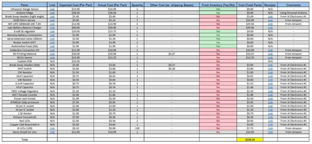
L1-9 Micro FOBO shall not exceed a cost of $250.00 to construct. Cost does not exceed $250.00 Inspection Pass
L2-2 Micro FOBO dimensions of robot will need to be small enough to fit in a 4in by 4in box for maze purposes. Micro FOBO fits in the 4in by 4in square of the maze. Inspection Pass

Detailed Success Criteria

This test case is successful if micro FOBO does not invalidate any of the requirements. Micro FOBO meets each of the requirements.

Test Environment

This test case will be taking place in ECS 316.

Assumptions and Preconditions

  • Micro FOBO is successfully built.

Procedure Steps

Step Number Step Description Pass Criteria Recorded Data Requirement(s) Tested Test Method
1 Carry micro FOBO to the cabinets and place it in one of the cabinets. Micro FOBO fits in the cabinet within those dimensions L1-5 Demonstration
2 View the cost report for micro FOBO and review the total cost. Micro FOBO’s cost does not exceed $250.00 L1-9 Inspection/Analysis.
3 Micro FOBO will be placed in one of maze squares. Micro fits inside of the 4in by 4in maze squares. L2-2 Inspection/Demonstration

Appendices

This section will contain any additional documentation needed to verify/validate requirements. For example, if a project has a cost constraint requirement, include the cost breakdown spreadsheet below as a subsection and reference the appendix subsection in the related Test Step in the Test Procedure. If another group needs to verify something by hand via calculation, include the calculations as a subsection below and reference the appendix subsection in the related Test Step in the Test Procedure.

  1. Print Time of FOBO
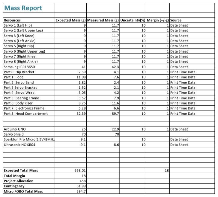
  2. Mass Report

Spring 2018: BiPed 3D Print Time

Written By: Miguel Gonzalez (Project Manager and Manufacturing)

Approved By: Miguel Garcia (Quality Assurance)

Update: 3D Printing Time Waiver (Approved on 5/01/2018)


Introduction

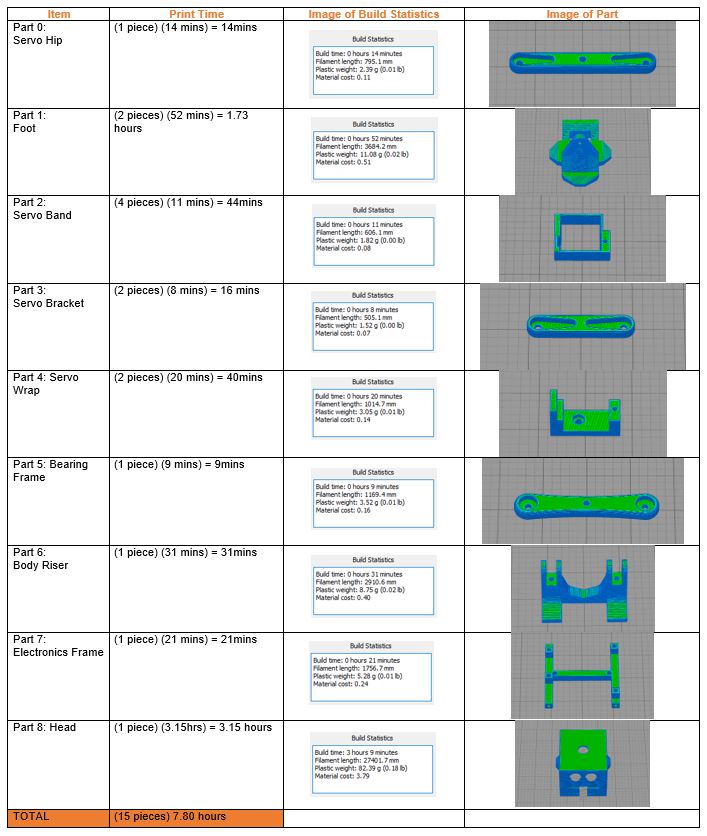
In this blog post, we will cover the overall 3D print time for the complete assembly of the Mirco FOBO. The Micro FOBO’s design is based on the original FOBO which was created by Jonathan Dowdall but utilizes updated and revised components. The design of the components will not be mention in this post but can be found in our Mechanical Design blog post. This post will explore the time it takes to manufacture parts for the Micro FOBO using a 3D printer. To better calculate the amount of time, use for fabrication I have created a table listing all the parts that are needed to assemble our robot and listed the time it takes to make it. Micro FOBO uses a total of fifteen 3D printed pieces which takes seven hours and forty-eight minutes. It is important to note that our current printing time violates our customer’s program requirement of keeping the printing time under 6 hours total. Only the head of FOBO exceeds the 2-hour limit of 3D printing requirement per part. Due to this violation, we have decided to appeal this requirement with a waiver document. By getting the approval of the customer through this appeal we won’t need to make any changes to our design or 3D printing process.

Related Requirements

Level 1 Requirements:

L1-8: Micro FOBO’s part components will be 3D printed using the material carbon fiber PLA.

L1-9: Micro FOBO will not exceed a print time of 7.80 hours. Upon approval of the waiver.

Level 2 Requirements:

L2-2: Micro FOBO dimensions will need to be small enough to fit in a 4in by 4in box for maze purposes.

L2-15: Micro FOBO shall weigh no more than the allocated mass of 460g.

Fig.1 Printing Times on Simplify3D

Table Data:

The table above shows Micro FOBO’s parts listed with their own “Build Statistics” which is information about the part’s printing time, weight, and cost of materials. This information was gathered through the slicing software, Simplify3D. All parts were listed to have a layer height of 0.20mm and 25% infill when producing the printing time information.

Final Remarks

It is important to note that the printing time shown above has been completely processed via slicing software but has been verified to be correct when printing the first full prototype. All 3D printing is done through my own 3D printer but the material (Carbon Fiber PLA) bought will be processed for reimbursement. As mentioned before, we currently exceed the amount of time allocated by the customer for printing time. The main reason we cross the six-hour mark is due to the head of FOBO requiring large amounts of support material and thus requiring more time to print out. We hope that the customer accepts our printing time waiver to allow us to keep the same head design and printing process.

References

Spring 2018: Testing Design Sketches

Written By: Miguel Gonzalez (Project Manager and Manufacturing Engineer)

Approved By: Miguel Garcia (Quality Assurance)


Table of Contents

Related Requirements

Level 1 Requirements

L1-3: Micro FOBO will have 2 legs.

L1-4: Micro FOBO will be a toy robot based on the design of the FOBO by Jonathan Dowdall.

L1-8: Micro FOBO’s part components will be 3D printed using the material carbon fiber PLA.

L1-11: Micro FOBO shall be 60% or less of the overall size of Jonathan Dowdall’s FOBO

Level 2 Requirements

L2-2: Micro FOBO dimensions will need to be small enough to fit in a 4in by 4in box for maze purposes.

L2-3: Micro FOBO will use SG90 micro servos.

Customer Requirements

C-03: The robot will be designed to be a toy for people ages 8+.

C-04: In order to minimize manufacturing cost, and packaging cost the robot shall be able to be constructed from sub assemblies within 10 minutes.

Before CAD

One of the first things we did when verifying our sketches was produced a copy of the original FOBO from www.projectbiped.com this would help in determining correct aspect ratios for the creation of the Micro FOBO. Using parts from previous semesters we managed to get all the necessary components to produce the FOBO. We 3D printed the parts for FOBO and assembled it all within the first three weeks of the semester.

Fig.1 Original FOBO Source: projectbiped.com

Fig.2 Printed FOBO


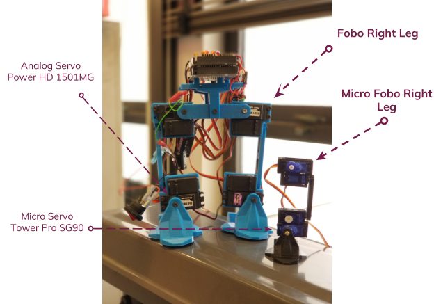
By using the printed out FOBO I was able to measure the individual parts of the robot and produce a scaled down version of each part. It mainly relied on using ratios of the larger servos compared to the micro servos our group planned on using. Figure 2 is an image that was taken after the testing of the micro FOBO parts but is a good illustration of the size comparison between the original  FOBO (in blue) and the Micro FOBO (in black).

Creating the 3D Models

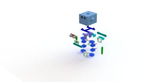
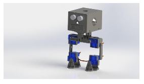
After creating the Initial Design Drawings on paper I made sure to 3D model the parts on Solid Works and test how the parts fitted together. Typically we can verify how the parts work together by using Solid Works Assembly and verifying the dimensions allow the parts to fit onto the micro servos and with one another. Of course, all parts first needed to be designed before we can verify part compatibility this also included designing the micro servos, ultrasonic sensor, and custom PCB. Below you will find 3D models of parts and components that were designed in Solid Works CAD.

Fig.3 3D Model of Micro Servos

Once all the parts were 3D modeled the first compatibility test on the parts was conducted by assembling all parts together using Solid Works. This process involved virtually assembling the Micro FOBO and verifying that all parts fit together properly and that all mounting holes aligned with each other.

Fig.4 Micro FOBO Exploded Assembly

Fig.5 Micro FOBO Full Assembly


Testing the 3D Models

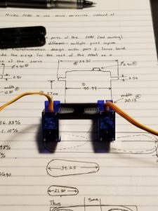
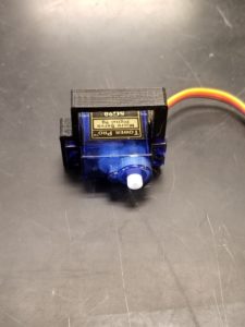
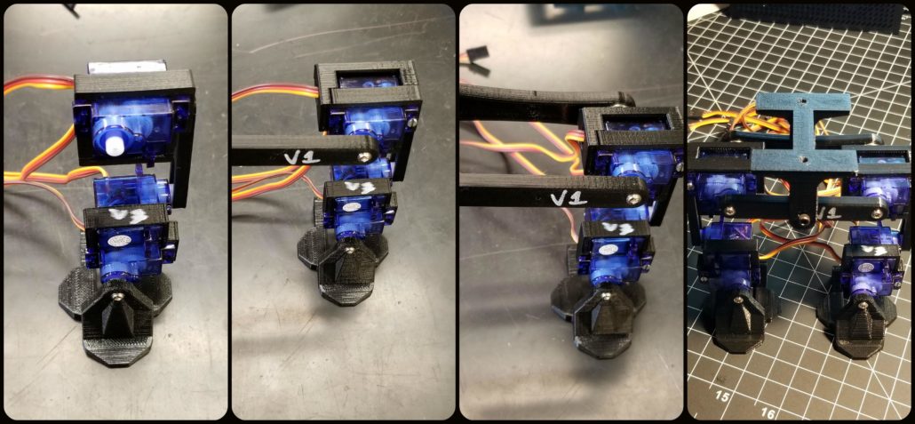
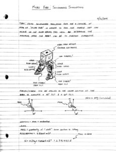
The last thing to do was to 3D print a prototype of the Micro FOBO and verify the results obtained from the assembly. Most parts that were printed out needed no revisions. Only the servo band and servo bracket required revisions. These parts typically required revising the mounting holes for the micro servos and slightly increasing the holes where the wires fitted through. Once the changes were applied to the model the parts were 3D printed again and verified that the issues no longer remained. We tested all designed parts by assembling a full-scale working prototype as shown below.

Fig.6 Part Verification

Fig.7 Testing Servo Fitting


Fig. 8 Part Verification with Sketches

Fig.9 Assembly Process

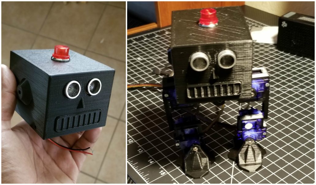
Fig.10 Head Verification and Assembly

References

  1. www.projectbiped.com
  2. Initial Design Drawings

Spring 2018: BiPed Initial Design Sketches

By: Miguel Gonzalez (Project Manager & Manufacturing)

Approved By: Miguel Garcia (Quality Assurance)


Related Requirements

Level One Requirements

L1-3: Micro FOBO will have 2 legs.

L1-4: Micro FOBO will be a toy robot based on the design of the FOBO by Jonathan Dowdall.

Level Two Requirements

L2-3: Micro FOBO will use SG90 micro servos.

L2-14: Micro FOBO shall measure within 4.5” x 3.25” x 7.25”.

Initial Sketches and Design

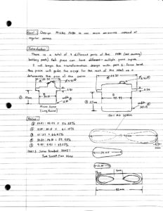
Since our robot was going to be based on the original FOBO created by Jonathan Dowdall we first needed to do some observation on his design. The original FOBO measured 24cm ( 9.5″) tall and 15.25cm ( 6″) wide. Because we are creating a miniature version of this design we can measure the servo size the original FOBO had with the micro servos we plan to use. As fig.1 shows, we can measure the two different servos and calculate their perspective ratio size with one another to give us an approximation of how small we can make our robot.

Fig.1 Calculating Ratio Sizes

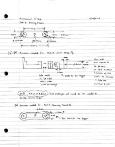
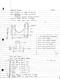
Various ratios were calculated from the measurements of the two servos and we discovered that our micro version of FOBO will be approximately 60% scale of the original FOBO. This is quite a significant reduction. Now that we had our ratios and measurements of the servos we could begin by sketching some of the FOBO parts and incorporate them to suit our miniaturized robot. The servo band and servo bracket were one of the first parts to be sketched and design since these parts attached the servos onto the FOBO’s leg. Measurements from the servos and the servo horns make up the dimensions of these parts. Since the micro servos were designed to be pressure fitted onto some of the parts small tolerances where only acceptable. It was made sure to only use datasheet measurements with verified dimensions from caliper measurements.

Fig.2 Sketches of Bearing Frame and Servo Wrap

Fig.3 Body Riser Sketches

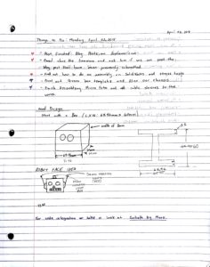
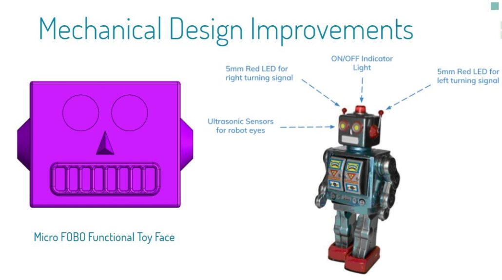
Many of the initial sketches have inaccuracies in their stated dimensions, this is due to the fact that testing and fast prototyping is needed to verify that the pieces would fit together. When designing the head of the robot it became evident that simply reducing its size by 60 percent of the original FOBO will not be sufficient. The head of micro FOBO is reliant on the size of the 3DoT board and the shield that will be mounted on it. Rough estimates on the dimension of the controller board were guessed in order to begin an initial sketching of the robot’s head. Once the head had been sketched it became evident that we can do some designs on its face to better meet the robot’s requirement of looking like a toy. This meant that we could use the ultrasonic sensors to look like eyes and thus we can design a nose and mouth to finish the face features. Antennas were also sketched on the head of the robot to simulate how toy robots looked like in the 1950s.

Fig.4 Head Sketches

Fig.5 Full Body Sketch

References

  1. http://www.projectbiped.com/prototypes/fobo
  2. 1950s Robot Toys

Spring 2018: BiPed Ultrasonic Sensor Board & Prototype Fritzing Diagram for BiPed

By: Jorge Hernandez (Electronics & Control Engineer)

Verified By: Miguel Gonzalez (Project Manager)

Approved By: Miguel Garcia (Quality Assurance)


Table of Contents

Introduction

From the research performed, the number of ultrasonic sensors required to make a biped
robot is one sensor. We know one sensor will be used which will cause the robot to only
detect objects in a one-directional plane. According to our level 2 requirements, we are using
the ultrasonic HC-SR04 sensor to meet out level two requirements:
Shall be able to see other robots to avoid a collision. The robot will stop completely and wait for
a command. (Ultrasonic sensor). This expands farther:
1. If the sensors are too far from an object, the robot will move forward.
2. If the sensors are too close to an object, the robot should move backward.
3. If the sensors are within the range of an object, the robot will not move.

Types of Ultrasonic sensors

Ultrasonic sensors have a range of 2-450cm (0.78-177in) which will be suitable to track the
other robots from 20 inches away. The way ultrasonic sensors operate is through emitting
sound waves and detecting the sound reflected back from the object. From the reflected
sound, the sensor can provide a measurement of how far an object is away from it. The pros of
ultrasonic sensors are that they can detect objects from farther distances and they can detect
small objects accurately. Also, they can operate in harsh conditions such as dirt. However, they
have slower response times than other sensors, their measurements can be distorted by loud
noises, and surfaces that absorb sound can deter their measurements. The dual cylinder
HC-SR04 is powered up through a 5V source, which will be suitable for our application because
we are using a 5V source coming through the I2C pins of the 3DoT board. The single cylinder
MaxSonar EZ1 Sensor can be powered through a 3V source, which will not be compatible with
our project. This makes the HC-SR04 Sensor the ideal ultrasonic sensor to use in our application.

Prototype Fritzing Diagram for BiPed:

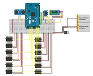
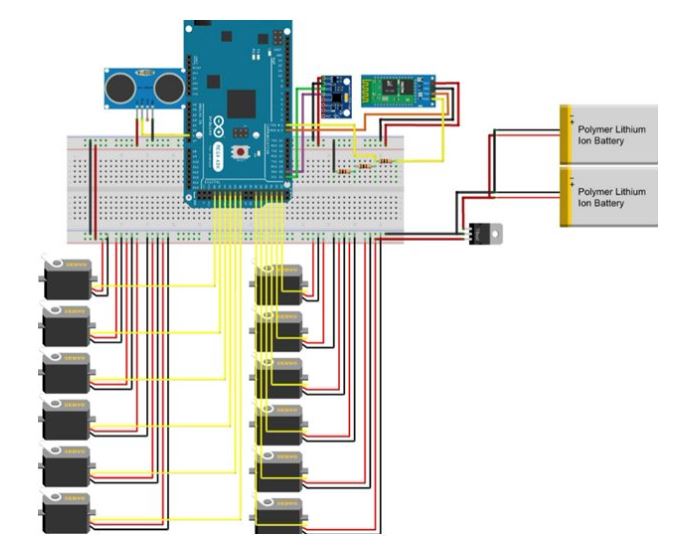
The Fritzing application allows a physical breadboard design to be created digitally. By designing
a digital version, the beginning PCB designs can begin. One difficulty with using the free
software is that the library does not have all the parts needed for many designs. Using Google,
many of the parts required were found with Github.
Here are links to the Fritzing libraries for FOBO:
(If using the Adafruit Servo Driver)
(For the Bluetooth Module HC-06 and Accelerometer/Gyroscope MPU-6050)

Fig.1 Electronic Fritzing Diagram


There was nothing to change at all as we are using the FOBO’s same hardware build. We decided
to go with 2 Lithium Ion batteries, 12 servos, and ultrasonic as well. The color sensor is being
discussed since we know Spiderbot wants to use UV sensors but will be added to fritz diagram
once we know the final maze descriptions.

References

Updated Here: Blog Post

Spring 2018: BiPed Power Estimates of Components: Micro Servos

By: Jorge Hernandez (Electronics & Control Engineer)

Verified By: Miguel Gonzalez (Project Manager)

Approved By: Miguel Garcia (Quality Assurance)


Table of Contents

Power Estimates 

For power estimates I calculated power and current on two types of servos; the Tower Pro SG90 and metal geared MG90s. To read the power and current from the servos on different loads, I used the INA219 current sensor. A 3-D pully was made and connected on top of the servos as Professor Hill suggested.

Fig.1 Testing Environment

Coding

I combined the Sweep Arduino code with an Arduino code to read the current and power from the INA219 current sensor. I used a function ‘read values’ to act as the INA219 sensor and embedded it within the for loop which had the servo turn back and forth 180 degrees which are known as the sweep code for servos. Here it will read the values every 5 degrees to get an accurate reading.

/* Sweep

 by BARRAGAN <http://barraganstudio.com>

 This example code is in the public domain.

 modified 8 Nov 2013

 by Scott Fitzgerald

 http://www.arduino.cc/en/Tutorial/Sweep

*/

#include <Servo.h>

#include <Wire.h>

#include <Adafruit_INA219.h> // You will need to download this library

Adafruit_INA219 sensor219; // Declare and instance of INA219

Servo myservo;  // create servo object to control a servo

// twelve servo objects can be created on most boards

int pos = 0;    // variable to store the servo position


void setup() {

  myservo.attach(9);  // attaches the servo on pin 9 to the servo object

  Serial.begin(9600);    

  sensor219.begin();

}

void ReadValues ()

{

   float busVoltage = 0;

  float current = 0; // Measure in milli amps

  float power = 0;

  busVoltage = sensor219.getBusVoltage_V();

  current = sensor219.getCurrent_mA();

  power = busVoltage * (current/1000); // Calculate the Power

//  Serial.print("Bus Voltage:   "); 

//  Serial.print(busVoltage); 

//  Serial.println(" V");  

  Serial.print("Current:       "); 

  Serial.print(current); 

  Serial.println(" mA");

  Serial.print("Power:         "); 

  Serial.print(power); 

  Serial.println(" W");  

  Serial.println(""); 

  }

void loop() {

  for (pos = 0; pos <= 180; pos += 1) { // goes from 0 degrees to 180 degrees

    // in steps of 1 degree 

    if (pos%10==0)

    {

    ReadValues ();

    }

    myservo.write(pos);              // tell servo to go to position in variable 'pos'

    delay(15);                       // waits 15ms for the servo to reach the position

  }

  for (pos = 180; pos >= 0; pos -= 1) { // goes from 180 degrees to 0 degrees

    if (pos%10==0)

    {

    ReadValues ();

    }

    myservo.write(pos);              // tell servo to go to position in variable 'pos'

    delay(15);                       // waits 15ms for the servo to reach the position

  }

}

Results

Table 1: SG90(plastic Micro-servo) @ 3.3 V

Table 2: MG90 (metal Micro-servo) @ 3.3 V

Table 3: SG90(plastic Micro-servo) @ 5V

Table 4: MG90(metal Micro-servo) @ 5 V

Conclusion

SG90 Plastic Geared will be used for Micro Fobo as it satisfies more requirements than the MG90 metal geared micro servo. The SG90 also pulls less current at different loads.  Both micro servos operate at 3.3V (L2-7: Micro FOBO shall use a battery that outputs 3.7V) but as can be seen, the MG90 stalls with a load of 200 grams. Satisfies customer requirement as it is toy based and will have a cleaner look as they are small and fit well on the chassis.

References

  1. https://www.arxterra.com/spring-2016-velociraptor-servos/
  2. https://www.arxterra.com/servo-trade-off-study/

Spring 2018: BiPed Interface Matrix

By: Jeffrey De La Cruz (Mission, Systems, and Test Engineer)

Verified By: Miguel Gonzalez (Project Manager)

Approved by: Miguel Garcia (Quality Assurance)


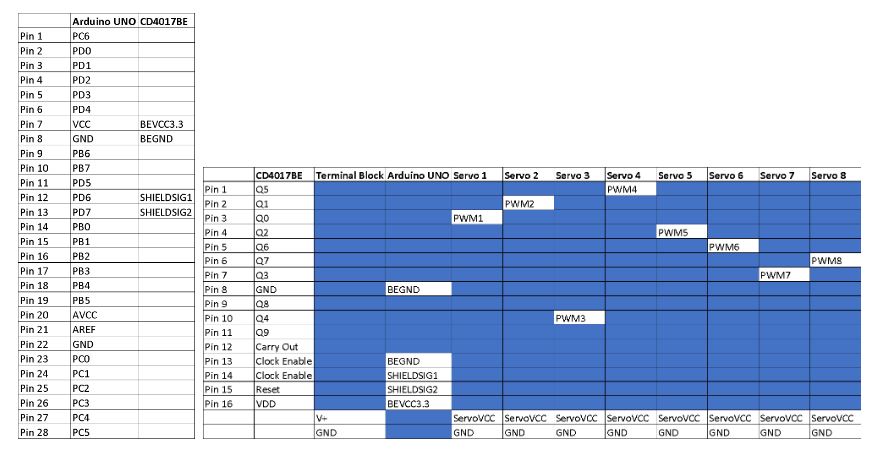
Fig.1 Interface Matrix

The current interface matrix for the prototype Micro FOBO uses the Arduino UNO. A CD4017BE IC was used in order to control the eight servos. The output of the CD4017BE IC was then connected to the Arduino UNO which will the Robot Poser control the movement of the servos so that the Micro FOBO can walk. The interface matrix will be updated once the 3DoT board or the Sparkfun Pro Micro 3.3V/MHz is acquired. This is currently for the prototype of the Micro FOBO.
The excel file containing the interface matrix for the prototype Micro FOBO can be found

Spring 2018: Interface and Cable Tree Blog Post

By: Jorge Hernandez (Electronics & Control Engineer)

Verified By: Miguel Gonzalez (Project Manager)

Approved by: Miguel Garcia (Quality Assurance)


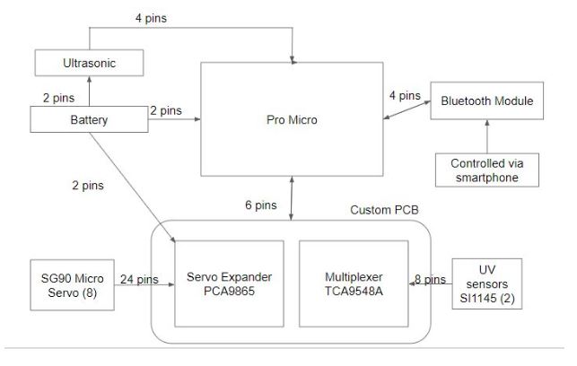
New and improved System Block Diagram for Micro Fobo which shows in a general diagram how many pins will be needed for each component and how they connect to each other. As seen we are using a total of 5 sensors, a custom PCB, Bluetooth module, external battery and of course a Pro Micro. This helps a lot for our E&C engineer when it comes to PCB designing as they need to plan accordingly.

Fig.1 Micro FOBO System Block Diagram

Wiring Management

No Exposed Wires;

Wiring for sensors, Pro Micro, and PCB will not be exposed and will all be within the head of Micro Fobo.

Exposed Wires:

1/8 Inch PET Expandable Braided Sleeving with quarter inch heat shrink tubing will be used on the wires that connect the micro servos to the header

  • Used to cover the wires of the SG90 micro servo
  • Ensures complete coverage and protection of wires
  • Clean design

The cables for the servos are routed out of the head encasement and directly to the servos through the back of Micro Fobo. Below is a photo of how clean Micro Fobo will look.

Fig.2 Micro FOBO full Assembly

References

  1. https://www.arxterra.com/spring-2017-spiderbot-cable-tree-design/

Spring 2018: BiPed Ultrasonic Sensor Board Power Test

By: Jorge Hernandez (Electronics & Control Engineer)

Verified By: Miguel Gonzalez (Project Manager)

Approved by: Miguel Garcia (Quality Assurance)


Table of Contents

Introduction

From the research performed, the number of ultrasonic sensors required to make a bi-ped robot for our project is one. We know one sensor will be used which will cause the robot to only detect objects in a one-directional plane which will act as the eyes of the robot. We are using the ultrasonic HC-SR04 sensor to meet our level two requirements:
Shall be able to see other robots to avoid a collision. The robot will stop completely and wait for a command. (Ultrasonic sensor). This expands further:
1. If the sensors are too far from an object, the robot will move forward.
2. If the sensors are too close to an object, the robot should move backward.
3. If the sensors are within the range of an object, the robot will not move.

Choosing our Ultrasonic

For economical reason, we chose to go with the SEN136B5B ultrasonic sensor as the previous Biped Robot from spring 17’ had left thiers with Professor Hill (along with other parts); L1-8: Micro FOBO shall not exceed a cost of $200 to construct. Although there are more precise sensors all we needed was a sensor to provide a measurement of how far an object is away (3cm-400cm) which the Sen136B5B does well. Another reason why we chose this ultrasonic is to satisfy requirement L1-4: Micro FOBO will be a toy robot based on the design of the FOBO, which make it seem as the eyes of Micro Fobo.

Power Estimates

Due to the fact, the  3DoT board we are using has a 3.3V input is another huge reason we are using the SEN136B5B as it functions at 3.3V, unlike the HC-SR04. We could have used the HC-SR04 but to save space we eliminate the idea of a booster shield which will allow us to use this sensor and other 5V sensors if needed. The global current consumption was very hard to test as it only draws 15 mA according to http://wiki.seeedstudio.com/Ultra_Sonic_range_measurement_module/ which is very low and did not give me a reading when I attached it to a current sensor which would’ve given me the power estimates of this ultrasonic.


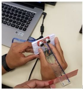
Fig.1 Ultrasonic 6in Test

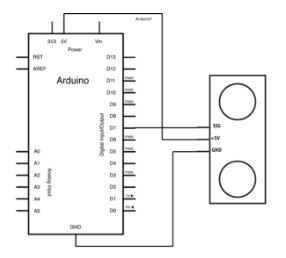
Fig.2 Ultrasonic Connections


This sketch reads a PING))) ultrasonic rangefinder and returns the distance to the closest object in range. To do this, it sends a pulse to the sensor to initiate a reading, then listens for a pulse to return. The length of the returning pulse is proportional to the distance of the object from the sensor.

The circuit:

  •     +V connection of the PING))) attached to +5V
  •     GND connection of the PING))) attached to ground
  •     SIG connection of the PING))) attached to digital pin 7

Wiring & Code

*/

// this constant won't change. It's the pin number of the sensor's output:

const int pingPin = 7;

voidsetup() {

  // initialize serial communication:

  Serial.begin(9600);

}

voidloop() {

  // establish variables for duration of the ping, and the distance result

  // in inches and centimeters:

  long duration, inches, cm;

  // The PING))) is triggered by a HIGH pulse of 2 or more microseconds.

  // Give a short LOW pulse beforehand to ensure a clean HIGH pulse:

  pinMode(pingPin, OUTPUT);

  digitalWrite(pingPin, LOW);

  delayMicroseconds(2);

  digitalWrite(pingPin, HIGH);

  delayMicroseconds(5);

  digitalWrite(pingPin, LOW);

  // The same pin is used to read the signal from the PING))): a HIGH pulse

  // whose duration is the time (in microseconds) from the sending of the ping

  // to the reception of its echo off of an object.

  pinMode(pingPin, INPUT);

  duration = pulseIn(pingPin, HIGH);

  // convert the time into a distance

Fig.3 Ultrasonic Test#2

Power Estimates Continued

We choose to go with the Seed Ultrasonic Sensor (SEN136B5B ) as it is 3.3V compatible, the sensor was available from previous biped projects, and to meet requirements for our project which were explained above. This 3 pin ultrasonic requires power, Gnd, and a digital pin has an operating current of 15 mA and can read up to 400cm as tested.

Fig.2 Part 1 Power Estimates Table


Fig.2 Part 2 Power Estimates Table

Conclusion

We choose to go with the Seed Ultrasonic Sensor (SEN136B5B ) as it is 3.3V compatible, the sensor was available from previous biped projects, and to meet requirements for our project which were explained above. This 3 pin ultrasonic requires power, Gnd, and a digital pin has an operating current of 15 mA and can read up to 400cm as tested.

References

  1. https://www.arxterra.com/tracking-sensors-trade-off-study/
  2. http://www.arduino.cc/en/Tutorial/Ping
  3. http://wiki.seeedstudio.com/Ultra_Sonic_range_measurement_module/

Spring 2018: BiPed Preliminary Design Documentation

By: Miguel Gonzalez (Project Manager), Jeffery De La Cruz (MST), Jorge Hernandez (E&C)

Approved by: Miguel Garcia (Quality Assurance)


Table of Contents

Mission Objective

By: Miguel Gonzalez (Project Manager & Manufacture)


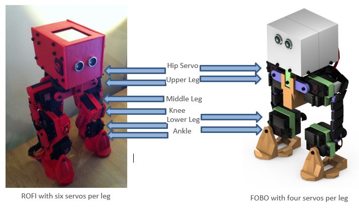
Our goal for this project is to design and manufacture a BiPed Robot. This robot will be slightly similar to the BiPed robot that was created in Spring 2016 and another bipedal robot named FOBO, created by Jonathan Dowdall. Our design will be based on FOBO but will be much smaller in size that implements micro servos for walking and turning. For sensing its surroundings, the robot will utilize ultrasonic and Infrared sensors. Other key differences between the FOBO and our micro version of FOBO are that:

  1. The head of our robot shall house a 3DoT board, servos controller shield, and a sensor shield.
  2. The movement of our robot will be conducted via SG90 micro servos that will replace the clunky and oversized Hitec HS-805BB servos.
  3. The legs of our robot will have a more efficient method to mount and utilize its servos for weight reduction and for longer walking steps.
  4. Our robot will utilize Bluetooth technology for user to robot communication and movement control
  5. The robot’s power system will be changed from heavy LIPO batteries to a single Samsung 18650 battery located near the robot’s center of mass.

The mission of Project BiPed is to design the BiPed to navigate a predesigned maze. The BiPed shall be able to navigate the maze with user input from the Arxterra App/Control Panel. The BiPed will be able to memorize the user-defined path and will be able to navigate it autonomously. In addition, the BiPed will acknowledge other robots while traversing the maze and avoid collisions using its sensors. To learn more about the mission objective you can take a look here. For preliminary maze designs and definitions take a look here.

Project: Level 1 Requirements

By: Jeffery De La Cruz (MST Engineer)

Verified By: Miguel Gonzalez (Project Manager)


Will:

L1-1: Micro FOBO will stand on its own without any physical help.

L1-2: Micro FOBO’s electronic components will be easily assembled and disassembled.

L1-3: Micro FOBO will have 2 legs.

L1-4: Micro FOBO will be a toy robot based on the design of the FOBO by Jonathan Dowdall.

L1-6: Micro FOBO will fit within the classroom cabinets shelves. 28”x13”x14.5”

L1-7: Micro FOBO will utilize a 3DoT board or Sparkfun Pro Micro 3.3V/8MHz.

L1-8: Micro FOBO’s part components will be 3D printed using the material carbon fiber PLA.

L1-9: Micro FOBO will not exceed a print time of 7.80 hours. Upon approval of the waiver.

Shall:

L1-10: Micro FOBO shall not exceed a cost of $250 to construct.

L1-11: Micro FOBO shall be 60% or less of the overall size of Jonathan Dowdall’s FOBO

L1-12: Micro FOBO shall detect intersections in the maze.

L1-13: Micro FOBO shall be able to perform static walking.

L1-14: Micro FOBO shall produce 90 degrees turn.

L1-15: Micro FOBO shall be guided through the maze with the use of the Arxterra application.

L1-16: Micro FOBO shall record the path of the maze.

L1-17: The Micro FOBO shall traverse the maze using the recorded path.

L1-18: Micro FOBO shall be able to traverse cloth, paper, and linoleum materials.

L1-19: The Final Biped shall be completed by May 10th, 2018.

Should:

L1-20: Micro FOBO should step over a square rod 1cm tall, 1 cm wide by 10 cm long

L1-21: Micro FOBO should be able to perform dynamic walking

System/Subsystem: Level 2 Requirements

By: Jeffery De La Cruz (MST Engineer)

Verified By: Miguel Gonzalez (Project Manager)


Will:

L2-1: Micro FOBO will be connected via Bluetooth to the app on an android phone.

L2-2: Micro FOBO dimensions of the robot will need to be small enough to fit in a 4in by 4in box for maze purposes.

L2-3: Micro FOBO will use SG90 micro servos.

Shall:

L2-4: Micro FOBO shall use UV/IR sensors to detect intersections.

L2-5: Micro FOBO shall use the color of the maze to establish if it needs to turn. black (0,0,0) green (0,255,0) for line following.

L2-6: Micro FOBO shall use a battery that outputs 3.7V nominal.

L2-7: The user shall use the Arxterra application to move the robot forward, backward, left, and right.

L2-8: Micro FOBO connectors shall be able to connect and reconnect all the wiring in less than 10 min.

L2-9: Micro FOBO wiring shall be nice and clean with the use of terminal blocks, contact pins, 2.0mm PH series JST connectors, and barrel connectors.

L2-10: Micro FOBO shall play a musical tune when the maze is completed.

L2-11: Micro FOBO shall have indicating LEDs to demonstrate either a left or right turn.

L2-12: The Micro FOBO shall record the path of the robot on the 3DoT board or the Sparkfun Pro Micro 3.3V/8MHz to navigate the robot through the maze.

L2-13: Micro FOBO shall use a 3D printed chassis and leg components.

L2-14: Micro FOBO shall measure within 4.5” x 3.25” x 7.25”.

L2-15: Micro FOBO shall weigh no more than the allocated mass of 460g.

L2-16: Micro FOBO shall detect objects 8 inches from it.

Should:

L2-17: Micro FOBO should be able to see other robots to avoid a collision. The robot will stop completely and wait for clearance. (Ultrasonic sensor)

L2-18: Micro FOBO should take a bow at the end of the maze as a victory celebration.


System Block Diagram

By: Jorge Hernandez (E&C Engineer)

Verified By: Miguel Gonzalez (Project Manager)


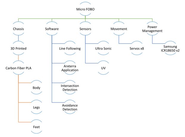
After looking at all the constraints and requirements for the robot our group came up with a system block diagram that could help us visualize how the robot’s components interacted with one another. This diagram made it clear to understand where initial designs should be made and provided great insists to some challenges we would have in the future. For example, we can see the product breakdown structure down below and notice that our robot’s chassis contains more sub-branches than the rest of the diagram sibling branches. This indicates that most of the designing will be involved in the creation of the robot’s main hardware. This would help our manufacturing engineer know that designing of the robot’s chassis should be done as early as possible to prevent set back. Another branch that stands out is the software section. This branch is made up of multiple sections that include Arxterra control, line following, avoidance detection, and turning code. This branch is important as the diagram illustrates that our robot is highly dependent on its software to achieve a successful mission objective.
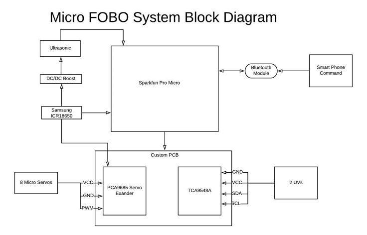
Fig.1 System Block Diagram

Work Breakdown Structure

By: Miguel Gonzalez (Project Manager & Manufacture)


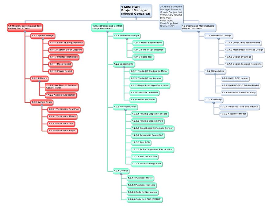
Once we had a clear idea of how the robot would be made we proceed to create a WBS. A work breakdown structure allows us to list and assign tasks/work that needs to be completed for the success of the robot. The tasked listed on the WBS based on the team member’s job description and are directly imported from the tasks created on the Spring 2018 Task Matrix that can be found here. The diagram below is a much easier method of reading the tasked matrix as it clearly shows each team member’s responsibilities.

Our group consists of three members fulfilling the roles of Project Manager, E&C, MST, and Manufacturing Engineer. Since the group has fewer members than the positions available the manufacturing role of the team was given to the Project Manager.

The diagram below shows the workload of the project and how it is distributed among the team. It is based on the job descriptions and shows major tasks that each person is responsible for. We will be taking a look at each team members role more closely to better understand the structure of the team and its workload.

Fig.2 BiPed Work Breakdown Structure

Miguel Gonzalez (Project Manager)

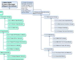
Fig.3 PM and Manufacturing Engineer Tasks (Blue)

At the top of the WBS in blue, we have the project manager section. Note that in our case the project manager is also the manufacturing engineer and thus the tasks for both roles are given to the same person. The second blue icon shows the tasks specific to the project manager which has the project manager responsible for the following tasks:

  • Creating and managing schedule
  • Creating a budget list
  • Creating the preliminary report
  • Creating the final blog post
  • Creating project video
  • Define Work Breakdown Schedule

The manufacturing tasks given to the project manager are listed to the right side of the WBS also in blue. These tasks are broken down into three sections Mechanical Design, 3D Modeling, and Assembly. These sections were created based on which tasks are needed to be done before moving on to the next section. For example, Mechanical Design is a prerequisite for 3D Modeling and Assemble thus it is located on top of the other tasks.

Jeffery De La Cruz (MST)

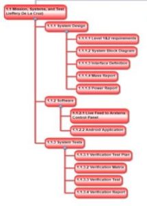
Fig.4 MST Tasks (Red)

Moving on to the left side of the WBS (in red), we have all the tasks assigned to the MST engineer. Once again, these tasks are divided up into three sections System Designs, Software, and System Tests. The system designs include tasks that have a focus on research and trade studies that will end up helping with the software development and system test. Once those tasks are done the MST engineer can proceed with implementing the software with the Arxterra control panel and onto an android application. The final tasks for the MST engineer focus on verifying and testing all sections of the robot to see if they are operational.

Jorge Hernandez (E&C)

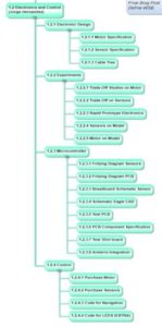
Fig.5 E&C Tasks (Green)

The final branch in the WBS applies to the E&C engineer and his tasks needed for a successful project. The E&C has the greatest responsibility for the success of the robot becoming operational. His roles are divided into 4 categories Electronics Design, Experiments, Microcontroller, and Control. These categories cover a wide range of tasks that need to be realized to proceed with the overall goal of the Biped project.

Product Breakdown Structure

By: Jeffery De La Cruz (MST Engineer)

Verified By: Miguel Gonzalez (Project Manager)


Fig.6 Product Breakdown Structure

Based on System Block

Sensor Suite

  • The color sensor will be able to detect colors and its data input range Ex, black (0,0,0) green (0,255,0) for line following.
  • Will be able to see intersection sign on the maze and differentiate its color from the path lines.
  • Shall be able to see other robots to avoid a collision. The robot will stop completely and wait for a command. (Ultrasonic sensor/IR)
  • The robot should have to indicate LEDs to show where the robot plans to make a turn (left or right)

Smartphone App

  • Will allow usage of the app to navigate the robot through the maze through forward, back, left, and right commands.
  • Will record the path of the robot in 3Dot board to navigate robot without the user controlling it.
  • The robot will be connected via Bluetooth to the app on an android phone.

Chassis

  • The wiring for the robot shall be nice and clean with the use of terminal blocks, contact pins, 2.0mm PH series JST connectors, and barrel connectors.
  •  All connectors shall be able to connect and reconnect all the wiring in less than 5 min.
  • Dimensions of the robot will need to be small enough to fit in a 6in by 6in box for maze purposes.

Battery

  • The robot power management system will use two 1000mAh 2S 20C Lipo Pack rechargeable LIPO batteries.

Interface Matrix

By: Jeffery De La Cruz (MST Engineer)

Verified By: Miguel Gonzalez (Project Manager)


Fig.7 Interface Matrix

The current interface matrix for the prototype Micro FOBO uses the Arduino UNO. A CD4017BE IC was used to control the eight servos. The output of the CD4017BE IC has then connected the Arduino UNO which will the Robot Poser control the movement of the servos so that the Micro FOBO can walk. The interface matrix will be updated once the 3DoT board or the Sparkfun Pro Micro 3.3V/MHz is acquired. This is currently for the prototype of the Micro FOBO. The excel file containing the interface matrix for the prototype Micro FOBO can be found here.

Prototype Fritzing Diagram for Biped

By: Jorge Hernandez (E&C Engineer)

Verified By: Miguel Gonzalez (Project Manager)


The Fritzing application allows a physical breadboard design to be created digitally. By designing a digital version, the beginning PCB designs can begin. One difficulty with using the free software is that the library does not have all the parts needed for many designs. Using Google, many of the parts required were found with Github.

Here are links to the Fritzing libraries for FOBO:

(If using the Adafruit Servo Driver)

https://github.com/adafruit/Fritzing-Library

(For the Bluetooth Module HC-06 and Accelerometer/Gyroscope MPU-6050)

https://github.com/RafaGS/Fritzing

Fig.8 Electronic Fritzing Diagram

There was nothing to change at all as we are using the FOBO’s same hardware build. We decided

to go with 2 Lithium Ion batteries, 12 servos, and ultrasonic as well. The color sensor is being

discussed since we know Spiderbot wants to use UV sensors but will be added to fritz diagram

once we know the final maze descriptions.

References

Spring 2016 ROFI

Spring 2017 Velociraptor

Updated Fritzing

Mechanical Drawings

By: Miguel Gonzalez (Project Manager & Manufacture)


Related Requirements

Level One Requirements

L1-3: Micro FOBO will have 2 legs.

L1-4: Micro FOBO will be a toy robot based on the design of the FOBO by Jonathan Dowdall.

L1-11: Micro FOBO shall be 60% or less of the overall size of Jonathan Dowdall’s FOBO

Level Two Requirements

L2-2: Micro FOBO dimensions will need to be small enough to fit in a 4in by 4in box for maze purposes.

L2-14: Micro FOBO shall measure within 4.5” x 3.25” x 7.25”.

Micro FOBO Design

For some clarification and for better understanding our design of the Micro FOBO, I have created a color-coded assembly of the robot with matching titles indicating the names of each component. Below I discuss the design of these components that make up the Micro FOBO.

Fig.9 Micro FOBO Colored Parts

As you can see from the image above, the Micro FOBO consist of 9 different parts: Servo Hip, Foot, Servo Band, Servo Bracket, Servo Wrap, Bearing Frame, Body Riser, Electronics Frame, and the Head. Note that Micro FOBO can be made up of multiple copies of the same part component and thus colored coded with the same color. For example, there are four servo bands in Micro FOBO which are shown in light green on the picture. Now that we know which parts make up the robot we can begin looking at the design of each part individually.

Part 0: Servo Hip

Fig.10 Part 0: Servo Hip

The “Servo Hip” component of the Micro FOBO is responsible for attaching the two upper micro servos which are the hip servos. This bracket connects both servos (right and left legs) together to act as a hip bone that allows the robot to move its legs left to right. The connection to the servos is made via servo horns that are provided by the manufacturer. This part has two allocated trenches that match the dimensions of the servo horns allowing the servos to mount to the part. The horns are then screwed onto the servo hip using M2.5 screws that are 8mm in length.

Drawing File

Part 1: Foot

Fig.11 Part 1: Foot

The “Foot” component is the same for both legs and is a simple shoe like design with wide pads on its sides. The extra material on the sides allows a greater amount of surface to touch the floor allowing the robot to balance easier. Currently, this part is in its simplified state as there is not much detail design put on it. This is because the team plans on mounting UV sensors onto the bottom of the foot where the hole is located. This would allow the sensor to be as close to the ground as possible to maintain an accurate reading. Once we receive the sensor additional design changes will be made to this part. Currently, the part allows the ankle servo, which is the servo closest to the ground, to be mounted onto one side of the foot though servo horn cutouts. The horn cutout is located on the inside wall of the part. The hole then allows an M2.5 X8 screw to secure the servo onto the foot piece.

Drawing File

Part 2: Servo Band

Fig. 12 Part 2: Servo Band

There is a total of four “Servo Bands” located on the Micro FOBO. This part is responsible for grouping two micro servos together which forms a section of a leg. The two servos are pressure fitted into the square cutout and thus this part must be dimensionally precise to prevent servos to come loose. This piece had several revisions to satisfy the dimensional accuracy need to keep the servos secure. The servos were measured with a caliper and the thickness of the servos stickers even had to be considered when designing this piece. Due to leg movement constraints, only one servo can have extra material to be screwed onto the part.

Drawing File

Part 3: Servo Bracket

Fig.13 Part 3: Servo Bracket

The ‘Servo Bracket” is a shorter version of part 0: servo hip and serves a similar purpose. This component mounts onto two servos that are located on the servo bands. This allows the second to the top servo to move the lower leg. This piece is located in the middle of the leg and connects the top and lower sections. This piece can be thought as the knee of the robot. Just like the other brackets, there are two cutout trenches that allow servo horns to be mounted and secured through a single screw. This piece can be varied in length to adjust the height of the robot and adjust the walking stride of the robot itself.

Drawing File

Part 4: Servo Wrap

Fig.14 Part 4: Servo Wrap

The “Servo Wrap” is a small piece that attaches the back of the hip servo (top leg servo) to be mounted onto part 5: Bearing Frame. It is connected via an M2 screw that is 18mm in length. The screw goes through the servo, through the servo band, and screws into this piece. A hole on the left side of the wall was added to allow the servo wires to feed through and connect back to the electronics. Notice there is a hexagon trench located near the middle of the part. This trench allows an M3 nut to be placed in that location and lets a screw to secure Part 4 with Part 5. Another key design feature is the chamfer cutout located on the backside of the part. This permits higher degrees of movement from the hip servos by at least 45 degrees more.

Drawing File

Part 5: Bearing Frame

Fig.15 Part 5: Bearing Frame

The “Bearing Frame” is a mirror-like component to part 0 as both pieces work together to provide the connection of legs to body. One of the key differences is that this piece contains two large circular trenches in which a bearing can fit onto. Using a 10mm circular bearing we place it on the part to provide free angular movement to the left and right sides of the pieces. Once the bearings are fitted inside, we can use M3X14 bolts to attach the servo wrap pieces to the left and right side of the Bearing Frame. Since the legs servos are already attached to the servo wrap we effectively attached the two legs to the body of the robot.

Drawing File

Part 6: Body Riser

Fig.16 Part 6: Body Riser

Micro FOBO mainly consists of a head and two legs but this part, body riser, can be considered the body of the robot. This component connects the two attached legs with the head. There are two fork-like structures located at the top of the piece that allows part 0 and part 5 to fit in snugly effectively connecting the two legs to this piece. Part 0 and part 6 are secured through a couple of M3 screws with an approximate length of 16 mm. The back side of this component is flat and has two holes for connecting to part 7 which is the electronics frame. The body riser can be increased in height allowing the robot’s head to be located higher above the legs. We can experiment with changing the height to allow shifting the robot’s center of mass higher or lower as needed.

Drawing File

Part 7: Electronics Frame

Fig.17 Part 7: Electronics Frame

The Electronics Frame is a thin component that is responsible for connecting the PCB to the body riser. The PCB will contain four mounting holes which will allow the board to connect to this part. Note that the part contains extruded cubes that correspond to the location of the PCB hole mounts. These extruded cubes also have a hole cut out to fit M3 screws that secure the board in place. Finally, the part can be secured to the head via similar M3 screws on the side of the part and head

Drawing File

Part 8: Head

Fig.18 Part 8: Head

One of the first challenges in creating a miniature FOBO we observed was that our robot would need to support large amounts of electronic components that used to be on the regular size FOBO. These electronics would need to be smaller in size or our head design would need to optimize to fit all the electronics. Our first design was based on the prediction that the new electronics would have a smaller footprint and thus the head of the Micro FOBO is much smaller. The exact dimensions can be found on the link below. Once the size of the head was set I began to look at some redesigns that I can implement to change the look and functionality of the robot’s head. That is when I stumbled on an image of a tin toy robot from the 1950s.

Fig.19 1950’s Tin Toy

As you can see from the image above this robot has a similar head as the FOBO which gave me the idea of emulating the design of the face. The ultrasonic sensor will take place as the robot’s eyes and the mouth and nose features would simply be aesthetics. Another thing that I noticed was that the tin toy contained antennas on the left and right side of the head. One of the redesigns I wanted to incorporate since the beginning was adding turn signals to the robot and the antennas can certainly be used for that. My idea is to have small 5mm red LED’s as the tip of the antennas that would blink indicating when the robot will turn and in what direction. Finally, we see that there is a small red light on top of the robot that can be designed to indicate on/off status of the robot.

Fig.20 Mechanical Design Improvements

Drawing File        Tin Robot Toy

Resource Reports (Power, Mass, Cost)

By: Jeffery De La Cruz (MST Engineer)

Verified By: Miguel Gonzalez (Project Manager)


Below are the preliminary resource reports for the mass, power, and cost for Project BiPed. As we continue working on Project BiPed, the resource report will be updated to the actual numbers of each mass, power, and cost.

Fig. 21 Mass Report

The total mass of the Micro FOBO is at around 351.5 grams. This mass consists of the following:

Part 0: Hip Bracket x1

Part 1: Foot x2

Part 2: Servo Band x4

Part 3: Servo Bracket x2

Part 4: Servo Wrap x2

Part 5: Bearing Frame x1

Part 6: Body Riser x1

Part 7: Electronics Frame x1

Part 8: Head Compartment x1

Micro Servos x8

Samsung ICR18650 x1

Arduino UNO x1

Servo Shield x1

Ultrasonic HC-SR04 x1

To view the excel file of the mass report, click here.


The mass of the Micro FOBO will change because the material used to print the parts of the Micro FOBO will change from regular PLA to carbon fiber PLA. The Micro FOBO will become just lighter but not by much. The mass of the Arduino UNO and servo shield is included at the moment but will be updated once the 3DoT Board of the Sparkfun Pro Micro 3.3V/8MHz is included. Also, the battery case was not included because the position of the battery is to be determined.

Fig.22 Power Report

Cost Report

By: Miguel Gonzalez (Project Manager & Manufacture)


Related Requirement

L1-10: Micro FOBO shall not exceed a cost of $250 to construct.

Project BiPed is one of this semesters robot production division in which a bipedal robot will be designed, engineered, and produced by the end of the semester. One of the most important tasks of any project is to evaluate and determine the cost of production of said products. In this post, we will be looking at the estimated cost of producing the BiPed robot. These costs will solely rely on physical component cost and any design and research development cost will not be mentioned in this post.

As part of the requirements stated by the customer, a budget was set for each project divisions. This is a loosely budget of $250 in which all material bought can be reimbursed in full. Any additional items and/or services that exceeded this budget will be covered by the team members working on the project. To help reduce costs, the customer has allowed access to his lab stock inventory of electronics, hardware, and materials. Borrowed items will be included in the budget table but the costs of the items will not be included in the total money spent.

Fig.23 Spring 2018 BiPed Budget Table

Budget Table (for access to links found on the table)

The above table shows the cost of components we have used and purchased as of April 18, 2018. The budget table above is divided into ten separate columns indicating important information about the used and purchased products. In the left column are the names of the parts and items used by the team to produce the biped robot. To the right of the parts column, is a link section that allows viewers to find the same parts we used for this project online. The table is also set up for invoice collection for any items that were purchased these invoices/receipts are linked on the second column to the right of the table. The budget table tries to incorporate all useful information that may be needed for future part purchases, replacement of parts, and for reimbursements.

Overall, we wanted to make sure not to spend any unnecessary money and to reuse as many electrical components and hardware as we could. It is important to note that some additions to the table will be made as the project continues and more items are needed. Multiple hours of reading past blogs as well as research were done to reduce unnecessary consumption of resources and to allocate as much possible reused parts from previous semester projects. Our total expenditures as of April 18, 2018, is a grand total of $226.54 which is under the customer’s project funding of $250.

Planning & Schedule

By: Miguel Gonzalez (Project Manager & Manufacture)


This schedule is comprehensive and accounts for all tasks that should be completed by the displayed due dates. Using Project Libre, we can list the tasks needed to have a successful project. By using the Gantt chart feature we can see the tasks in a much more comprehensive chart that clearly demonstrates time frames and work periods. All tasks and due dates listed were imported from our class task matrix.

Overall Goal

Of course, like any project, our goal for BiPed robot is to finish every task on time while meeting our initial level one and level two requirements. To succeed, the following Gantt Chart was created with very precise timelines and due dates for procedural tasks that must be met to succeed in completing the BiPed robot on time. When creating the Gantt Chart, we notice three major tasks that are important to the success of the project. These tasks were the general project plan, finalization of the 3D model, and the final blog post. The deadlines for these tasks are March 15th, April 12, and May 8th in that order. Because the completion of these tasks is important we made sure to leave time after deadlines for adjustment and revisions. It is allowable to miss a deadline for tasks, but a penalty exists that increases as time passes. To prevent loss of points, additional precautions were put in place. As a group, we set the goal to complete these important tasks and blogs one class day in advance to confirm the completion of tasks within the timeframe.

Fig.24 Gantt Chart pt1

Fig.25 Gantt Chart pt2

Fig.26 Gantt Chart pt.3

Burndown Chart

Fig.27 Burndown Chart

At the start of the semester, our team was quick and productive in submitting material and doing research for the project. Initially, the number of tasks was low and amount of time was high thus, we were more productive compared to the actual workload that was given. As the weeks passed our team fell behind as other classes also increased in workload. The increase of work, unfortunately, caused our group to fall behind on assignments that resulted in our group to work overtime during the spring break. This inrush of productivity allowed our team to regain a proper schedule by the end of our spring break.

Now that we are approaching the end of the semester we are tasked to meeting tough deadlines and yet again when looking at the breakdown chart we can see have more stuff to work on compared to the time that we have.  At this time our group has developed a mutual consensus that we need to increase our productivity and work together for the success of our robot.

Summary of Experiments done / Rapid Prototyping Completed

By: Miguel Gonzalez (Project Manager & Manufacture)


It has been approximately eight weeks since the start of the semester and most of the first month consisted of mainly research and write-ups. But after the first month, we began experimenting with small components and sections of our BiPed. We started by looking at the legs of our robot as we knew that making the robot walk on two legs was a crucial part of our design. We created a copy of the 2016 Fall ROFI design and just focused on the legs of that robot. This initial design consisted of having 6 servo motors operating the leg and foot. Using the blog post on that robot and using help from projectbiped.com we were quick to get the robot’s leg to move. If you would like to see images and videos of the robot when it’s operating, you can view our drive folder here. In this configuration, the robot’s leg is very robust and can do very intricate movements while maintaining the robots balance. The issue with this design is that nearly 70 percent of all the weight of the robot consists of the legs alone. We knew that if we can decrease the weight on the robot we could have easier walking movements that in theory can speed up its walking speed. Our secondary design for the robot was to reduce the number of servos operating on the legs by only having four servo motors instead of six.

Fig.28 ROFI vs FOBO

Fig.29 Original Size vs Micro Size

This newer design would remove both the knee servo and middle leg servo on both legs. Theoretically, the newer design should remain functional and provide the ability to take longer strides when walking. It is important to note that the designs for the new leg designs have been modeled and 3D printed but the test will take place on March 17, 2018. This experiment will allow us to verify that the legs can perform walking movement and maintain a higher walking speed than the six-servo design.