Spring 2018: Biped Micro FOBO Final Blog Post
/in Biped Generation #5, Uncategorized/by Miguel GonzalezBy: Miguel Gonzalez (Project Manager)
Approved By: Miguel Garcia (Quality Assurance)
BiPed Team:
Miguel Gonzalez (Project Manager)
Jeffery De La Cruz (MST)
Jorge Hernandez (E&C)
Table of Contents
Mission Objective
By: Miguel Gonzalez (Project Manager)
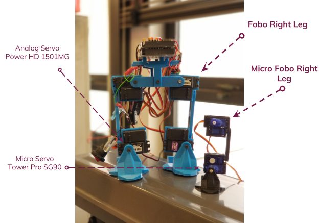
Goal for this project is to design and manufacture a BiPed Robot. This robot will be slightly similar to the BiPed robot that was created in Spring 2016 and another bipedal robot named FOBO, created by Jonathan Dowdall. Our design will be based on FOBO but will be much smaller in size that implements micro servos for walking and turning. For sensing its surroundings, the robot will utilize ultrasonic and Infrared sensors. Other key differences between the FOBO and our micro version of FOBO are that:
- The head of our robot shall house a 3DoT board, servos controller shield, and a sensor shield.
- The movement of our robot will be conducted via SG90 micro servos that will replace the clunky and oversized Hitec HS-805BB servos.
- The legs of our robot will have a more efficient method to mount and utilize its servos for weight reduction and for longer walking steps.
- Our robot will utilize Bluetooth technology for user to robot communication and movement control
- The robot’s power system will be changed from heavy LIPO batteries to a single Samsung 18650 battery located near the robot’s center of mass.
The mission of Project BiPed is to design the BiPed to navigate a predesigned maze. The BiPed shall be able to navigate the maze with user input from the Arxterra App/Control Panel. The BiPed will be able to memorize the user-defined path and will be able to navigate it autonomously. In addition, the BiPed will acknowledge other robots while traversing the maze and avoid collisions using its sensors. To learn more about the mission objective you can take a look here. For preliminary maze designs and definitions take a look here.
Project: Level 1 Requirements
By: Jeffery De La Cruz (MST Engineer)
Verified By: Miguel Gonzalez (Project Manager)
Will:
L1-1: Micro FOBO will stand on its own without any physical help.
L1-2: Micro FOBO’s electronic components will be easily assembled and disassembled.
L1-3: Micro FOBO will have 2 legs.
L1-4: Micro FOBO will be a toy robot based on the design of the FOBO by Jonathan Dowdall.
L1-6: Micro FOBO will fit within the classroom cabinets shelves. 28”x13”x14.5”
L1-7: Micro FOBO will utilize a 3DoT board or Sparkfun Pro Micro 3.3V/8MHz.
L1-8: Micro FOBO’s part components will be 3D printed using the material carbon fiber PLA.
L1-9: Micro FOBO will not exceed a print time of 7.80 hours. Upon approval of the waiver.
Shall:
L1-10: Micro FOBO shall not exceed a cost of $250 to construct.
L1-11: Micro FOBO shall be 60% or less of the overall size of Jonathan Dowdall’s FOBO
L1-12: Micro FOBO shall detect intersections in the maze.
L1-13: Micro FOBO shall be able to perform static walking.
L1-14: Micro FOBO shall produce 90 degrees turn.
L1-15: Micro FOBO shall be guided through the maze with the use of the Arxterra application.
L1-16: Micro FOBO shall record the path of the maze.
L1-17: The Micro FOBO shall traverse the maze using the recorded path.
L1-18: Micro FOBO shall be able to traverse cloth, paper, and linoleum materials.
L1-19: The Final Biped shall be completed by May 10th, 2018.
Should:
L1-20: Micro FOBO should step over a square rod 1cm tall, 1 cm wide by 10 cm long
L1-21: Micro FOBO should be able to perform dynamic walking
System/Subsystem: Level 2 Requirements
By: Jeffery De La Cruz (MST Engineer)
Verified By: Miguel Gonzalez (Project Manager)
Will:
L2-1: Micro FOBO will be connected via Bluetooth to the app on an android phone.
L2-2: Micro FOBO dimensions of the robot will need to be small enough to fit in a 4in by 4in box for maze purposes.
L2-3: Micro FOBO will use SG90 micro servos.
Shall:
L2-4: Micro FOBO shall use UV/IR sensors to detect intersections.
L2-5: Micro FOBO shall use the color of the maze to establish if it needs to turn. black (0,0,0) green (0,255,0) for line following.
L2-6: Micro FOBO shall use a battery that outputs 3.7V nominal.
L2-7: The user shall use the Arxterra application to move the robot forward, backward, left, and right.
L2-8: Micro FOBO connectors shall be able to connect and reconnect all the wiring in less than 10 min.
L2-9: Micro FOBO wiring shall be nice and clean with the use of terminal blocks, contact pins, 2.0mm PH series JST connectors, and barrel connectors.
L2-10: Micro FOBO shall play a musical tune when the maze is completed.
L2-11: Micro FOBO shall have indicating LEDs to demonstrate either a left or right turn.
L2-12: The Micro FOBO shall record the path of the robot on the 3DoT board or the Sparkfun Pro Micro 3.3V/8MHz to navigate the robot through the maze.
L2-13: Micro FOBO shall use a 3D printed chassis and leg components.
L2-14: Micro FOBO shall measure within 4.5” x 3.25” x 7.25”.
L2-15: Micro FOBO shall weigh no more than the allocated mass of 460g.
L2-16: Micro FOBO shall detect objects 8 inches from it.
Should:
L2-17: Micro FOBO should be able to see other robots to avoid a collision. The robot will stop completely and wait for clearance. (Ultrasonic sensor)
L2-18: Micro FOBO should take a bow at the end of the maze as a victory celebration.
System Block Diagram
By: Jorge Hernandez (E&C Engineer)
Verified By: Miguel Gonzalez (Project Manager)
After looking at all the constraints and requirements for the robot our group came up with a system block diagram that could help us visualize how the robot’s components interacted with one another. This diagram made it clear to understand where initial designs should be made and provided great insists on some challenges we would have in the future. Below we link the blog post to the system block diagram the group made.
Work Breakdown Structure
By: Miguel Gonzalez (Project Manager & Manufacture)
When working on a team project it’s important to break down the project into general tasks and assign them to team members. Typically a chart is created to easily visualize how the work is divided among team members, this called a WBS (Work Breakdown Structure). Here we link to our post demonstrating and explaining our WBS.
Product Breakdown Structure
By: Jeffery De La Cruz (MST Engineer)
Verified By: Miguel Gonzalez (Project Manager)
Based on System Block
Sensor Suite
- The color sensor will be able to detect colors and its data input range Ex, black (0,0,0) green (0,255,0) for line following.
- Will be able to see intersection sign on the maze and differentiate its color from the path lines.
- Shall be able to see other robots to avoid a collision. The robot will stop completely and wait for a command. (Ultrasonic sensor/IR)
- The robot should have to indicate LEDs to show where the robot plans to make a turn (left or right)
Smartphone App
- Will allow usage of the app to navigate the robot through the maze through forward, back, left, and right commands.
- Will record the path of the robot in 3Dot board to navigate robot without the user controlling it.
- The robot will be connected via Bluetooth to the app on an android phone.
Chassis
- The wiring for the robot shall be nice and clean with the use of terminal blocks, contact pins, 2.0mm PH series JST connectors, and barrel connectors.
- All connectors shall be able to connect and reconnect all the wiring in less than 5 min.
- Dimensions of the robot will need to be small enough to fit in a 6in by 6in box for maze purposes.
Battery
- The robot power management system will use two 1000mAh 2S 20C Lipo Pack rechargeable LIPO batteries.
Interface Matrix
By: Jeffery De La Cruz (MST Engineer)
Verified By: Miguel Gonzalez (Project Manager)
After verifying the product breakdown structure we began listing the interfaces for the 3DoT Board that were going to connect to our sensors and motors.
Prototype Fritzing Diagram for Biped
By: Jorge Hernandez (E&C Engineer)
Verified By: Miguel Gonzalez (Project Manager)
With the product breakdown structure and the interface matrix completed we began the prototyping the circuit and making connections to the servos and sensors. The Fritzing application allows a physical breadboard design to be created digitally. By designing a digital version, and verifying its functionality we can have a smooth transition to creating the PCB.
Mechanical Drawings
By: Miguel Gonzalez (Project Manager & Manufacture)
This blog demonstrates the process of developing all the parts for the Micro Fobo and the unique ways we solved issues throughout the building process.
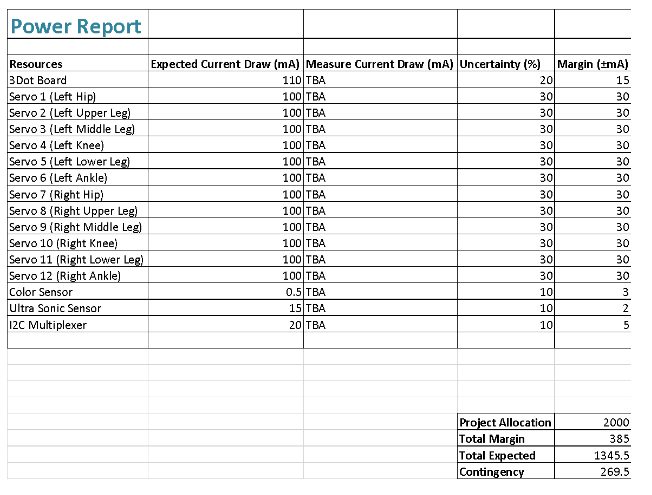
Resource Reports (Power, Mass, Cost)
By: Jeffery De La Cruz (MST Engineer) and Miguel Gonzalez (Project Manager and Manufacturing )
Summary of Experiments / Rapid Prototyping Completed and Software Tests
By: Miguel Gonzalez (Project Manager & Manufacture)
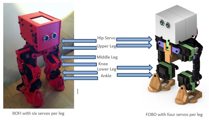
It has been approximately eight weeks since the start of the semester and most of the first month consisted of mainly research and write-ups. But after the first month, we began experimenting with small components and sections of our BiPed. We started by looking at the legs of our robot as we knew that making the robot walk on two legs was a crucial part of our design. We created a copy of the 2016 Fall ROFI design and just focused on the legs of that robot. This initial design consisted of having 6 servo motors operating the leg and foot. Using the blog post on that robot and using help from projectbiped.com we were quick to get the robot’s leg to move. If you would like to see images and videos of the robot when it’s operating, you can view our drive folder here. In this configuration, the robot’s leg is very robust and can do very intricate movements while maintaining the robots balance. The issue with this design is that nearly 70 percent of all the weight of the robot consists of the legs alone. We knew that if we can decrease the weight on the robot we could have easier walking movements that in theory can speed up its walking speed. Our secondary design for the robot was to reduce the number of servos operating on the legs by only having four servo motors instead of six.
This newer design would remove both the knee servo and middle leg servo on both legs. Theoretically, the newer design should remain functional and provide the ability to take longer strides when walking. It is important to note that the designs for the new leg designs have been modeled and 3D printed but the test will take place on March 17, 2018. This experiment will allow us to verify that the legs can perform walking movement and maintain a higher walking speed than the six-servo design.
Concluding Thoughts
Resources
Project Video: YouTube
PDR: EE400D Design Presentations
Project Libre Excel: Burndown
Verification and Validation Documents: https://www.arxterra.com/spring-2018-project-biped-verification-and-validation-pass-fail-matrix/
Solidworks Files: Micro FOBO
Fritzing Files: Fritzing-20180331T202552Z-001
EagleCAD files (zip folder): Copy of EagleLibraries | 400-D gerber-20180518T192139Z-001 | ServoShield2Eagle-20180518T192149Z-001
Arduino and/or C++ Code: Walking and Turning | Remote_Control FOBO
Bill of Materials: https://www.arxterra.com/spring-2018-biped-preliminary-budget/ Budget Table pdf
3D print Time: https://www.arxterra.com/spring-2018-biped-3d-print-time/
List of all our blog post: https://www.arxterra.com/news-and-events/members/3dot-robots/biped-generations/biped-generation-5/
Spring 2018: Biped Software Diagrams
/in Biped Generation #5/by Miguel GonzalezBy: Miguel Gonzalez (Project Manager & Manufacturing)
Approved By: Miguel Garcia (Quality Assurance)
One of the most helpful things to do before you start writing code is to create a flowchart and a software block diagram. These diagrams will help you understand the overall construction and function of the code. In this blog post, we will be looking at the diagrams our team created to visualize how the Micro FOBO should function. These charts introduce tasks the software must complete reaching mission success.
Related requirements:
Level 1
L1-12: Micro FOBO shall detect intersections in the maze.
L1-13: Micro FOBO shall be able to perform static walking.
L1-14: Micro FOBO shall to produce 90 degree turn.
L1-15: Micro FOBO shall guide the Micro FOBO through the maze with the use of the Arxterra application.
L1-17: The Micro FOBO shall traverse the maze using the recorded path.
Level 2
L2-5: Micro FOBO shall use the color of the maze to establish if it needs to turn.
L2-10: Micro FOBO shall play a musical tune when the maze is completed.
L2-11: Micro FOBO shall have indicating LEDs to demonstrate either a left or right turn.
L2-16: Micro FOBO shall detect objects 8 inches from it.
L2-17: Micro FOBO should be able to see other robots to avoid collision. Robot will stop completely and
wait for command. (Ultrasonic sensor)
L2-18: Micro FOBO should take a bow at the end of the maze.
Software Block Diagram
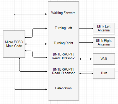
The software block diagram can be thought of as individual code modules that work together to create the overall software system for the Micro FOBO.
As you can see in figure 1 the left block represents the “main code” section. In this section, you will find all the functions and call to functions the robot utilizes for the completion of tasks. This section houses the main code that runs in a loop calling on subroutines to make readings or to simply perform a task. The middle section of the block diagram represents all the available “functions/subroutines” the robot has available. Some functions include Walking forward, turning, and taking measurements. It is clearly visualized from the arrow movement that the main code of FOBO has the ability to call subroutines and functions located in the middle section of figure 1. Finally, looking at the right part of the chart we can see the “actions” section which is the code that runs after certain functions are run. For example, if Turning Left is run then the action of blinking the left LED antenna will be performed.
Software Flow Chart
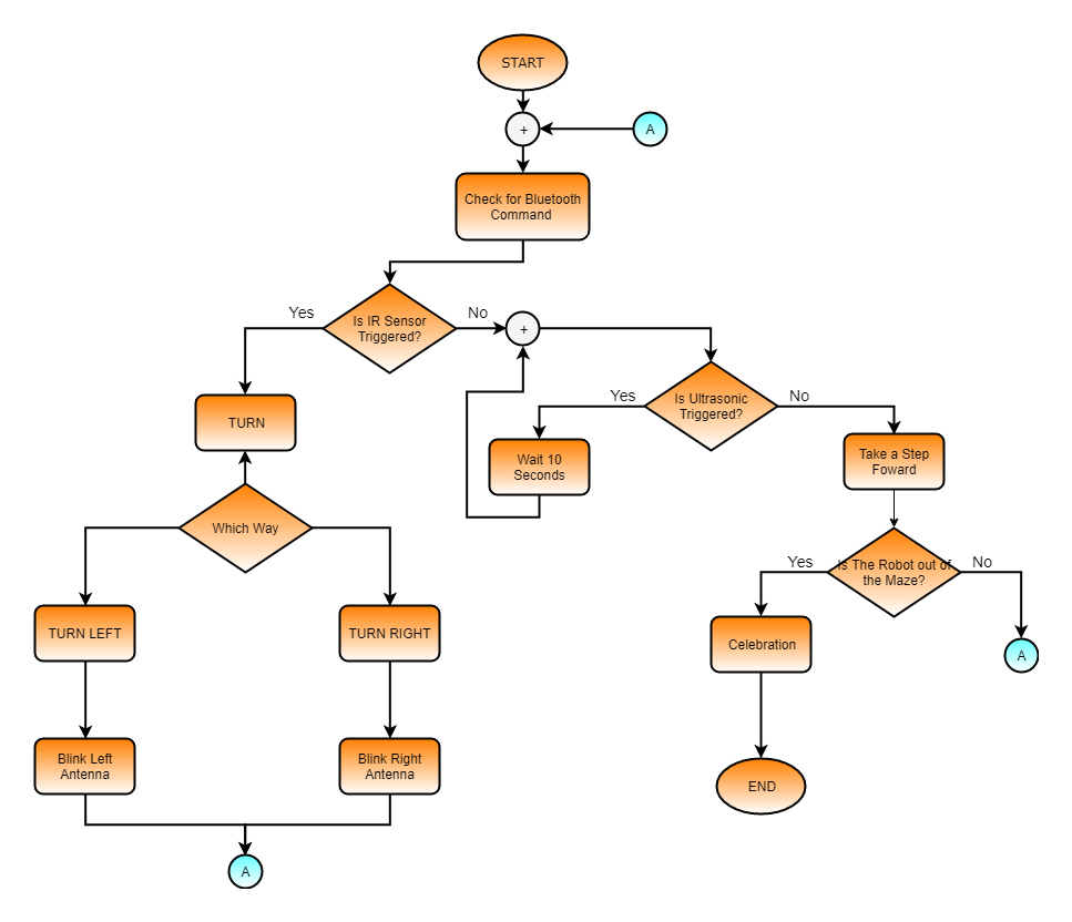
Although the software block diagram is a useful tool for understanding the subroutines and actions of the robot it can still be difficult to use as a template for writing code. For this reason, we make software flow charts. We can use the block diagram above to make the flowchart that you see below.
As you can see, this flowchart is a visualization of how the code runs showing all it’s decision procedures and actions it takes whether its tests are true or false. Instead of reading the chart from left to right like the previous diagram we read this chart from top to bottom. As we can see the first thing the code will do when starting up is check for a Bluetooth command if not command is present it will proceed to check if the IR sensor is triggered. A yes answer will cause the code to run the “turn” function which causes the program to ask “which direction.” Once instructions are received the program will perform the next action and blink the corresponding LED. If the IR sensor is not triggered then it will check the ultrasonic sensor. If triggered, Micro FOBO will assume there is a robot crossing in front of it so it is instructed to wait until it’s cleared. The program will loop back every 10 seconds to check if the path has been cleared. Once cleared the program will proceed to take a step forward. At every step, the robot will ask itself if it has cleared the maze. If the answer is false then the program loops back up to the beginning. It is quite apparent that by using these two diagrams we can fully understand the behavior of the robot and how its code should be written to produce the desired functions. In the next few weeks, our E&C engineer will be utilizing these diagrams to write the code necessary to have Micro FOBO navigate through the maze and achieve all customer requirements.
References
Spring 2018: Biped Action Code
/in Biped Generation #5/by Miguel GonzalezBy: Jorge Henandez (Electronics & Control)
Verified By: Miguel Gonzalez (Project Manager)
Approved By: Miguel Garcia (Quality Assurance)
At first we were given the task to complete a previous ROFI biped. Not knowing how many of the integration systems worked, research was required. Most of the wires were cut from ROFI so this process took around 1 and a half to 2 weeks to even get ROFI functional. Once an Arduino Mega and the shield provided from last semester were connected properly, along with the external power source, it was finally time to have ROFI moving.
Robot POSER, which is a beta robot poser provided from projectbiped.com, allows new action sequences and servo calibrations to be created for ROFI/ FOBO. The application controls the robot via a USB cable from the Arduino Mega (Uno for FOBO) to a laptop or desktop computer. The folder containing the application also has 3 actions (walk, static walk, and turn right) so you can get the robot moving once it is calibrated. To see us calibrate ROFI click here ROFI Calibration .
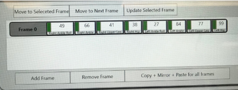
Similar steps were taken to get FOBO walking and used a FOBO servo centering program, provided from projectbiped.com, along with the FOBO poser to get our calibrations for each servo. Having our own unique calibrations, we saved a frame action which allowed us to bring Micro FOBO back to its center servos which are listed below.
Walking Action:
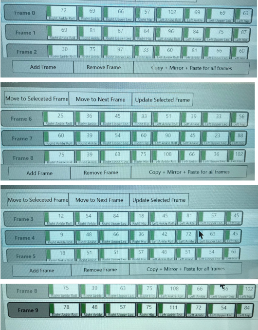
The walking action looks like the following, which moved the servos in a walking motion for a continuous loop until asked by the user to stop.
Another action was loaded onto FOBO Poser to make the biped mimic walking. Below is the sequence of the frames as it controlled the servos in 10 frames to adjust it walking while maintaining its balance.
References
Spring 2018: BiPed PCB Assembly
/in Biped Generation #5/by Miguel GonzalezBy: Jorge Hernandez (Electronics & Control)
Verified By: Miguel Gonzalez (Project Manager)
Approved By: Miguel Garcia (Quality Assurance)
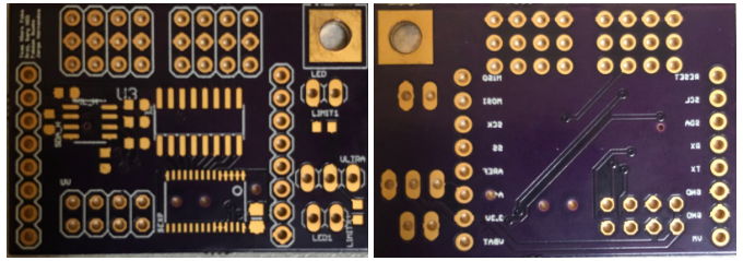
The E&C Engineer, once I constructed Micro FOBO’s PCB, which consisted of a servo PWM expander and 2-channel multiplexer components, the team, and I realized we used the wrong PWM driver. The PCB from Oshpark came out perfectly other than an error which prohibited us to use it which was a shame since we were out of time to order a new PCB. For specifics, our PCB was a 1.58 x 1.10 inch (40.2 x 27.9 mm) 2 layer board.
For the PCB assembly, it was not possible as the parts from DigiKey were the wrong parts or else I would have started the assembly process. The wrong Digikey parts and images that came in can be found here (BOM blog post). For future Biped teams, specifically FOBO, as the E&C who spent all semester learning EagleCad, I suggest using the CD-4017 decoder chip as that is the chip FOBO is supposed to run on according to projectbiped.com. Gerber files of my PCB can be found here (Eagle Cad files) if needed.
References
Spring 2018: Biped FOBO Existing obstacle avoidance software test
/in Biped Generation #5/by Miguel GonzalezWritten By: Jorge Hernandez (Electronics & Control)
Verified By: Miguel Gonzalez (Project Manager)
Approved By: Miguel Garcia (Quality Assurance)
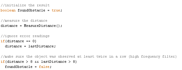
In order to avoid obstacles, we implemented the SEN136B5B sensor ultrasonic code within the given navigation program from projectbiped.com. I also did my own code which turned on an LED to detect when the ultrasonic detected 8cm or less. This was made because Micro Fobo already had navigation code which used Ultrasonic to turn Right when it detected 5 cm and I did not want to take credit for code that was not mine. Within the provided code, the only changes we had to make is to have the function found Obstacle read the value of 8 cm. If Micro FOBO’s ultrasonic read anything above 8 cms, it would provide a zero, or a false to the function found Obstacle. Below is the given code with the minor changes in order for Robot avoidance.
Below is a video of the testing performed which would essentially have Micro FOBO walk and when detecting an obstacle at 8cm’s, instead of the LED going on, it would stop Micro FOBO completely.
https://drive.google.com/open?id=1ppkFJqBtTFxKPoDTRbCh50Uc4DUi5A1O
Initially, we wanted to have the LEDs that were on top of Micro FOBO’s head turn on when it detected 8cm but in our dem,o there was a loose wire which caused miscommunication and could not make FOBO move at all. Below is a video on how we would have used the idea of Robot avoidance with the Arduino code provided as well.
// Jorge Hernandez
//Ultrasonic Sensor HC-SR04 and Arduino Tutorial
//Dejan Nedelkovsk
// defines pins numbers
const int trigPin = 9;
const int echoPin = 10;
const int ledPin=13;
// defines variables
long duration;
int distance;
void setup() {
pinMode(trigPin, OUTPUT); // Sets the trigPin as an Output
pinMode(echoPin, INPUT); // Sets the echoPin as an Input
Serial.begin(9600); // Starts the serial communication
}
void loop() {
// Clears the trigPin
digitalWrite(trigPin, LOW);
delayMicroseconds(2);
// Sets the trigPin on HIGH state for 10 micro seconds
digitalWrite(trigPin, HIGH);
delayMicroseconds(10);
digitalWrite(trigPin, LOW);
// Reads the echoPin, returns the sound wave travel time in microseconds
duration = pulseIn(echoPin, HIGH);
// Calculating the distance
distance= duration*0.034/2;
if (distance <9){  // if less than 9 cm's then the LED will turn on
  digitalWrite(ledPin,HIGH);
}
else{
  digitalWrite(ledPin,LOW); // if not, LED will stay on
}
// Prints the distance on the Serial Monitor
Serial.print("Distance: ");
Serial.println(distance);
}
References
Spring 2018: Biped Breadboard Build and Test
/in Biped Generation #5/by Miguel GonzalezWritten By: Jorge Hernandez (Electronics & Control)
Verified By: Miguel Gonzalez (Project Manager)
Approved By: Miguel Garcia (Quality Assurance)
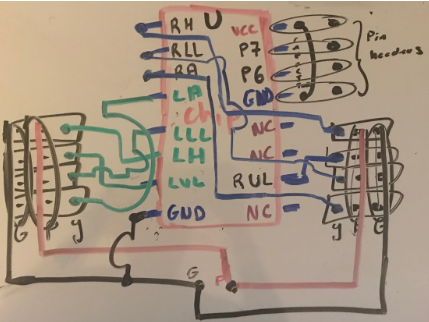
Our design ended up being breadboarded which fit inside of Micro FOBO’s head. The reason we had to resort to breadboarding is due to the fact of using a wrong chip. Originally Fobo operated on the CD-4017 decoder chip as we used the PCA9685 16-channel PWM driver on our PCB. Due to this error, in order to move Micro Fobo we need to use the 4017 decoder and with limited time, we breadboarded and tested. In order to build and use the 4017 decoder to drive the 8 micro servos Micro Fobo uses, I drew up a schematic and pinouts to simplify which derive from projectbiped.com.
To clarify figure 1
- RH= PWM connection to Right HIP
- RLL= PWM connection to Right Lower Leg
- RA= PWM connection to Right Ankle
- RUL= PWM connection to Left Upper Leg
- LH= PWM connection to Left HIP
- LLL= PWM connection to Left Lower Leg
- LA= PWM connection to Left Ankle
- LUL= PWM connection to Left Upper Leg
- NC= no connection
- GND= ground connection
- VCC= connection to 5 v
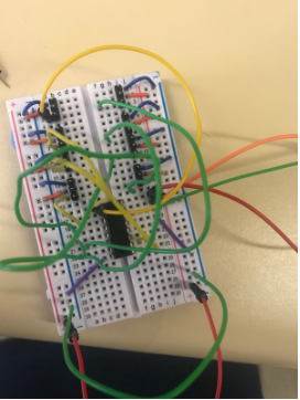
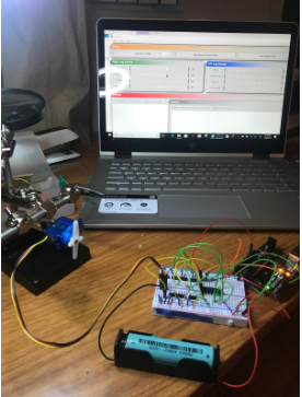
In figure 2 one can see the actual completed breadboard.
Using this breadboard shield gave us full control of each individual servo when connecting a 4.7 V battery to it. The program used to calibrate was provided by Projectbiped.com which was called FOBO poser. The breadboard build and test were successful when testing individual micro servos. The walking test will be a more challenging task as it uses all 8 micro servos simultaneously.
Below is a video of the actual calibration.
References
Spring 2018: BiPed Custom PCB Layout/Design & Modify Micro FOBO for 3DoT
/in Biped Generation #5/by Miguel GonzalezBy: Jorge Hernandez (Electronics & Control Engineer)
Verified By: Miguel Gonzalez (Project Manager)
Approved By: Miguel Garcia (Quality Assurance)
Table of Contents
Introduction
The PCB layout for Micro FOBO was modified to fit the 3DoT which will be provided by Professor Gary Hill. The way we modify Micro FOBO for a 3DoT board is by having the blank 3DoT layout template, which was kindly provided to us, and implement the pinouts in our board layout design. Once we have our template where the pins are ready to mount to the 3 DoT directly, we can start routing and building the PCB for Micro FOBO.
Given
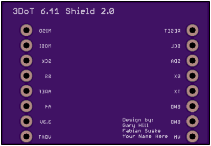
This is the blank pin headers for the 3DoT which was created by Gary Hill and Fabian Suske for the Spring 2018 semester.
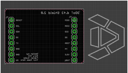
Board layout for 3 DoT pin header above with the correct dimensions, will be used as a foundation to build the PCB for Micro FOBO. This board layout was also provided by Gary Hill and Fabian Suske.
Non approved layouts
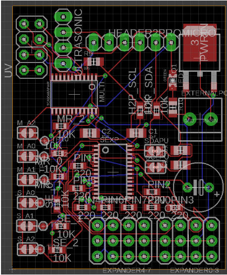
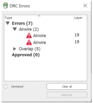
When I first started routing, it was a total mess to be honest. I had all the addresses for the servo expander & Multiplexer on the board layout which just took up a lot of space. I was also using the wrong Multiplexer as it was an 8 Channel Multiplexer which was just a huge waste of space as I only needed a 2-channel multiplexer. Another mistake I had was having everything connected to my external battery source ‘VBATT’ which is not necessary because everything but the Servo Expander operates at 3.3V just like the 3DoT. As one can see I was using the 4 pin header for the Ultrasonic(HC-SR04) which only operates at 5 V. Now using a SEEED ultrasonic, which operates at 3.3V and only has 3 pins, eliminates a need for a booster shield. I also learned about DRC, which is “Design rule checking or check(s) (DRC). This is the area of electronic design automation that determines whether the physical layout of a particular chip layout satisfies a series of recommended parameters called “design rules” and my first board layout had many errors as seen below.
Second draft
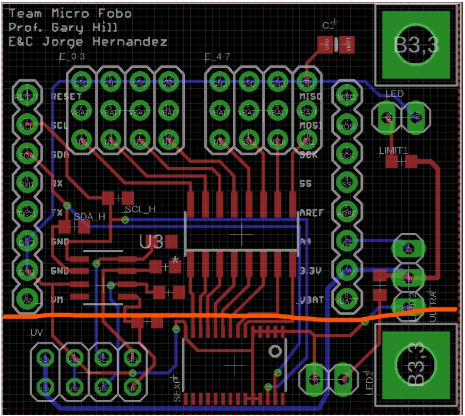
Having 90-degree bends are not allowed and is a reason this board layout did not get approved. Another reason is how some wires were not routed to its simplest form, therefore the routing needed to be more direct. Since the plan was to mount our PCB on top of the 3DoT, everything below the orange line will interfere with the battery which will need to be moved to accommodate this issue. Also, the size of this vias needs to be increased as they are too tiny. The power routing width needs to be increased to satisfy the current running through the power routings.
Final approved Layout
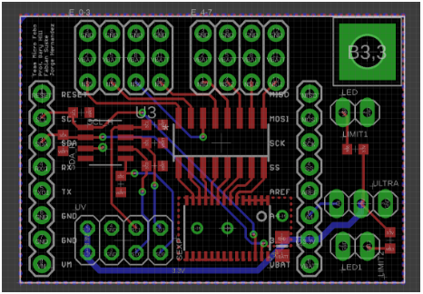
The reason this board is approved
- No 90-degree routes
- Direct/clean wiring
- Larger vias
- No battery interference
- Power wiring widths are larger
- Ratsnest and DRC were satisfied
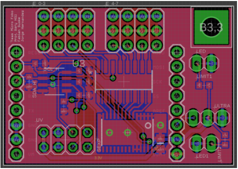
Finished routed board
Custom Parts
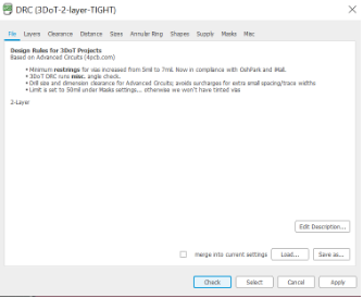
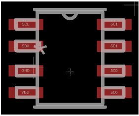
The PCA9540BDPN 2-channel multiplexer default part from Digikey gave us overlapping pinouts which didn’t go through OSHParks DRC. Therefore I had to go directly to its library and move the pins apart in order to use this part.
Before the modified PCA9540BDPN chip
It is obvious changes needed to be done to prevent overlapping
After the modified PCA9540BDPN chip
Modified pins and DRC approved.
Conclusion
My Micro FOBO board layout consists of 2 UV headers, a Servo Expander, 8 micro servo pin headers, a coupling capacitor, resistors, LED pin headers, ultrasonic pin headers, and a 2 channel multiplexer. The exact specifications of these components can be found at Micro FOBO Electronics Component BOM blog post. The final PCB board layout is 39.958 x 27.941 mm which fits perfectly on top of the 3 DoT which is 60×74 mm which overall fits within Micro FOBO’s head which measures 60×74 mm.
References
- https://www.arxterra.com/spring-2016-rofi-pcb-layout/
- https://en.wikipedia.org/wiki/Design_rule_checking
Spring 2018: BiPed (Micro FOBO) System Block Diagram
/in Biped Generation #5/by Miguel GonzalezBy: Jorge Hernandez (Electronics & Control Engineer)
Verified By: Miguel Gonzalez (Project Manager)
Approved By: Miguel Garcia (Quality Assurance)
System Block Diagram
New and improved System Block Diagram for Micro Fobo, which shows in a general diagram, how many pins will be needed for each component and how they connect to each other. As seen, we are using a total of 5 sensors, a custom PCB, Bluetooth module, external battery and of course a Pro Micro. This helps a lot for our E&C engineer when it comes to PCB designing as they need to plan accordingly.
The sensors subsystem (custom PCB) will be in charge of telling Micro FOBO’s next action. When the IR sensor on the UV breakout board sense a change in IR reading, this will alert the Pro Micro which ultimately leads to the Actuators subsystem (Micro Servos) to adapt accordingly based on our code. The same process will occur when the Ultrasonic sensor senses an object or a wall ahead of Micro Fobo. Bluetooth is considered a sensor because it collects inputs from a source, in this case, an Android phone then sends that data to the Pro Micro thus telling Micro FOBO what to do based on our code. The communication subsystem (Bluetooth module) is connected to the Pro Micro because through Bluetooth the Arduino will obtain information on the action it will take. The Power subsystem consists of the battery which has been tested for our overall system and a regulator to ensure the safety of the system and the user(s). Our Actuator subsystem is our output, Micro FOBO’s desired movement, based on our sensors and code

