Written by Zachary de Bruyn
Troubleshooting Results
During the integration of the peripheral devices it was discovered that the GM6 Motors did not operate accordingly. When the motors were inserted into the JP2 and JP3 ports of the 3DoT board, the motors would not operate with the provided code designed to test the GM6 Motors.
/*
Sample Code to run the Sparkfun TB6612FNG 1A Dual Motor Driver using Arduino UNO R3

This code conducts a few simple manoeuvres to illustrate the functions:
  - motorDrive(motorNumber, motorDirection, motorSpeed)
  - motorBrake(motorNumber)
  - motorStop(motorNumber)
  - motorsStandby

Connections:
- Pin 3 ---> PWMA
- Pin 8 ---> AIN2
- Pin 9 ---> AIN1
- Pin 10 ---> STBY
- Pin 11 ---> BIN1
- Pin 12 ---> BIN2
- Pin 5 ---> PWMB

- Motor 1: A01 and A02
- Motor 2: B01 and B02

*/
// FOR V5.03
//Define the Pins

//Motor 1
int pinAIN1 = 12; //Direction
int pinAIN2 = 4; //Direction
int pinPWMA = 6; //Speed

//Motor 2
int pinBIN1 = 9; //Direction
int pinBIN2 = 5; //Direction
int pinPWMB = 10; //Speed

//Standby
int pinSTBY = 8;

//Constants to help remember the parameters
static boolean turnCW = 0;  //for motorDrive function
static boolean turnCCW = 1; //for motorDrive function
static boolean motor1 = 0;  //for motorDrive, motorStop, motorBrake functions
static boolean motor2 = 1;  //for motorDrive, motorStop, motorBrake functions

void setup()
{
  Serial.begin(9600);
  //Set the PIN Modes
  pinMode(pinPWMA, OUTPUT);
  pinMode(pinAIN1, OUTPUT);
  pinMode(pinAIN2, OUTPUT);

  pinMode(pinPWMB, OUTPUT);
  pinMode(pinBIN1, OUTPUT);
  pinMode(pinBIN2, OUTPUT);

  pinMode(pinSTBY, OUTPUT);
  asm("in r24, 0x35");
  asm("ori r24, 0x80");
  asm("out 0x35, r24");
  asm("out 0x35, r24");
}

void loop()
{
  //Assuming that the input command from the arxterra app can be read as an integer

 motorDrive(motor1, turnCW, 255);

//  delay(500);
//  motorBrake(motor1);
//
//  delay(500);
  //Command to make spider walk backward

  motorDrive(motor2, turnCCW, 255);
//  delay(500);
//  motorBrake(motor2);
//  delay(500);
}

void motorDrive(boolean motorNumber, boolean motorDirection, int motorSpeed)
{
  /*
  This Drives a specified motor, in a specific direction, at a specified speed:
    - motorNumber: motor1 or motor2 ---> Motor 1 or Motor 2
    - motorDirection: turnCW or turnCCW ---> clockwise or counter-clockwise
    - motorSpeed: 0 to 255 ---> 0 = stop / 255 = fast
  */

  boolean pinIn1;  //Relates to AIN1 or BIN1 (depending on the motor number specified)


  //Specify the Direction to turn the motor
  //Clockwise: AIN1/BIN1 = HIGH and AIN2/BIN2 = LOW
  //Counter-Clockwise: AIN1/BIN1 = LOW and AIN2/BIN2 = HIGH
  if (motorDirection == turnCW)
    pinIn1 = HIGH;
  else
    pinIn1 = LOW;

  //Select the motor to turn, and set the direction and the speed
  if (motorNumber == motor1)
  {
    digitalWrite(pinAIN1, pinIn1);
    digitalWrite(pinAIN2, !pinIn1);  //This is the opposite of the AIN1
    analogWrite(pinPWMA, motorSpeed);
  }
  else
  {
    digitalWrite(pinBIN1, pinIn1);
    digitalWrite(pinBIN2, !pinIn1);  //This is the opposite of the BIN1
    analogWrite(pinPWMB, motorSpeed);
  }

  //Finally , make sure STBY is disabled - pull it HIGH
  digitalWrite(pinSTBY, HIGH);

}

void motorBrake(boolean motorNumber)
{
  /*
  This "Short Brake"s the specified motor, by setting speed to zero
  */

  if (motorNumber == motor1)
    analogWrite(pinPWMA, 0);
  else
    analogWrite(pinPWMB, 0);
}

void motorStop(boolean motorNumber)
{
  /*
  This stops the specified motor by setting both IN pins to LOW
  */

  if (motorNumber == motor1) {
    digitalWrite(pinAIN1, LOW);
    digitalWrite(pinAIN2, LOW);
  }
  else
  {
    digitalWrite(pinBIN1, LOW);
    digitalWrite(pinBIN2, LOW);
  }
}

void motorsStandby()
{
  /*
  This puts the motors into Standby Mode
  */
  digitalWrite(pinSTBY, LOW);
}
With no consideration for the other peripheral devices, and just the GM6 motors attached to the board, the motors are programmed to operate at the HIGH setting as depicted in the code (255). Instead the motors would only “tick”. The following configurations were utilized to try and troubleshoot the issue with the GM6 Motors.

The above test results above suggest that the board is not providing the necessary voltages to the motors while both are plugged into the board. I referred to the schematic and started by investigating the voltages being read to the motor driver pins A01 and A02

While operating at nominal conditions, I find that the voltages read from these pins are similar to what I was measuring on the motors. I had similar results when performing the measurements for JP3 under identical conditions. Once both motors were connected, however, those voltages dropped down to 4.2 to 7.2 mV.
Testing the TPS61200
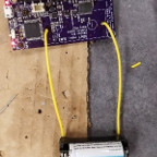
The traces of the motor driver were followed back to the TPS61200 buck/boost converter, suspecting that it might be the culprit. However in order to get to the TPS61200, as well as the other IC’s, the CR123 battery holder needed to be replaced and rigged in such a manner that it would still operate the 3DoT board.
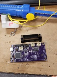
As shown in the figure, the battery holder was removed by removing the solder from the holder leads on the back side of the 3DoT board. Once the battery holder was removed stripped wire was soldered to the battery holder and then soldered onto the 3DoT board. This setup, while ugly, is only temporary; and what has been done can be undone and the battery holder can be reapplied in the correct way once the troubleshooting of the board has completed.
Once the battery holder jumper wires were soldered onto the board, the 3DoT was operationally checked first by simply powering on the board, and then by verifying the board was still programmable.
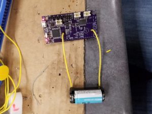
By reviewing both the data sheet of the TPS61200 and the schematic of the v5.03 board, the power pins of the TPS61200 were measured as well as their corresponding input pins to the dual motor driver.
The first pin measured was the EN pin of the TPS61200 which is directly linked to the power switch of the battery. Measuring the EN pin resulted in 4.18 V. By verifying the fact that the EN pin was reading the same voltage as the battery we could safely assume that the network from the battery holder to the input of the TPS61200 was operating correctly, including the 1.5A fuse which lies between the battery holder and the switch. The output pin VOUT was then measured to assure that it was providing the 5 V necessary to power the dual motor driver. Upon inspection, we find that the VOUT pin indeed does measure 5 V (5.06 V to be exact). This node was then traced back to the motor driver.
While operating under no load (ie no motors connected to the motor driver) the voltages were measured at pins VM1, VM2, and VM3 of the dual motor driver. The voltages measured at the motor driver were approximately 5 V for all three of the inputs to the driver. The SAME voltages were read at the three inputs when both motors loads were attached to the board.
By referring to the previous test of the dual motor driver, it is recalled that while a motor was operating at optimal conditions the output nodes of the motor drivers (AO1, AO2, BO1, BO2) were 5 V, however once another motor load was placed onto the motor driver, the voltages across the nodes would read 4 to 7 mV.
Reviewing the datasheet of the motor driver we see the following block diagram, and the blocks H-SWA and H-SWB.

These H-SW blocks correspond with the MOSFET current mirror images shown below.

By analyzing the diagram, it is my belief that the cause of the motor stall issue is that there is a blown MOSFET somewhere in the H-SW block that causes perhaps a short which causes the motors both to be pulled to ground while simultaneously plugged in to the 3DoT board. The voltage parameters are nominal leading up to the motor driver.
