By: Daniel Guerrero (M&D Engineer)
Verified By: Ernie Trujillo (Project Manager)
Approved By: Miguel Garcia (Quality Assurance)
1st Iteration: February 16th, 2018
Introduction:
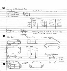
This is the beginning of creating a scale model of the German 302 goliath tank. Since it is the beginning of the semester and my team wasn’t set on the location of all of our electrical components inside the tank I wanted to create an open design to be able to fit any of the pieces they needed.
Details:
For this design I wanted to follow our professor’s request in having both motors in the back/front of the tank. For that reason I created the platform, but at the same time I didn’t want it to take up the entire back part of center console so I left a gap underneath for wires and other pieces that might need to go underneath. The opening at the bottom of the center console was to allow the line following sensors to function internally. As for the top and side pieces I wanted to keep them open to have options in terms of our placement of all of our components. Lastly, the side pieces were made thick enough to be able to screw into and attach to the bottom part of the tank. The design is meant to be simple yet sturdy to accommodate for the weight of the components being put into the tank.

Figure 1. Shows an explosive view of the first design I made to focus more on the overall shape of the tank and start sizing components that we could be using.
Conclusion:
It is better to have contacted all of your printing resources beforehand, for some reason this print took a while to get to me and I had to move on to the next design the next day. Overall, this design is much larger than what we want to get to, but it would serve as a good foundation and a start to what we have coming.
2nd Iteration: March 2nd, 2018
Introduction:
Following the German 302 goliath tank I leaned towards the previous model for my inspiration. At the same time I also wanted focus my efforts on designing an efficient and realistic side piece, for that reason I wanted to test different methods for the design.
Details:
With this design I decided to try and get close to the older model from a previous year. In this design I wanted to skip forward in creating a housing space for the motors and making a permanent space for them. On the same piece I also introduced the opening on the front of the bottom piece for the range finder.
I also started to design the Hinges for the side portion. I wanted to deviate from the old model and crate a moving support hinge so my first thought was to create half of the hinge beginning from the bottom of the side pieces. And the small circular parts in between the hinges are meant for the other end of the spring to connect to from the “bottom wheel hinge” photo.
As for the top portion I wanted to keep the inside accessible while mimicking the lids in the original German goliath 302 model. I wasn’t sure how much room they needed inside the tank so I kept it open in case of overflow.
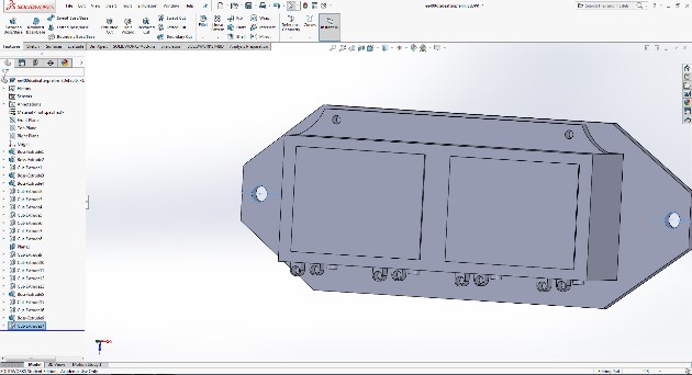
Figure 2. Is the image of the bottom hinge and its design. The total width of this piece is 5mmand should hold 2 wheels on the bottom edge

Figure 3. This is the side piece as a whole, the box is hollow and the four pairs of loops at the bottom resemble the placement of the hinges that will hold the wheels.
Conclusion:
After the print I realized there were some changes that needed to be made. One of which was the size and thickness of the wheels or the set up I had to hold them. I also noticed that the box is a little too big and too square so in the next coming days I’ll be thinking of a way to fix that. I haven’t been able to access the files of the previous models design through this class on the google drive so most, if not all, of the upcoming designs and modifications will be made from scratch.
3rd iteration: March 14th, 2018
Introduction:
Last week I got the bottom piece printed first through Ridwan and found a few mistakes only found through printing. While waiting for the other prints I decided to move onto the gear. I didn’t know how to make gears so I had to do a little research on my own and from that I created the design that’s shown in this folder.
Details:
In this iteration of my design there wasn’t that much to change but there were some key features that I needed to fix in the bottom portion of the center console. For example, the size of the opening for the range finder wasn’t exact so I wanted to fix that. The bars over the motors should be more secure over the motor compared to the last iteration. The last thing I did was adjust the length of the bottom I noticed that before it could only fit the 3dot board itself not considering any of the cables that could be running in front or behind. As you can see the gear resembles the ideal look of the one in the photo, but the tips of the gear ended up being too wide for the treads themselves.
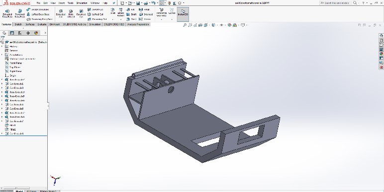
Figure 4. Is the first leap into designing the bottom piece of the German 302 goliath tank.

Figure 5. At some point I knew I was going to have to create a gear that mimics the Tamiya so to start of easy, this is the first design of the gear I’ve created, based off the Youtube training video I found and the image of a tank that Ridwan showed me.
Conclusion:
While waiting for the electrical components I need to check the dimensions of the pieces themselves to make sure it all fits together. For this iteration specifically I know I’ll be needing to change the dimensions of the gear because the spikes are too think for the treads we have.
4th Iteration: March 20th, 2018
Introduction:
Things are starting to pick up in terms of design and trying to get a print available for my team. I managed to connect with maker’s society and access their 3D printing farm so my hope for the upcoming weeks and until the end of the semester is to have an appropriate turn out rate for the 3D prints of the iterations.
Details:
For this iteration, my goal was to have something for the group to work on before the break. I would like to start with the separate hinge pieces, I decided to try a different design, something new, because the previous design didn’t work as well as I thought, the wheels that I would have had to make for the previous design would have been too thin and too small in terms of diameter due to wheel bite. As for the rest of the side, I modified the “ee400d4thsidepart[s]” to look exactly like the previous semester but still implementing the hinge concept in terms of separate pieces and separating the wheel placements above the piece. The spacing in between the top and bottom wheel placements are different which is why I have two different wheel sizes

Figure 6. This is the second attempt at making a hinge that could work underneath the main side piece.

Figure 7. The spacing in between the top and bottom wheel placements are different which is why I have two different wheel sizes.
For the center console, I would like to first point out the hole in the “ee400dmiddleconnector” piece. The reason why I put that gap there was to help create space for the components that we put inside the tank, which is why there is also a hole in the center side pieces as well. For “ee400d4thbotpart” the only difference I made was the opening at the back of the tank for the micro-USB cable to run through. Lastly, for the top I was told there was a possibility of using a UV sensor in our tank so I created an opening for the sensor to go through and I also tried to mimic the placement of the panel openings on the German 302 goliath tank found online and previous models.
Conclusion:
I hoping this design will work out in terms of the hinges and the opening on the sides of the tank to fit all of the electrical components. At this point in time, my group is still in the coding phase and building the PCB so I’m still not sure on what they are implementing and integrating into this design. My goal for the break was to create at least the center console for the rest of my group to figure out how to place the rest of the components inside the vehicle so that way when I got back from break I would have something ready for them.
5th Iteration: April 5th, 2018
Introduction:
Over spring break, even though I was out of town, I was able to get my Solidworks program on my computer to work and came up with a model ready to print by the time I got back. For this new design, I was advised by both Professor Hill and Ridwan to follow the images of “Monkeyfab’s” Goliath tank model. After doing a little bit of research, I had to size it down and change a few components to accommodate for our size restriction and location of our electrical components but at the same time followed the new design.
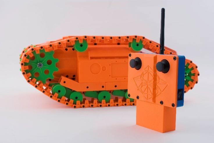
Figure 8. The Goliath tank was following inspiration from the MonkeyFab design.
Details/ Modifications:
Before spring break, I practiced on how to make gears so I did a little research on my own and from that I created the design that’s shown in this folder. The reason why I chose to follow the design of Tamiya’s gear is because I wasn’t sure if I would have enough time to create and print all of the pieces for the treads so I stuck with the gear that resembles the look of the parts provided in the kit from Professor Hill.

Figure 9. A copy of the Tamiya gear design with the adjust length of the spikes so that it catches the tracks better.
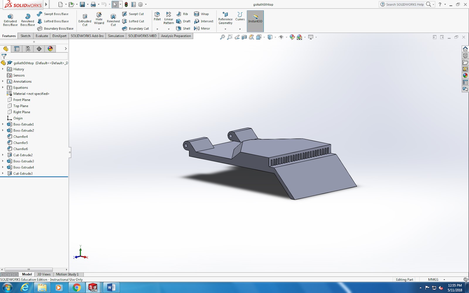
Figure 10. From that I moved onto the top piece and again I tried to mimic what I saw in the monkey fab photo and was able to recreate the look. I didn’t have too much space but I resized it to fit on our tank and look like the part.
From that, I moved onto the top piece and again I tried to mimic what I saw in the photo and was able to recreate the look. I didn’t have too much space but I resized it to fit on our tank and look like the part. As for the hinges, again space was a concern and I wanted to have a strong hinge so I put those parts on top of the piece extending outward which would connect to the bottom piece which was modified to accommodate for the new hinge.
Lastly, the “5thiterside piece” has an opening towards the back of the piece which lines up with the motor placement. The holes along the lower perimeter of the piece were my idea of finding a way to attach the side pieces without getting in the way of the closing hatch. One of the things that I had to think about was how to efficiently keep the lid closed on the tank.

Figure 11. This is a side view of the side piece used on the center console. The wholes along the bottom edge represent the pin locations to keep it closed.
Conclusion:
One of the things I realized while researching this new design was that there were no “stl” or “solidworks” files for any of the parts shown in the monkey fab design. I was able to find multiple images which gave really good insights on what the pieces look like, but none of them gave concrete dimensions on the size of their tank. Also their gear system is a lot different than ours which is why I don’t have an additional piece on the side of the tank behind the green gear in the picture above. Overall, there was not much to go off of but I did end up scaling the image above and was able to produce a center console close to what the tank looks like now.
6th Iteration: April 12th – 16th, 2018
Introduction:
After my first attempt in trying to design parts of this new model, I tried putting it all together and noticed a couple things wrong with the prints. I also put my focus on all the pieces that were going to be implemented to make up each side of our tank.
Details/Modifications:
Since last week, I’ve made some pretty big changes to our model. Starting off with the bottom of the tank I added two tabs on each side of the bottom piece that has a 3mm diameter hole to screw the corresponding holes on the “sidepiece041718” to create the center console. This will allow the side walls of the center console to have a better connection to the bottom piece and create a sturdy tank. The other difference I would like to point out on the same piece is that I moved the hinge from being on top of the tank to becoming a part of the top and making the hinge flush.
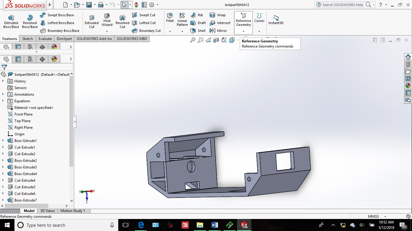
Figure 12. Here is the 1st iteration of the bottom piece from the new model.
When designing the new model, there seemed to be a lot of parts in the image provided to create the side piece. First off I created the hinge holders in two separate pieces to resemble the design. One is the front and the other the back, designed to each hold two hinges. These two hinges would then be screwed underneath “centersidepiece” along the outside edge to resemble the look. The “bsidehingeholder” is meant to fit completely underneath the center side piece with only the lower half of “fsidehingeholder”. The angled portion of “fsidehingeholder” is mean to hold the “motified bottom hinge041618”. The new wheel holders are meant to hold two thin wheels created earlier this semester on either side at 5mm in diameter and 2mm in thickness and on the end with the small tab.

Figure 13. This is the front end of the side hinge holders that will be screwed under the center side piece along the outside edge.

Figure 14. This is the center side piece that makes up the majority of the side of our tank. The circular and rectangular indentations represent the design of the tank used in the 1940’s.
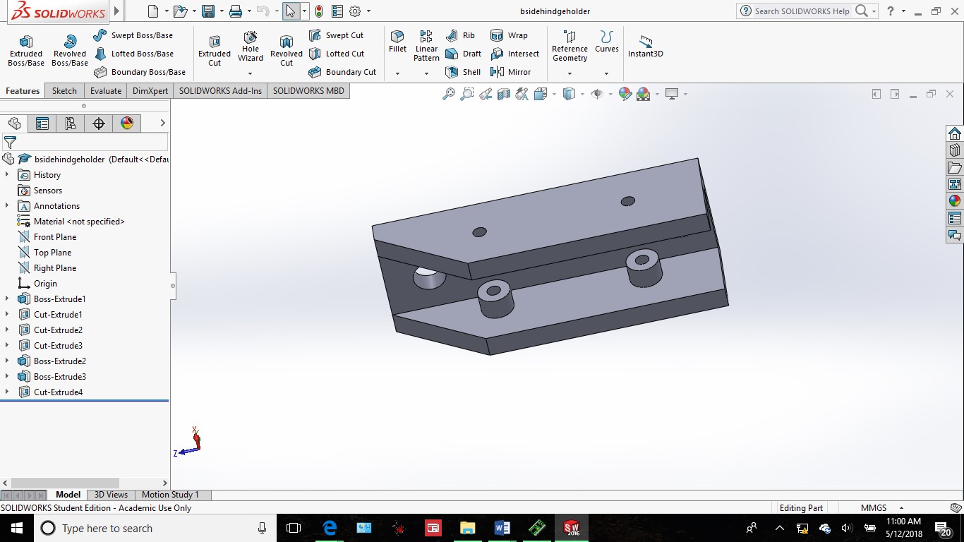
Figure 15. This is the back end of the side hinge holders that fits perfectly underneath the length of the center side piece along with the other hinge holder Figure 13.
As for the gear, I used what I learned from the first attempt to create this second-gen gear and try to follow the Tamiya design provided by Professor Hill. With this gear I also had to modify the size of each part. For example, the diameter for the motor to go through was a little more complex than just a circle so I created a shape that would catch onto the flat side of the motor bit and rotate as needed. The spikes were also altered in a way that would extend them out a little bit further to better catch onto the treads.

Figure 16. The circle in the center of the gear is not a perfect circle which is designed to catch the flat end on the motor pin.
Conclusion:
These new pieces should bring our team that much closer to completing the design. I hoping that when these pieces print that they all come out fine and work the way they should. One of the other things I have to think about in the upcoming week are the attachments/placements for the springs.
7th Iteration: April 18th, 2018
Introduction:
Last week I managed to create and print the majority of our parts for this design A few problems that I ran into this week was with the printing properties mainly the quality of the overall print. Even though the printer can print at 50 microns, there was one component in particular that I wasn’t aware of being too thin. Which lead to some changes that I made this week.
Details/ Modifications:
For this Iteration, there wasn’t that much of a difference from previous methods but the hinge on both the top and bottom pieces of the center console were too thin to maintain a solid hold on each other. After the print and while attempting to put it together the hinge started to break. Because of that, I designed the hinge to be thicker than the model before approximately 1mm all around compared to 0.5mm. I also wanted to point out that this was the first design in which I implemented a trade-off study, specifically the hatch closing feature which has two pieces that extend from the top and snaps closed on the corresponding grooves on the bottom piece.
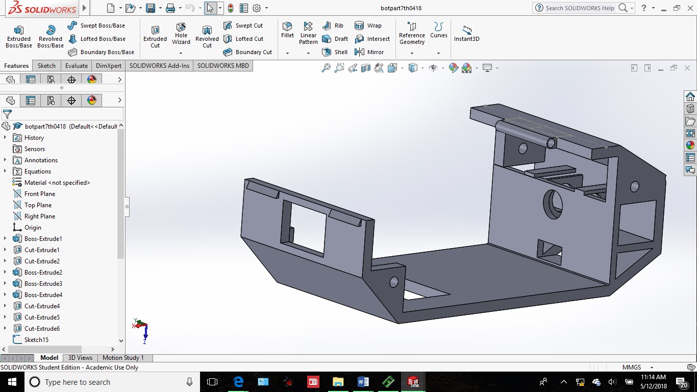
Figure 17. The tradeoff study being implemented on the front of the bottom of the tank shown with the two rectangular triangles on either side of the range finder opening.
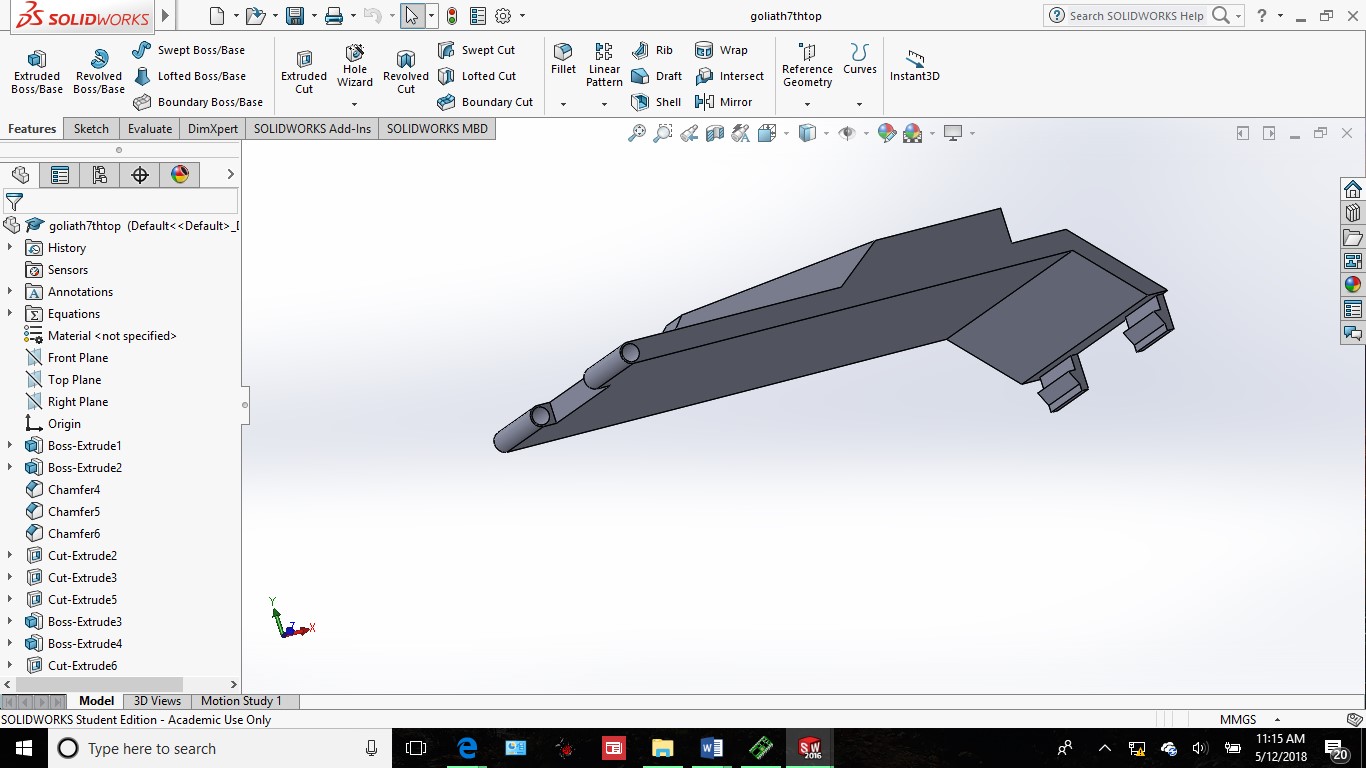
Figure 18. The same study being implemented on the front of the top of the tank, but looking at it from the back.
Thanks to Ridwan’s casing for his caliper, I thought of an alternate way to close the lid. His storage case for his caliper has two snapping pieces the keep the box close, which in turn lead to the closing features I added to my design. The reason why I made two tabs was because I didn’t want the lid to get in the way of the range finder. Lastly, there still wasn’t any notifications on the orientation or placement of the 3dot board which is why I don’t have a set or fixed location for the electrical components.
8th Iteration: April 19th, 2018
Introduction:
After making the modifications last week I found that there was still some more work to do. This week I focused on modifying the tank to some of the components we had just bought from McMaster-Carr and Sparkfun.
Details/ Modifications:
For today’s rendition of the bottom piece, I changed the size of the opening for the range finder in the front. For the bottom hinge folder towards the back, I added two points for which the springs from McMaster will connect. For the other hinge, I did the same, but I also extended the length of it to accommodate for the minimum size provided by McMaster-Carr.

Figure 19. Identifying the small tabs along the length of the back side hinge holder two rectangles placed.

Figure 20. Due to the length of the springs from McMaster –Carr I needed to adjust the placement of the tabs on the front side hinge holder as well.
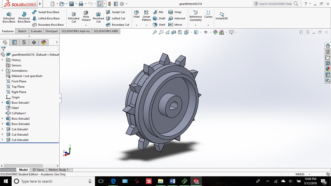
Figure 21. Changed the length of the gear spikes to a finer point and subtracted 0.5mm.
I noticed after the last print I made that the spikes on the gear held onto the treads too long while rotating. To fix this problem I changed the length of the spikes but tall enough to efficiently run the tank. I also changed the diameter of the placement for the motor pin. Previously, I took an exact measurement on the motor pin and matched that on my gear but I found that, due to melting properties I had to make the hole a little bit bigger.
Conclusion:
I’ve realized that when using multiple printers as your source of production, it is hard to determine the right size for every piece every print. Every printer has a different effect on the material we used to print. I’ve noticed that so far I’ve used four different printers between Ridwan and the 3D printing farm at maker’s society.
9th Iteration: April 23rd to 25th, 2018
Introduction:
It’s getting towards the end of the semester, luckily, this week I got some details on the dimensions of the electrical components that we’ll be using inside of our tank. So my focus for this week after talking to Professor Hill is to get an idea of how I’m going to mount the electrical components to the chassis.
Details/ Modifications:
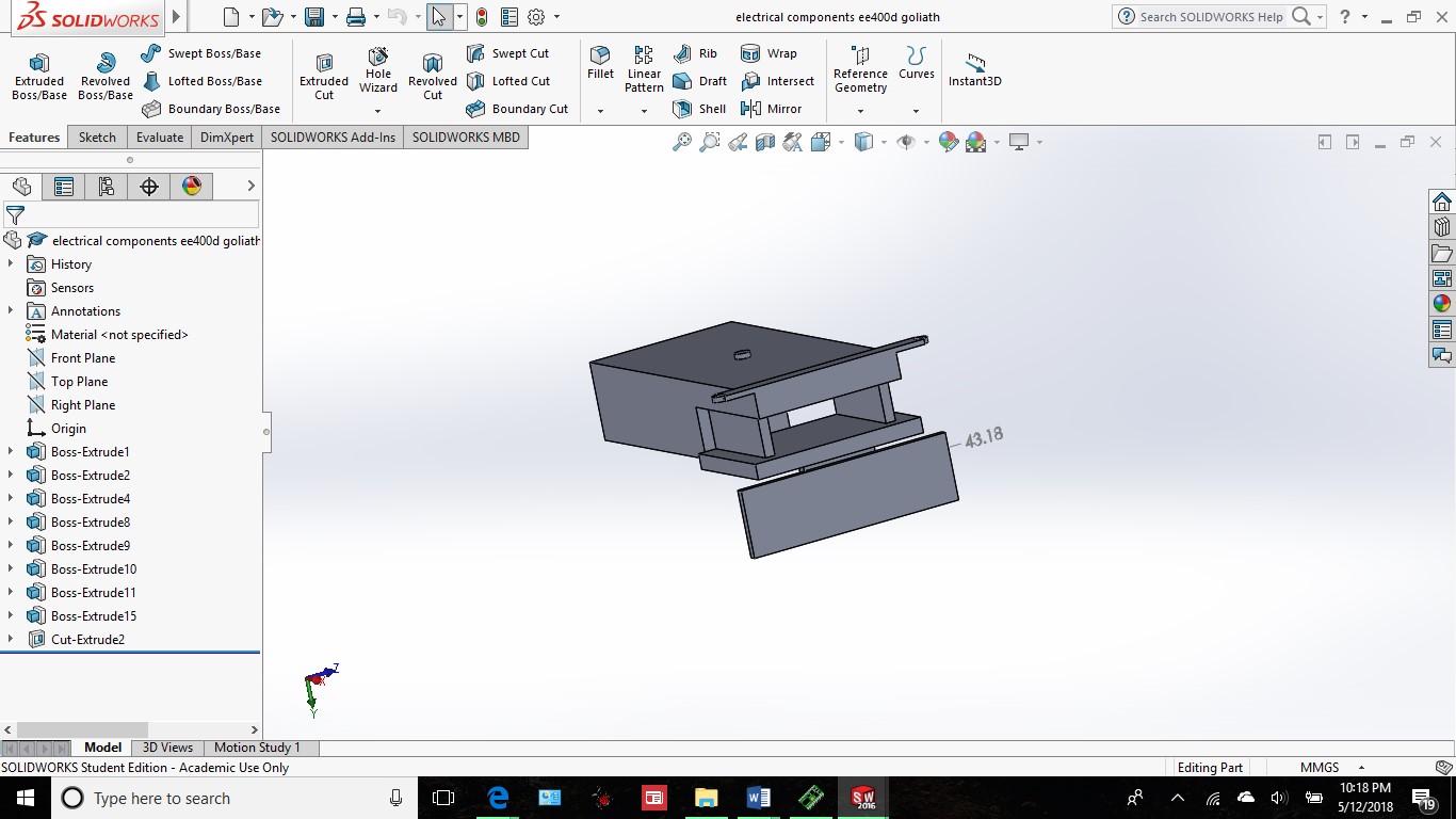
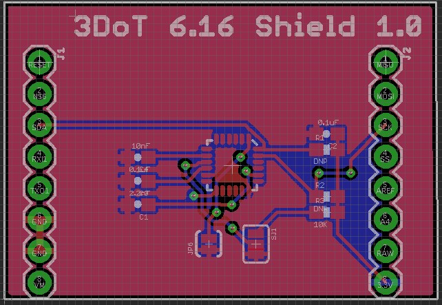
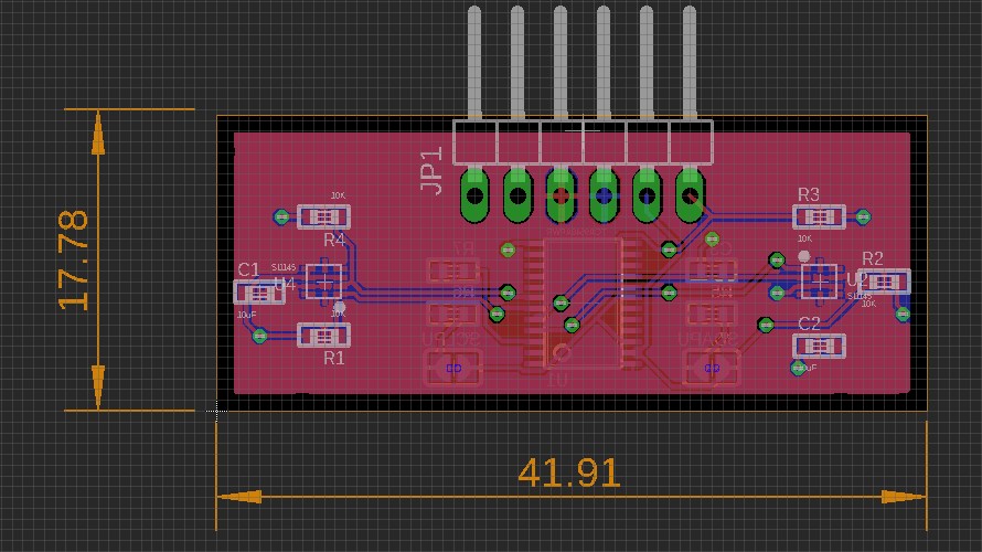
Figure 22. Top view of all of the electrical components. And the 43.18 represents the length of the proposed PCB.

Figure 23. This is the bottom side of all the proposed electrical components connected to each other.
Today on the 23rd I was told about the electrical components and their exact dimensions. The biggest piece of the electrical components resembles the 3dot board, provided by Chris H. at 3cm x 7cm. The next larger, thicker rectangle resembles the size of the battery that would be on the board. Next, are the two female pins that are holding the PCB over the 3dot board and the range finder that is connected to the PCB. Concept option suggested by Professor Hill.

Figure 24. The holes at the bottom of the center side piece serve as a guide to the placement of the screws to combine the hinge holders to the center side piece.
For the center side piece, I had to adjust the placement of the screws and hinges which then lead to re-printing the rest of the side pieces. Before the screw points were centered onto the piece, with this new layout I moved them more to the flat end, rather than the cut off end, to extend the length of the hinges and to allow more space for the moving parts as seen in the picture of the original design. I also changed the width of the material surrounding the holes on the previous design to 1mm as shown on “wheelholder9thiteration”.

Figure 25. Had to adjust the width of 3D printing material that surrounded the holes so that way it didn’t print weak and breakable hinges.
As for the center console, I added a screw point just to test and see where I could line up the 3dot board in reference to the top (a piece that will be removed/ modified later when I get the exact dimensions and the physical parts). Lastly, there was a small change on the side piece in which I added a 3mm diameter hole for the other tank wheels to go through.

Figure 26. Wanted to show the addition of an extra hole to serve as a guide to the rolling wheels opposite of the gears.
Conclusion:
As we move towards actually demoing and implementing our electrical components I noticed that there is about a 2cm gap between the placement of the electrical components and the bottom of the tank. Further iterations at this point depend on how the prints come out and whether or not the group and or instructors see any changes that could be made.
10th Iteration: April 26th –April 30th, 2018
Introduction:
As it’s getting close to the end of the semester, I’m looking to finely tune specific parts to get our tank looking like an actual model. Over the past week, I was able to create a secure position for the 3dot board and my hope is to have a physical 3dot board ready for the next print.
Details/ Modifications:
As our tank is getting closer to our final design, I had to play around with the length of the hinge holders to make sure I had space for everything. For example, the small tabs that lead to the springs on “10thiterbsidehingeholder0430” moved closer to the hinge to avoid being broken off. To make sure the width between the wheels matches the width of the guides on the tread I modified one of the older designs to change the thickness of the wheel to 2mm.
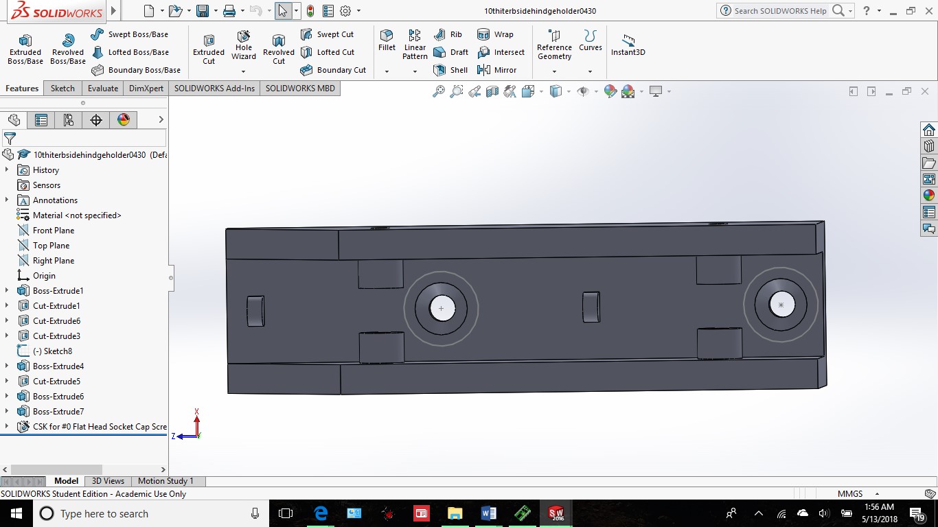
Figure 27. After the print I realized I had change the placement of everything a little bit by making more space for the springs.
One of the key new features that I added to my tank is the mounting points for the 3dot board on the “goliath10thtopwhinge” piece.

Figure 28. The electronic components file is the same as before but this time I added two points on the front end of the lid to screw the pieces on and the two groves in the back used as guide and placement of the back end of the electrical components and securing it to the lid.
In terms of the bottom piece, I had to change the placement of range finder viewpoint to work with the modification of the top piece and location of the electrical components. I also moved the location of the line following sensor opening closer to the front to line up with the electrical components on the lid.
Conclusion:
After the prints were made, the plain 3dot board used in previous semesters given to me to test and see if the board fit. Due to false information, the width of the board was actually larger than I was previously told. Along with other parts, I’ll be making some more modifications and prints in the next couple of days.
11th Iteration: May 3rd, 2018
Introduction:
After making a few modifications earlier this week I was able to quickly get the prints from Maker’s Society, but some of the parts I made didn’t really seem to fit the way I wanted it to be. For example, the dual hinge had a while biting problem so I played around with different lengths. The spacing of everything underneath the center side piece needed an adjustment as well.
Details/ Modifications:
Starting off with the dual hinge, had to adjust the overall length of the piece because it was too close to the hinge holder and gear. My solution was to extend the piece above the two-wheel pin locations by 5mm (12.5mm total) then realized that it was too long so I decided to take off 3mm and changed the length again to 9.5mm.
The next couple of parts I would like to talk about are the front and back side hinge holders. In all of the previous designs, I was concerned about the spacing for the hinges and screws. In this design, I feel like I have figured it out in the sense that I put three of the tabs for the springs on the “11thiterbsidehingeholder” moved the screws and adjusted the spacing on “fsidehingeholder11th”.

Figure 29. This is the back side hinge holder that extends past the length of the bottom edge of the center side piece.
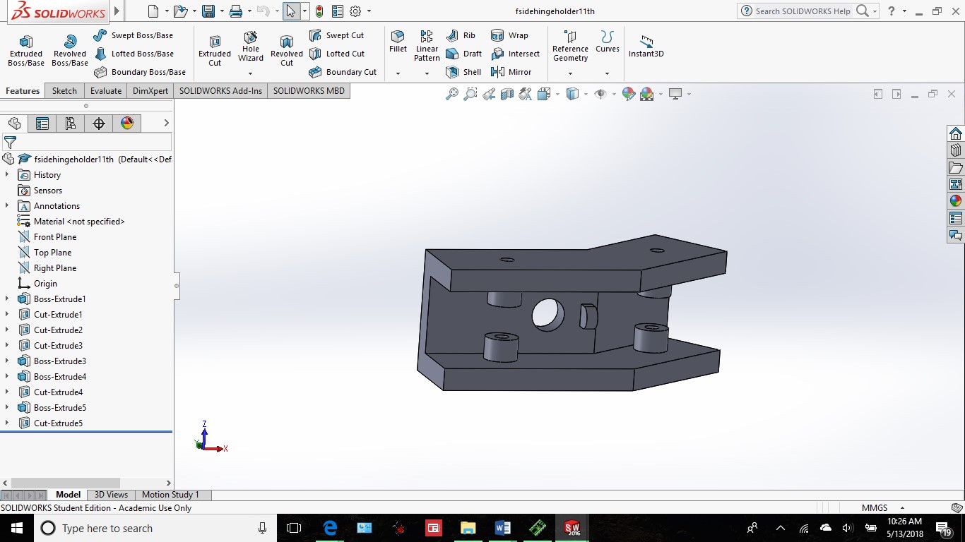
Figure 30. This is the front side hinge holder which will be angling towards the gear.
For the center side pieces, I also realized based off my Solidworks knowledge capabilities that I can’t mirror sketches and the hole locations on an entire piece. For that reason, I created two center side pieces in order to solve that problem. On this same piece, I coordinated the new screw locations on the side hinge holders to the bottom of this piece.

Figure 31. The adjustment made to creating space for the 3dot board mounted to the top of the center console.
The “goliath11thtopwhinge” piece has only one small difference, I increased the gap of the 3dot board holder by 2mm to adjust to the actual dimensions of 3.5cm in width. It is now 33mm in width from the part’s base. The reason why I made the gap 2mm smaller than the actual size was that I wanted a tight fit and I had the width of the top piece as a size constraint if the parts were any smaller they could break off easily. I also adjusted the length of the top piece by 0.5 mm to make it easier to open the lid of the center console. I also created the rolling wheels that would be opposite of the gears on the tank. I also included the screw points of the center side piece to the “sidepiece11th”.

Figure 32. The four hole in the center off the side piece represent the locations of all the screws that will hold the center side piece up.
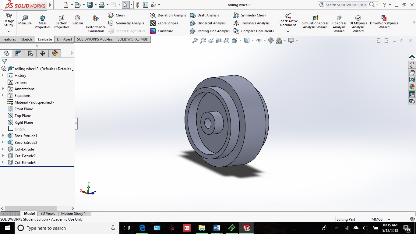
Figure 33. This is the 3D rendition of the wheels used on the opposite side of the gears.
Conclusion:
Although I have all the parts printed, I’m not too stoked that there are different colors in the design. If there is enough time, I’ll be looking to make everything the same color. Between the size constraint of the springs from McMaster-Carr and the size constraint of the tank, the center console sits a little too high above the ground compared to what I wanted. In this upcoming week after the remaining prints, I’ll be looking for any last minute modifications that need to be made.
12th Iteration May 10th, 2018
Introduction:
This is crunch time, it’s cutting it close but there some very important changes that needed to be made. For this last iteration of my design, I edited quite a few pieces. Pieces in which I’ll discuss in this blog post.
Details on Modifications:
First off, there were a couple of things that didn’t need changing, but a reprint. For example, the “11thiterbsidehingeholder” and “fsidehingeholder11th” is correct in terms of dimensions and design but for some reason, the piece was warped and wasn’t flushed with the outside edge of the center side pieces. Also, the gear and wheel holders were printed in a different color (pink) so I asked for a re-print to match the color scheme.
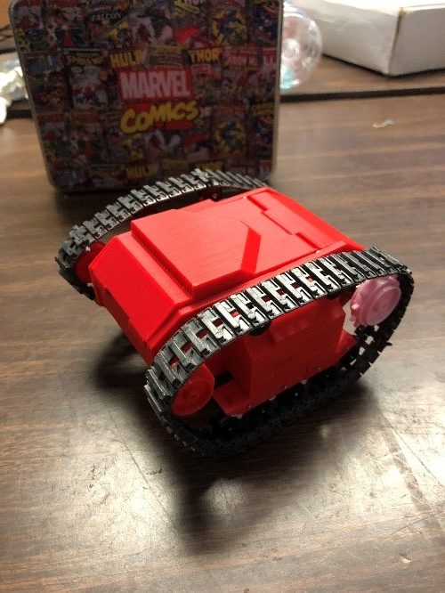
Figure 34. Top view of the 11th iteration of our tank.

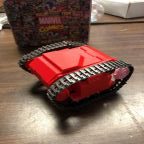
Figure 35. Side view image of the tank, it’s kind of hard to notice, but the tank rides pretty high off the ground.
For the center side pieces, the orientation of the squares and circles on the outside face were backwards so I fixed that to match the model below. As for the dual hinge, the arm was still too long so I adjusted the length to allow the wheels to fall just below the “fsidehingeholder11th”
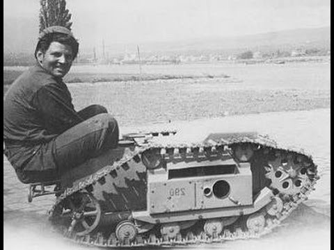
Figure 36. A photo of an actual German 303 goliath tank from WW2 in 1942. Also known as the “doddle bug” by the soldiers at that time.
Moving on to the center console. The orientation of the front of the tank and the gears is going to be a bit backward, but it should still work all the same. In the previous iteration I had the gear and the “rolling wheels” leveled with each other, but that doesn’t match the 303 goliath model it looks more like the 302. For that reason, I extended the face with the range finder port to about 27mm rather than 20mm and I made the tabs towards the front of the bottom piece a bit larger to accommodate for both the screws to go through above the hole for the bushings and bring the axle lower to get that 303 look. For the top piece, I followed Professor Hill’s request in making only one tab to snap the center console closed. The only reason why I had two before was to make sure the range finder can “see” between the two tabs.
Lastly, for the flat side pieces, I relocated the corresponding holes to the bottom piece of the tank and created a housing to cover the exposed motor piece on either side. I also adjust the lengths of all the edges to match the perimeter of the center console.
Conclusion:
For the number of iterations that I went through, this project really enhanced my solid works skills and my ability to adapt quickly to changes. For example, after making these last modifications I realized I received some poor quality prints but was able to redesign them fast enough to get a new printed model. For the next semester, my recommendation would be to try and find a good way to fit both the range finder and the motors on the same side. I’m hoping that with my submission my files can be accessibly viewed by others to take the next step forward.
References
- http://www.monkeyfab.com/goliat_sterowanie/
- Figure 36 was from a youtube video
- https://www.solidworks.com/

