Written by Ernie Trujillo (Project Manager), Ryan Nguyen (MST Engineer), Tai Nguyen (E&C Engineer), Milton Ramirez (E&C Engineer), and Daniel Guerrero (M&D Engineer)
Mission Objectives
Written by Ernie Trujillo (Project Manager)
The main objective of the Goliath Tank is to navigate through a maze, first, controlled by the User and, second, autonomously playback the unique path initially input by the User. Afterwards the Goliath Tank will be tested in terms of avoiding collisions with other robots if they happen to interfere with the path required to be traversed by the Goliath through the maze. As far as mission constraints, the team will be required to use the Arxterra App to program the robot to navigate and playback the unique path through the maze given by the User.
For more detailed information of the Customer expectations and Mission Objectives, proceed to the link provided below:
S’18 Project and Mission Objectives
Level 1 & 2 Requirements
Written by Ryan Nguyen (MST Engineer)
Level 1 General Requirements
- The robot shall be completed by May 15
- The robot that is to be designed shall be done in such a way that it is relatively inexpensive, less than $250, preferably a laser cut model or 3D printable design.
- Since robots are to be operating the maze simultaneously, the design should ensure that collisions are to be avoided in all situations.
- When printing 3D models for the project, any prototype print shall obey the 2/2/2 rule and shall take no more than 6 hours in sum. Projects may request a waiver with justification.
- Robots shall utilize a version 6 3DoT board powered by the 3.7V RCR123A battery. Projects may request a waiver with justification.
- The robot will be designed in such a way that there are no dangling or exposed wires. Connectors will used between all electronic and electromechanical components. Jumper wires will not be used, ribbon cables are preferred; gauge of wires should be consistent with current.
- Good construction techniques: all moving and rotating parts shall use bushing or bearings, hinges shall be interlocking and include a latching mechanism. No gaps shall be greater than 1 millimeter, immediate access shall be provided to all external connectors (USB, switches).
- The robot shall record the user’s input and be able to repeat the previous route defined by the user. The software algorithm is defined in 400D E&C lab sequence.
- During teaching mode, ArxRobot app via mobile devices shall be used to teach the robot to navigate the maze.
- During playback mode, the ArxRobot app shall transmit live video feed and telemetry to the Arxterra control panel, including battery level.
- The Robot disassembly time shall be 10 minutes. Projects may request a waiver with justification. All 3Dot boards will be clear of electronics, motors will be disconnected, all sensors will be disconnected.
- Reassembly time shall be 10 minutes. Projects may request a waiver with justification. All teams will be allowed to use a cable tree as well as an assembly diagram as necessary. All robots will be tested after reassembly to confirm its functionality.
Goliath Level 1 Requirements
Project L1 Requirements
L1 – 1 The Goliath will drive on flat surfaces, such as cloth, paper, linoleum.
L1 – 2 The Goliath shall be operational for 1 hour duration.
L1 – 3 The robot shall be a scale replica of a Goliath 302 Tank. The scale factor will be 1:11.5 with a mean
square error (MSD) over all three axis (x, y, z) of no greater than 10%.
L1 – 4 The total cost of the goliath shall be no greater than $200.
L1 – 5 The Goliath shall have easy access to charging and programming hookup.
L1 – 6 Goliath shall house a custom PCB and use control telemetry shall to navigate the maze.
Program L1 Requirements
L1 – 7 The Goliath should make tank noises.
L1 – 8 Goliath shall detect and avoid other robots in the maze.
Goliath Level 2 Requirements
System L2 Requirements
L2 – 1 The mass of the goliath shall not exceed 400 grams. Goliath L1-3
L2 – 2 The goliath shall be smaller than 5x4x3 inches. Goliath L1-3
L2 – 3 Goliath shall use IR range finder to detect objects. Goliath L1-7
L2 – 4 Goliath’s final version shall be printed with ABS plastic. General 3
L2 – 5 The Goliath shall be power by a single 3.7v RCR123A battery. General 6
Subsystem L2 Requirements
L2 – 6 Main PCB shall have two UV sensors, UV LED, Gyro, and connectors to range finder. Goliath L1-6
L2 – 7 Arx-robot App will have different operating control modes and direction pad to control Goliath’s
movement. Goliath L1-6
L2 – 8 Goliath shall have 4 x 10 mm cut out on back of goliath to provide access to charging and
programming hookup. Goliath L1-5
L2 – 9 The Goliath will not have any electrical parts mounted outside. General Level 1-7
L2 – 10 The Goliath should have a latched lid. Interlocking mechanism. General Level 1-8
L2 – 11 The goliath shall detect objects in an 10 inches in front. Goliath L1-8
L2 – 12 Goliath will have all-terrain tracks. Goliath L1-1
L2 – 13 The goliath shall have 10 gears. Goliath L1-1
L2 – 14 The goliath shall have 2 motor(s), located in the back of the chassis. Goliath L1-1
System Block Diagram
Written by Ryan Nguyen (MST Engineer)
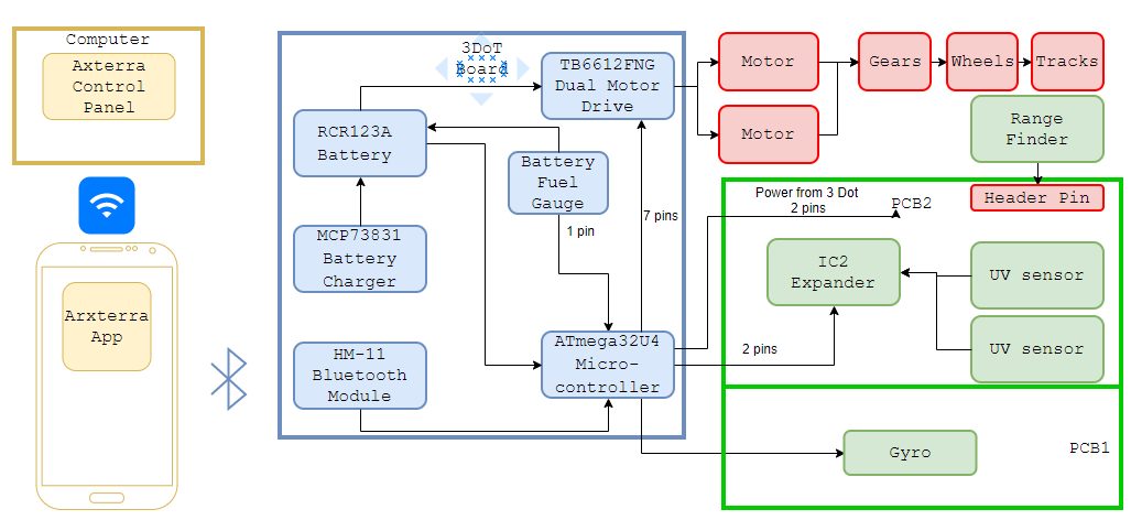
Figure 1 – System Block Diagram for the Goliath Tank.
The system block diagram illustrates how components of the Goliath communicate and connect with each other; from the control panel that uses Wi-Fi to talk with the mobile app to the wheels and treads. More detailed specific components such as the HM11 Bluetooth model is added, and various parts on the PCB parts are laid out; more items are expected when the E&C engineer completes trade off studies. The 3DoT board houses a rechargeable battery that powers the motor driver and the Atmega32U4, which in turn powers the PCB. Number of pins are listed to demonstrate a rough idea of how many pins are required and create rough layout for the interface matrix.
Work Breakdown Structure
Written by Ernie Trujillo (Project Manager)
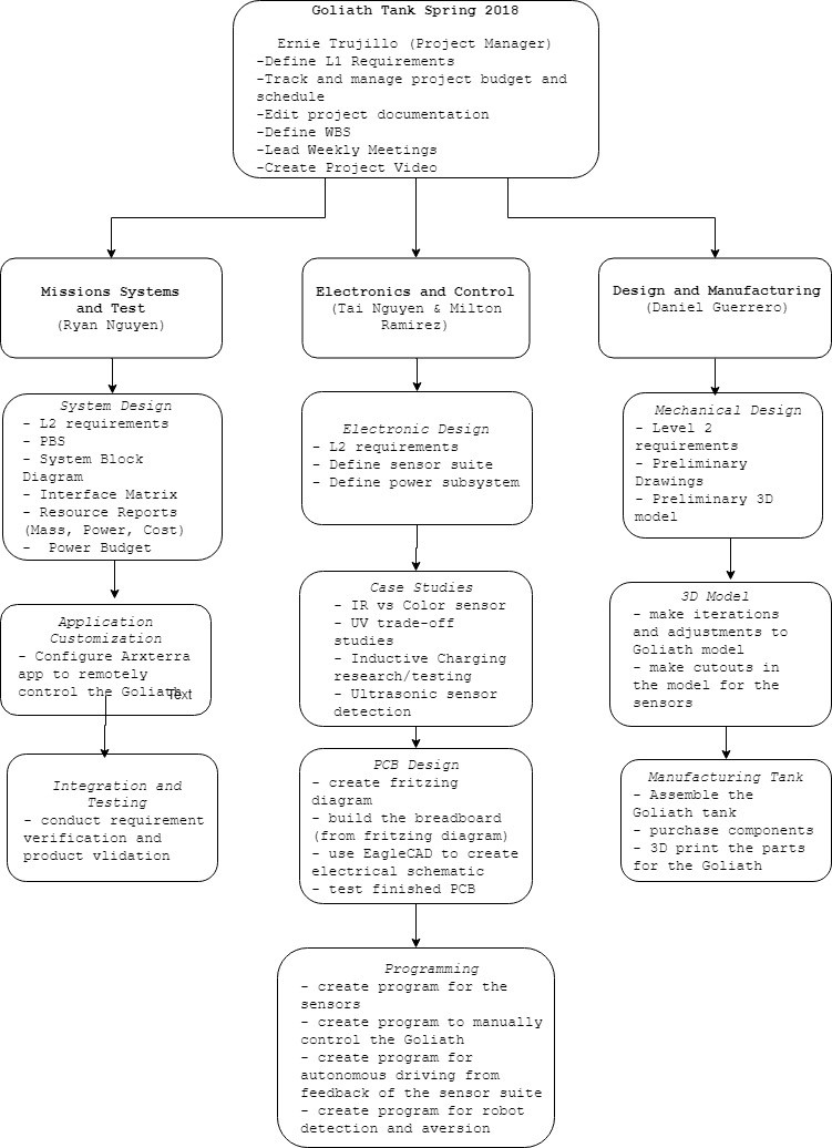
Figure 2 – Layout for the Work Breakdown Structure of the team members.
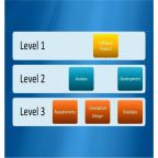
The Work Breakdown Structure (WBS) provides organization for the tasks a team is required to complete for a project. For the Goliath team, the WBS offers a general overview of the objectives that every team member is required to do. The tasks are broken down in terms of the type of engineer (MST, E&C, and M&D) and then within each field it goes into further detail as to what each position’s tasks entail. This diagram offers each engineer a quick overview of the responsibilities that their position takes on.
Product Breakdown Structure
Created by Ryan Nguyen (MST Engineer)
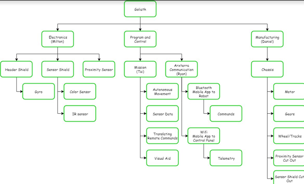
Figure 3 – Diagram of the Product Breakdown Structure.
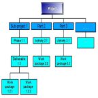
Like the Work Breakdown Schedule, the product breakdown schedule breaks down the products and the personnel responsible for them. In the spring 2018 project, the Goliath is broken into three products: Electronics, Program and Control, and Manufacturing. All components such as shields and sensors are the responsibility of Milton, as they go on the custom PCB. Tai creates the programs for movement and ultimately completing the mission. Ryan takes care of the communication between the mobile App, control panel, and robot. Lastly, Daniel fabricates the Goliath.
Interface Matrix
Written by Ryan Nguyen (MST Engineer)
The interface matrix shows how each subsystem of Goliath connect to the ATmega32U4 microcontroller. The top header consists of the sub-systems, the left column has the name and pin number of the ATmega32U4. The matrix maps out how each pin is connected.
From the ATmega32U4, the version 6x 3 dot board specifies 16 pins that students can use for their robots. The first matrix shows the two PCBS of Goliath that will be connected to the three dot board, the top header shield, and the front sensor shield.
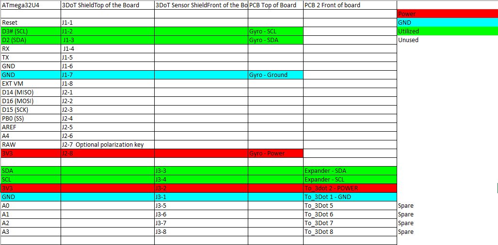
Figure 4 – Interface matrix of ATmega32U4
The second matrix shows how the components on the sensor shield will be connected; Goliath uses two UV sensors, as well as a range finder to navigate the maze.
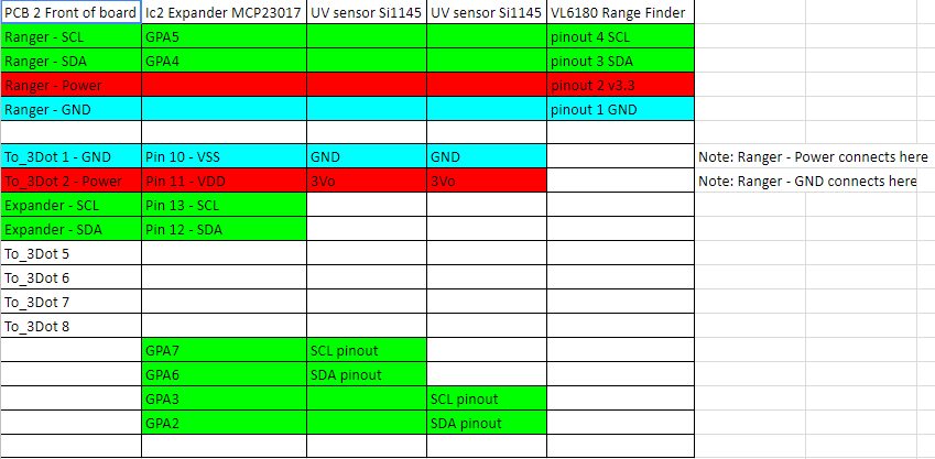
Figure 5 – Interface matrix of front sensor shield
Lastly, Goliath uses a gyro, connected to the top PCB, to determine turning in the maze.
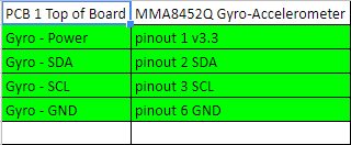
Figure 6 – Interface matrix of top header shield
Fritzing Diagram
Created by Milton Ramirez (E&C Engineer)
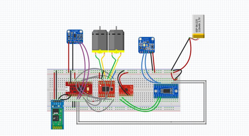
Figure 7 – Fritzing Diagram for the Goliath Tank.
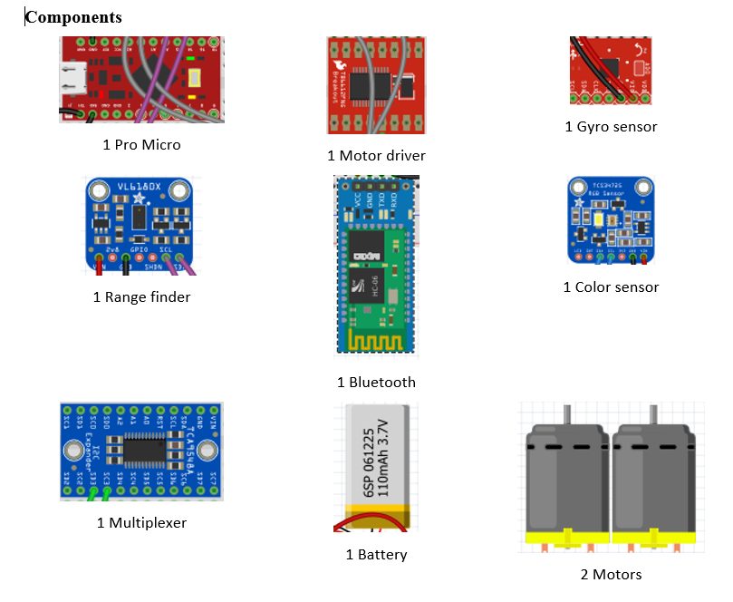
Figure 8 – components used for the Fritzing Diagram.
This a prototype of how we will connect the parts we are going to use and some of these parts might not make the final design. In this prototype our processor will be the pro micro instead of the 3Dot board since Professor Hill is still working on the 3dot board. Also, for that same reason we will have to use Bluetooth circuit for our prototype since the 3dot has Bluetooth implemented in it. We will probably have to use this configuration for most of our testing since we won’t get the 3dot until later in the semester. We also have a motor driver to control our motors. Then we are using a multiplexer for our sensor which are a Gyro sensor and a color sensor. Then we also have a Range finder and this and the color sensor are floating outside on purpose because the color sensor goes in the bottom of the goliath and the range finder we be somewhere in the front. Also the specific part number are not include since that will also change for the last design.
Mechanical Drawings
Written by Daniel Guerrero (M&D Engineer)
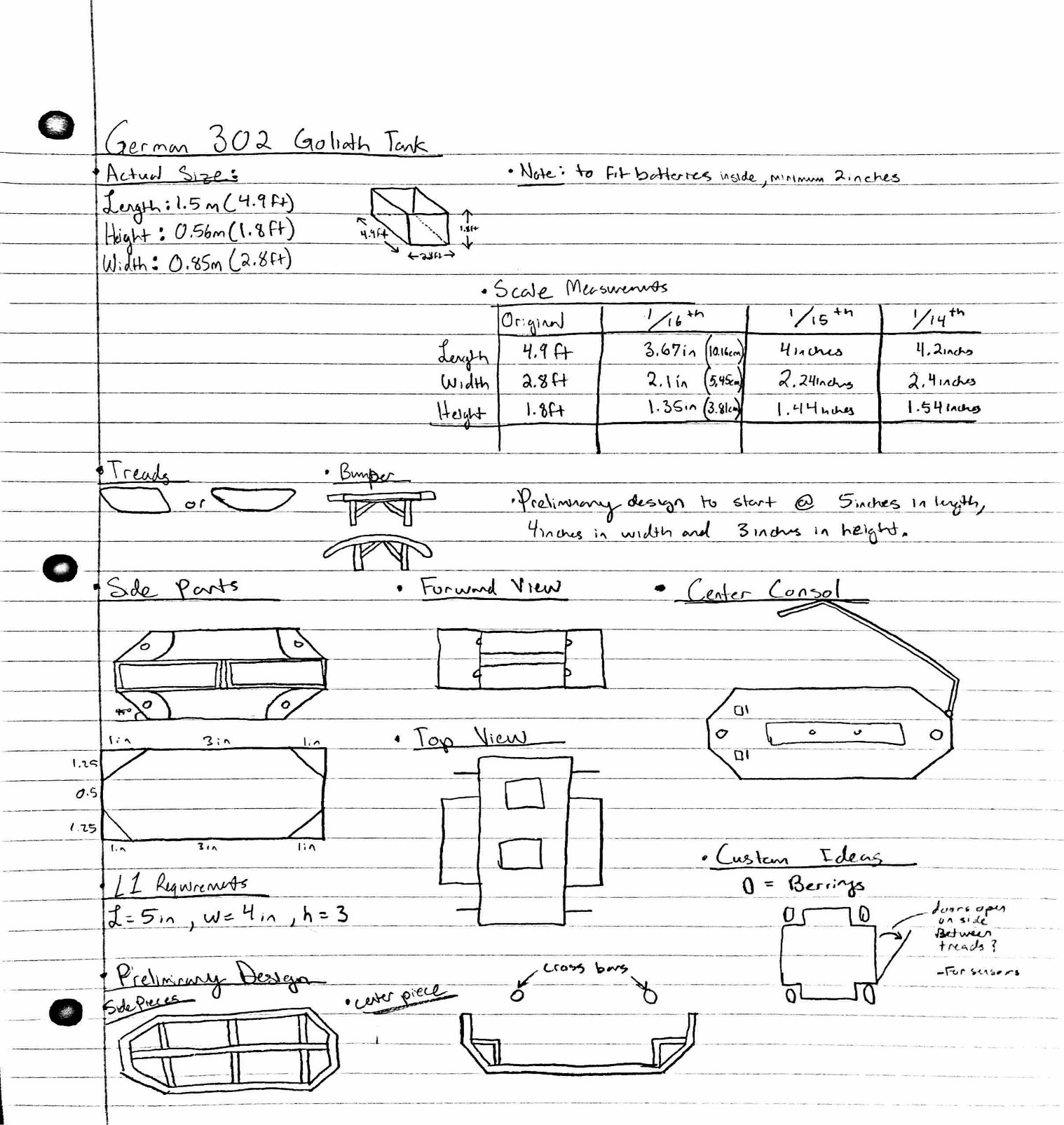
Figure 9 – Preliminary sketches for the Goliath Tank.
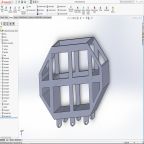
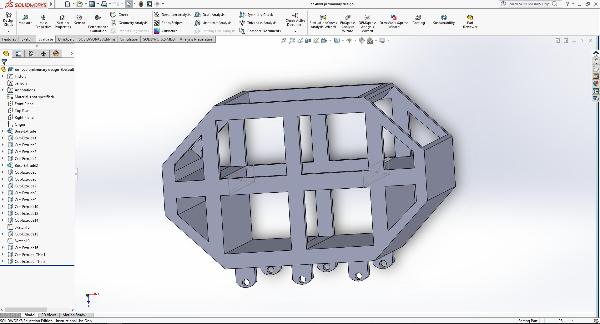
The reason behind this design was to follow the concept of the spring 2016’s design to create a box shell of the tank as a preliminary design and attempt to fit all of the equipment inside. I tried to steer away from just a simple box for this design and tried to follow the generic shape of the German 302 goliath tank. As for the placement of all the gaps in this design, I was aiming to have it accessible enough to configure all of our equipment into the design. For this first edition I kept the size to five inches in length by four inches in width and about three inches in height.
Resource Reports (Power, Mass, Cost)
Written by Ryan Nguyen (MST Engineer)
Power Report
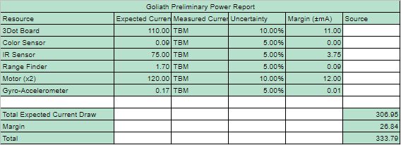
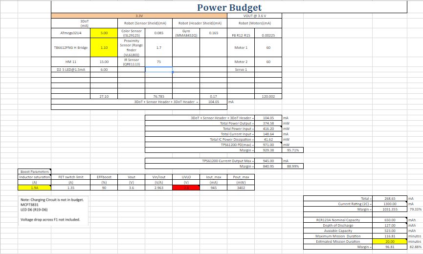
Figure 10 – Spreadsheet for the power consumption of the components.
The power report needs more information in measuring the power draw, this will be done once some sort of system is established for parts such as the 3Dot board and motors. Sensors’ measurements are from data sheets that manufacturer provide. Project allocation comes from the maximum instantaneous current the RCR123A can provide.
Mass Report
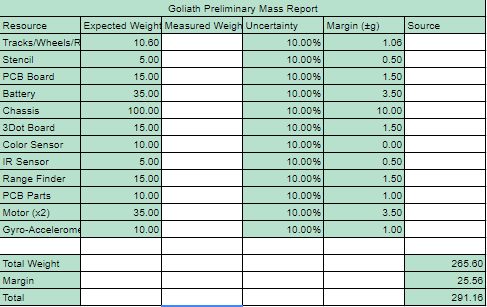
Figure 11 – Spreadsheet for the mass of the components.
Much of the mass report are assumptions, based on visual inspection of parts online. Many parts do not list the mass, such as sensors. It is decided to put 10% margins on all parts as they could fluctuate once the product solidify. Project allocation was based on a requirement that the Goliath shall withstand all impact with all robots; thus the chassis must be quite sturdy.
Cost Report
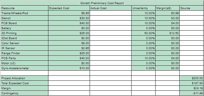
Figure 12 – Spreadsheet for expected expenditures for the Goliath Tank.
The cost report was based from the previous projects, with large uncertainty placed on 3D printing as it is undetermined how many iterations will be printed. Several items are free as they are provided by the class, others are taken from online. Shipping price are considered in uncertainty. Project allocation of $200 dollars was given by the mission objective to make a relatively cheap toy.
Preliminary Budget
Written by Ernie Trujillo (Project Manager)
The customer allotted $200 towards the Goliath Tank project. At this moment, the total expenditure of the project can not be confirmed as the cost for the PCB and the 3D prints designs are unknown. Also, since the definitions of the maze are not complete at this moment, there is a chance that some sensors will be added to the list while others are removed. About 60% of the budget has been established while the remaining funds will be used for the last few parts that will be needed to complete the Goliath Tank.

Figure 13 – Excel spreadsheet for the components needed for the project. (1/2)

Figure 14 – Excel spreadsheet for the components needed for the project and totals and general overview of the project budget. (2/2)
The spreadsheet provides most of the parts that will be required for mission success. (Will be updated to include all the parts) Included is useful information to the team such as the quantity, cost, and link to the part.
Planning & Schedule
Written by Ernie Trujillo (Project Manager)
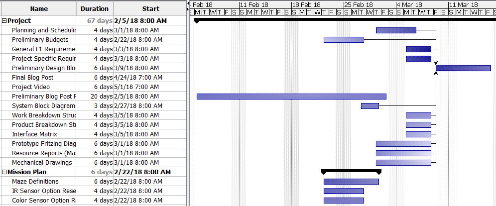
Figure 15 – Gantt Chart , these tasks mainly focus on being prepared for the Preliminary Design Review. (1/3)

Figure 16 – Gantt Chart (2/3), tasks that are pertinent to implementing the hardware to the Goliath.

Figure 17 – Gantt Chart (3/3), tasks that focus on software implementation and final verification of the Goliath.
Broad Layout of Project Schedule
Phase 1 (Research), Weeks 1-5:
- Look through blog posts from prior semesters on Arxterra website for useful information that the current team can implement.
- Begin developing level 1 & 2 requirements to meet mission objectives and customer expectations.
- Begin layout for all tasks required to reach mission success at the end of the 16th
Phase 2 (Preliminary Design Review), Weeks 6 – 8:
- Achieve a thorough schedule to lay out all tasks required to be complete by the team to bring the project to fruition.
- Accomplish preliminary tasks: preliminary 3D model, system block diagram, fritzing diagram, mechanical drawings, resource reports, work and product breakdown structure.
Phase 3 (Rapid Prototyping), Weeks 9 – 12:
- Design multiple iterations of Goliath Tank to make final product more efficient.
- Create program that will integrate all systems that are in the system block diagram. Also, ensure that the program will have the robot operate in a manner that meets mission objectives.
- Have E & C Engineer work on creating and finalizing custom PCB.
- Have MST Engineer work on Arxterra custom command and telemetry (Application side)
Phase 4 (Final Product & Mission Success), Weeks 13 – 16:
- Finalize Goliath Tank 3D model and ensure that all systems are working properly.
- Complete Project Video that shows progression of project and implementation of the Engineering Method.
- Complete Final Blog Post which displays a comprehensive overview of the Goliath project from start to finish.
- On the day of the Final, demonstrate that the Goliath can navigate through the maze and meet all the L1 & 2 requirements.
Summary of Experiments done / Rapid Prototyping Completed
E&C Software Summary Progress
Written by Tai Nguyen (E&C Software Engineer)
- In progress of setting up pins to be compatible for the 3DoT Board, currently only set up to use with Pro Mico 3.3v
- I have the ToF Range finder code set up and am working on integrating it into the main code and eventually how it will play into the robot avoidance strategy.
- Using a mixture of previous Goliath Code and my own input from the gyro I worked with EE 444 for turning, has yet to work properly, needs better calibration code and play testing.
- Line following code for IR sensors is ready to use if desired.
- Working on learning the UV sensor based on the recent blog post research by morning section
- Color sensor research has been put on hold until UV sensor has either been chosen or rejected by the team.
- Have yet to work with motors in terms of applying the code as well as characterization
3D Model Simulink Prototypes
Written by Daniel Guerrero (M&D Engineer)
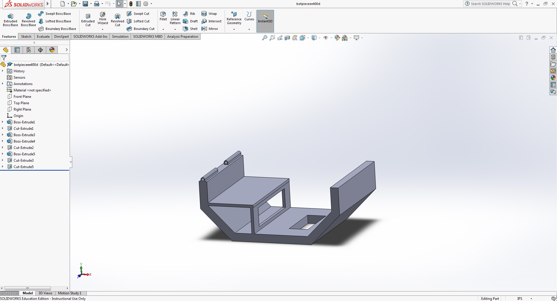
Figure 16 – Bottom piece of the center console.
The reason for this design is to add a base for the rear motors to sit on while also providing space underneath to fit any other electrical components we might have. For the hole at the bottom, we weren’t sure if we were going to continue the line following maze, so I created a hole at the bottom to accommodate for a line following sensor if needed. Also created a hinge like part to the rear of the bottom piece to connect with the top portion to mimic a closing feature.
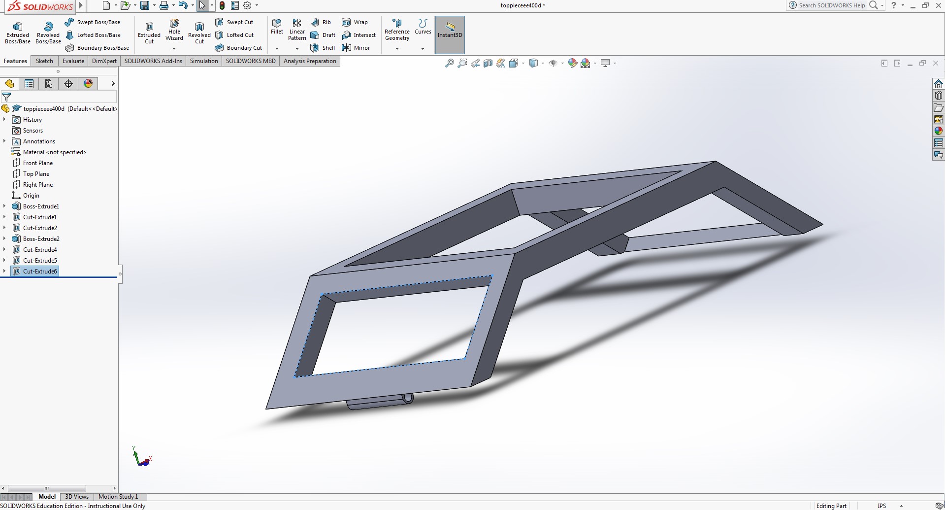
Figure 17 – Top piece of the center console.
Like the side pieces i wanted to keep the tank open until we figured out all the components in the tank. also added the connecting hinge to bottom portion of the tank.
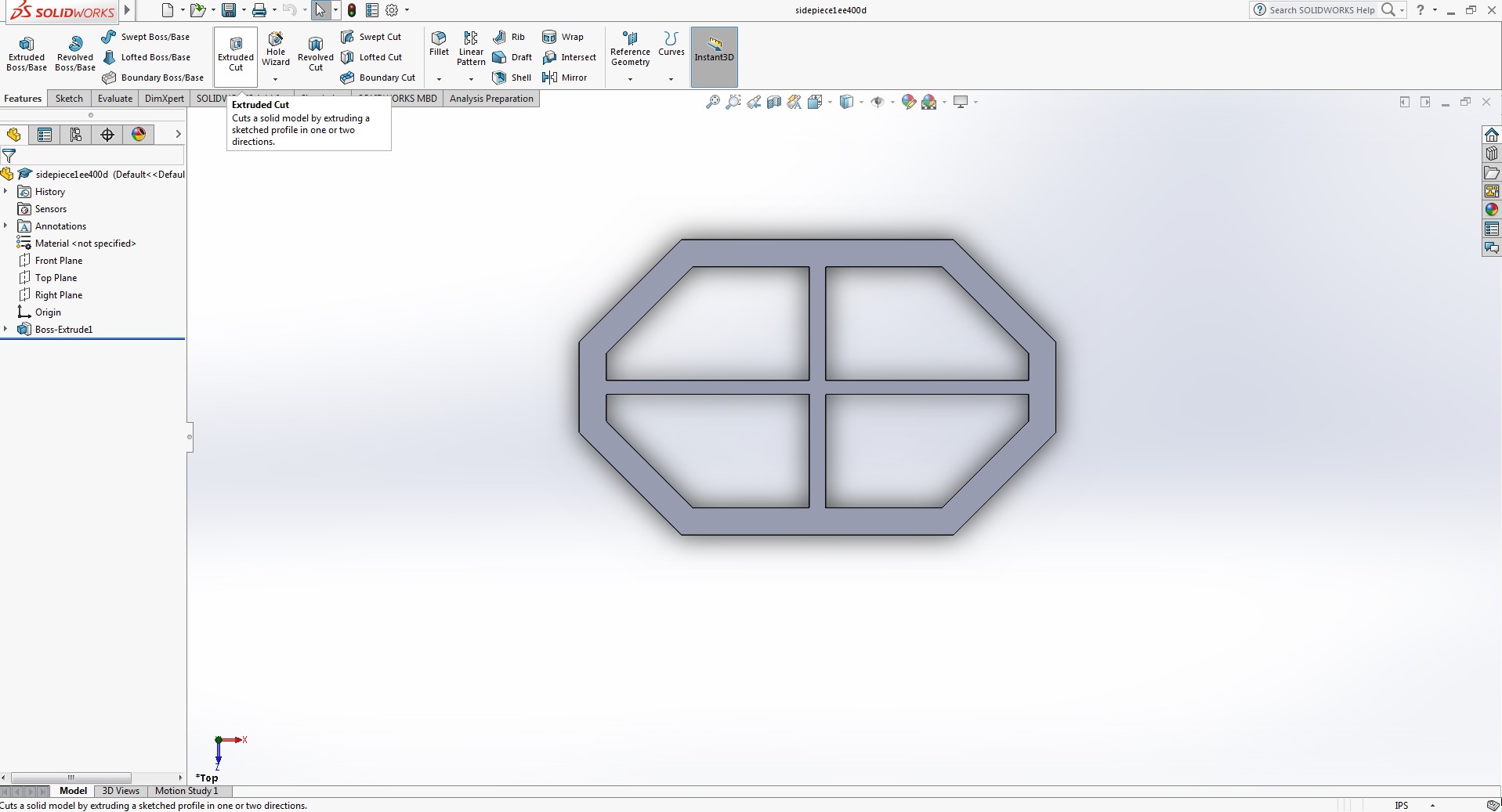
Figure 18 – Side piece for the Goliath.
Wanted to maintain an open design to freely move the parts where ever needed. Made the perimeter thicker than the previous model to be sturdier and be able to screw the pieces together if needed.
Resources
- www.arxterra.com/goliath-fall-2017-final-blog-post/
- www.arxterra.com/preliminary-design-document-2/
- http://web.csulb.edu/~hill/ee400d/Lectures/Week%2001%20Company%20and%20Mission/c_Job%20Descriptions.pdf
- https://docs.google.com/spreadsheets/d/19V-HOCEmgzXqFk2eOJVdiPhIjCBXNKYeMXI5y_aF87E/edit#gid=0
- Pro Micro
- I2C Expander
- https://www.arxterra.com/initial-design/
- https://docs.google.com/spreadsheets/d/15eEC1hPg-atkorm0VIFIhtkroHR1IgFu7A8-NwoKVB0/edit#gid=0
- https://docs.google.com/spreadsheets/d/1X2e8fMk9zH4d6ugtWx0KzsvcbpDvAjY_uL_h4tcDotE/edit
- https://www.projectlibre.com/
- ToF Range Finder
- https://docs.google.com/spreadsheets/d/1F9hwY03QBFUImZ_wKt4pEAWqgT7hq6SKrcHJS8AYq6I/edit#gid=1180904142


