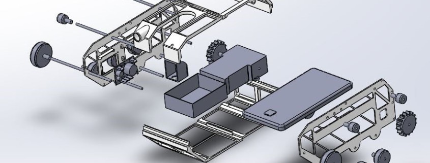
Category: 3DoT Goliath

  • MaxSonar Sensor Field of View Experiment

    MaxSonar Sensor Field of View Experiment

    [av_one_full first min_height=” vertical_alignment=” space=” custom_margin=” margin=’0px’ padding=’0px’ border=” border_color=” radius=’0px’ background_color=” src=” background_position=’top left’ background_repeat=’no-repeat’ animation=”]
    [av_textblock size=’25’ font_color=” color=”]
    Goliath Fall 2016
    [/av_textblock]

    [av_hr class=’invisible’ height=’-50′ shadow=’no-shadow’ position=’center’ custom_border=’av-border-thin’ custom_width=’50px’ custom_border_color=” custom_margin_top=’30px’ custom_margin_bottom=’30px’ icon_select=’yes’ custom_icon_color=” icon=’ue808′ font=’entypo-fontello’]

    [av_textblock size=’25’ font_color=” color=”]
    MaxSonar Sensor Field of View Experiment
    [/av_textblock]
    [/av_one_full]

    [av_hr class=’invisible’ height=’-60′ shadow=’no-shadow’ position=’center’ custom_border=’av-border-thin’ custom_width=’50px’ custom_border_color=” custom_margin_top=’30px’ custom_margin_bottom=’30px’ icon_select=’yes’ custom_icon_color=” icon=’ue808′ font=’entypo-fontello’]

    [av_textblock size=” font_color=’custom’ color=’#bfbfbf’]
    By: Sou Thao (Electronics and Control Engineer)

    Approved by Kristen Oduca (Project Manager)
    [/av_textblock]

    [av_three_fourth first min_height=” vertical_alignment=” space=” custom_margin=” margin=’0px’ padding=’0px’ border=” border_color=” radius=’0px’ background_color=” src=” background_position=’top left’ background_repeat=’no-repeat’ animation=”]
    [av_textblock size=’16’ font_color=’custom’ color=’#6b6b6b’]

    [/av_textblock]
    [/av_three_fourth]

    [av_one_full first min_height=” vertical_alignment=” space=” custom_margin=” margin=’0px’ padding=’0px’ border=” border_color=” radius=’0px’ background_color=” src=” background_position=’top left’ background_repeat=’no-repeat’ animation=”]

    [av_heading tag=’h2′ padding=’10’ heading=’Introduction’ color=’custom-color-heading’ style=” custom_font=’#ff6a00′ size=” subheading_active=” subheading_size=’15’ custom_class=”][/av_heading]

    [av_textblock size=” font_color=” color=”]
    Requirement: Goliath shall follow the Biped at a fixed distance of 20 inches with a margin of error of 15%.

    In order for Goliath to track the biped, we needed to understand its field of view of the sensors.  In other words, we want to know the viewing angle for each MaxSonar Sensor.  The sensors are the eyes of the rover, and by determining the viewing angle, we are able to get an ideal location of where BiPed can be placed so our sensors can see it.  
    [/av_textblock]

    [av_heading tag=’h2′ padding=’10’ heading=’Setting Up the MaxSonar Sensor’ color=’custom-color-heading’ style=” custom_font=’#ff6a00′ size=” subheading_active=” subheading_size=’15’ custom_class=”][/av_heading]

    [av_textblock size=” font_color=” color=”]
    Before setting up the experiment, we have to wire up and test our MaxSonar Sensor.  Because these sensors run on I2C, we connected the pinouts of the SCL and SDA from the MaxSonar Sensor to the Arduino Leonardo [1].  We also powered up the sensor with the 3.3V pin from the Leonardo, and grounded the last pin of the sensor.  After we wired up the sensor, we have to write a code using the Wire.h library in order to communicate with the device through I2C [2].  We first declare the address of the sensor and then begin the transmission to start ranging the sensor.  Then after the sensor begins to operate, we write the information that the sensor is sending back to the variable SensorDistance.  The sensors sends back two bytes of data because it can detect distances up to 25 feet.  However, we can discard the higher byte because we do not need the bigger distances. This is displayed in our Fritzing and Breadboard photo shown in Figures 1 and 2.
    [/av_textblock]

    [av_hr class=’invisible’ height=’20’ shadow=’no-shadow’ position=’center’ custom_border=’av-border-thin’ custom_width=’50px’ custom_border_color=” custom_margin_top=’30px’ custom_margin_bottom=’30px’ icon_select=’yes’ custom_icon_color=” icon=’ue808′ font=’entypo-fontello’]

    [av_textblock size=” font_color=” color=”]

    Figure 1 - Fritzing Diagram
    Figure 1 – Fritzing Diagram

    [/av_textblock]

    [av_hr class=’invisible’ height=’20’ shadow=’no-shadow’ position=’center’ custom_border=’av-border-thin’ custom_width=’50px’ custom_border_color=” custom_margin_top=’30px’ custom_margin_bottom=’30px’ icon_select=’yes’ custom_icon_color=” icon=’ue808′ font=’entypo-fontello’]

    [av_textblock size=” font_color=” color=”]

    Figure 2 - Bread Board Photo
    Figure 2 – Bread Board Photo

    [/av_textblock]

    [av_hr class=’invisible’ height=’20’ shadow=’no-shadow’ position=’center’ custom_border=’av-border-thin’ custom_width=’50px’ custom_border_color=” custom_margin_top=’30px’ custom_margin_bottom=’30px’ icon_select=’yes’ custom_icon_color=” icon=’ue808′ font=’entypo-fontello’]

    [av_textblock size=” font_color=” color=”]
    Thus our code is:
    [/av_textblock]

    [av_hr class=’invisible’ height=’20’ shadow=’no-shadow’ position=’center’ custom_border=’av-border-thin’ custom_width=’50px’ custom_border_color=” custom_margin_top=’30px’ custom_margin_bottom=’30px’ icon_select=’yes’ custom_icon_color=” icon=’ue808′ font=’entypo-fontello’]

    [av_textblock size=” font_color=” color=”]
    #define Address 0x71

    #include

    byte rangeCommand = 0x51;

    int SensorDistance,discard;

    void setup() {

    Wire.begin();

    Serial1.begin(9600);

    }

    void loop() {

    Wire.beginTransmission(Address);

    Wire.write(rangeCommand);

    Wire.requestFrom(Address,2);

    while(!Wire.available()){}

    discard1=Wire.read();

    SensorDistance=Wire.read();

    Serial.println(SensorDistance);

    Wire.endTransmission();

    delay(60);

    }
    [/av_textblock]

    [av_hr class=’invisible’ height=’20’ shadow=’no-shadow’ position=’center’ custom_border=’av-border-thin’ custom_width=’50px’ custom_border_color=” custom_margin_top=’30px’ custom_margin_bottom=’30px’ icon_select=’yes’ custom_icon_color=” icon=’ue808′ font=’entypo-fontello’]

    [av_textblock size=” font_color=’custom’ color=’#ff6a00′]
    Source Material

    1. http://www.maxbotix.com/documents/I2CXL-MaxSonar-EZ_Datasheet.pdf
    2. http://playground.arduino.cc/Main/WireLibraryDetailedReference

    [/av_textblock]

    [av_heading tag=’h2′ padding=’10’ heading=’Experiment’ color=’custom-color-heading’ style=” custom_font=’#ff6a00′ size=” subheading_active=” subheading_size=’15’ custom_class=”][/av_heading]

    [av_textblock size=” font_color=” color=”]
    For setting up the experiment, we took 9 pieces of paper and taped them together.  Next we put the sensor at one end of the paper and took an object and moved it across the paper.  For the object, we used a caliper which was thin enough to represent a small object.  As we moved the caliper across the paper, we made marks of where the sensor was able to detect the caliper.  We also marked points right where the sensor was not able to detect the object.  From this, we drew an area with a green marker, which represents ideally where an object can be for the sensor to detect it.  This is shown in Figures 3 and 4.
    [/av_textblock]

    [av_hr class=’invisible’ height=’20’ shadow=’no-shadow’ position=’center’ custom_border=’av-border-thin’ custom_width=’50px’ custom_border_color=” custom_margin_top=’30px’ custom_margin_bottom=’30px’ icon_select=’yes’ custom_icon_color=” icon=’ue808′ font=’entypo-fontello’]

    [av_textblock size=” font_color=” color=”]

    Figure 3 - Pieces of Paper Taped Together
    Figure 3 – Pieces of Paper Taped Together

    [/av_textblock]

    [av_hr class=’invisible’ height=’20’ shadow=’no-shadow’ position=’center’ custom_border=’av-border-thin’ custom_width=’50px’ custom_border_color=” custom_margin_top=’30px’ custom_margin_bottom=’30px’ icon_select=’yes’ custom_icon_color=” icon=’ue808′ font=’entypo-fontello’]

    [av_textblock size=” font_color=” color=”]

    Figure 4 - Placing Object for Sensor to Detect
    Figure 4 – Placing Object for Sensor to Detect

    [/av_textblock]

    [av_hr class=’invisible’ height=’20’ shadow=’no-shadow’ position=’center’ custom_border=’av-border-thin’ custom_width=’50px’ custom_border_color=” custom_margin_top=’30px’ custom_margin_bottom=’30px’ icon_select=’yes’ custom_icon_color=” icon=’ue808′ font=’entypo-fontello’]

    [av_textblock size=” font_color=” color=”]
    After mapping out the areas of where the sensor can detect objects, we next drew a triangle using a black marker on the paper to where it would be best to put an object.  By doing this, we can find the viewing angle of the sensor.  The angle θ in the picture is the angle we want to find.  By drawing a line out 30 inches from the sensor to the end of the paper, we measured the distance across the 30 inches line which came out to be 15inches.  Next we measured the side lengths of the triangle and found the distances to be near 30inches.  Because we have the lengths of each side of the triangle, we used one of the geometry rules to determine the angle which came out to be about 30 degrees. The final results are shown in Figure 5.
    [/av_textblock]

    [av_hr class=’invisible’ height=’20’ shadow=’no-shadow’ position=’center’ custom_border=’av-border-thin’ custom_width=’50px’ custom_border_color=” custom_margin_top=’30px’ custom_margin_bottom=’30px’ icon_select=’yes’ custom_icon_color=” icon=’ue808′ font=’entypo-fontello’]

    [av_textblock size=” font_color=” color=”]

    Figure 5 - Final Results
    Figure 5 – Final Results

    [/av_textblock]

    [av_heading tag=’h2′ padding=’10’ heading=’Conclusion’ color=’custom-color-heading’ style=” custom_font=’#ff6a00′ size=” subheading_active=” subheading_size=’15’ custom_class=”][/av_heading]

    [av_textblock size=” font_color=” color=”]
    By conducting this experiment, we were able to determine the viewing angle of our sensor.  The viewing angle is about 30 degrees, meaning that the sensor can detect any object within its 30 degrees field of view.  Thus, we can adjust the sensors and place it at different locations on our Goliath to detect other objects.  Also, from the field of view, we will be able to determine the amount of distance to separate the two sensors and code them to automate the movement of our Goliath based on the tracked object.
    [/av_textblock]

    [/av_one_full]

  • Motor Trade Off Study

    Motor Trade Off Study

    [av_one_full first min_height=” vertical_alignment=” space=” custom_margin=” margin=’0px’ padding=’0px’ border=” border_color=” radius=’0px’ background_color=” src=” background_position=’top left’ background_repeat=’no-repeat’ animation=”]
    [av_textblock size=’25’ font_color=” color=”]
    Goliath Fall 2016
    [/av_textblock]

    [av_hr class=’invisible’ height=’-50′ shadow=’no-shadow’ position=’center’ custom_border=’av-border-thin’ custom_width=’50px’ custom_border_color=” custom_margin_top=’30px’ custom_margin_bottom=’30px’ icon_select=’yes’ custom_icon_color=” icon=’ue808′ font=’entypo-fontello’]

    [av_textblock size=’25’ font_color=” color=”]
    Motor Trade Off Study
    [/av_textblock]
    [/av_one_full]

    [av_hr class=’invisible’ height=’-60′ shadow=’no-shadow’ position=’center’ custom_border=’av-border-thin’ custom_width=’50px’ custom_border_color=” custom_margin_top=’30px’ custom_margin_bottom=’30px’ icon_select=’yes’ custom_icon_color=” icon=’ue808′ font=’entypo-fontello’]

    [av_textblock size=” font_color=’custom’ color=’#bfbfbf’]
    By: Sou Thao (Electronics and Control Engineer)

    Approved by Kristen Oduca (Project Manager)
    [/av_textblock]

    [av_three_fourth first min_height=” vertical_alignment=” space=” custom_margin=” margin=’0px’ padding=’0px’ border=” border_color=” radius=’0px’ background_color=” src=” background_position=’top left’ background_repeat=’no-repeat’ animation=”]
    [av_textblock size=’16’ font_color=’custom’ color=’#6b6b6b’]

    [/av_textblock]
    [/av_three_fourth]

    [av_one_full first min_height=” vertical_alignment=” space=” custom_margin=” margin=’0px’ padding=’0px’ border=” border_color=” radius=’0px’ background_color=” src=” background_position=’top left’ background_repeat=’no-repeat’ animation=”]

    [av_heading tag=’h2′ padding=’10’ heading=’Introduction ‘ color=’custom-color-heading’ style=” custom_font=’#ff6a00′ size=” subheading_active=” subheading_size=’15’ custom_class=”][/av_heading]

    [av_textblock size=” font_color=” color=”]
    In order to carry a weight of 281 grams, as determined in the mass report [1], and to make Goliath as small as humanly possible due to the printing time requirement, Goliath will need a motor that can fit the chassis with a torque of at least 9.15oz*in.  This torque was calculated from an experiment conducted with the previous Goliath, which gave us an idea of an estimated torque necessary to drive tracked vehicles.  Given the torque, this motor trade off study consisted of researching different motors that can meet these specifications.
    [/av_textblock]

    [av_heading tag=’h2′ padding=’10’ heading=’Motor Specifications’ color=’custom-color-heading’ style=” custom_font=’#ff6a00′ size=” subheading_active=” subheading_size=’15’ custom_class=”][/av_heading]

    [av_textblock size=” font_color=” color=”]
    Tamiya 70168 Double Gearbox Motor

    • Operating Voltage: 3V
    • Gear Ratio Options: 12.7, 38, 115, 344:1
    • Free-run motor shaft speed at 3V: 12300rpm
    • Free-run current at 3V: 150mA
    • Stall current at 3V: 2100mA
    • Motor shaft stall torque at 3V: 0.5oz*in

    [/av_textblock]

    [av_hr class=’invisible’ height=’20’ shadow=’no-shadow’ position=’center’ custom_border=’av-border-thin’ custom_width=’50px’ custom_border_color=” custom_margin_top=’30px’ custom_margin_bottom=’30px’ icon_select=’yes’ custom_icon_color=” icon=’ue808′ font=’entypo-fontello’]

    [av_textblock size=” font_color=” color=”]
    Solarbotics GM6 Mini Gear Motor

    • Gear ratio: 120:1
    • Free-run speed at 6V: 157rpm
    • Free-run current at 6V: 97mA
    • Stall current at 6V: 563mA
    • Stall torque at 6V: 21oz*in
    • Free-run speed at 3V: 64rpm
    • Free-run current at 3V: 64mA
    • Stall current at 3V: 326mA
    • Stall torque at 3V: 140z*in
    • Size: 36.5×27.5x25mm

    [/av_textblock]

    [av_hr class=’invisible’ height=’20’ shadow=’no-shadow’ position=’center’ custom_border=’av-border-thin’ custom_width=’50px’ custom_border_color=” custom_margin_top=’30px’ custom_margin_bottom=’30px’ icon_select=’yes’ custom_icon_color=” icon=’ue808′ font=’entypo-fontello’]

    [av_textblock size=” font_color=” color=”]
    Polulu Micro Metal Gearmotor

    • Gear ratio: 150.58:1
    • Free-run speed at 6V: 150rpm
    • Free-run current at 6V: 40mA
    • Stall current at 6V: 700mA
    • Stall torque at 6V: 28oz*in
    • Size: 10x12x26mm

    [/av_textblock]

    [av_heading tag=’h2′ padding=’10’ heading=’Analysis of Motors’ color=’custom-color-heading’ style=” custom_font=’#ff6a00′ size=” subheading_active=” subheading_size=’15’ custom_class=”][/av_heading]

    [av_textblock size=” font_color=” color=”]
    Torque is important when considering DC motors.  For robot applications, the gear motors have an added gear-down to reduce speed and increase torque.  There are many applications for having more speed than torque and vice versa, such as race cars needing more speed to go fast or a truck that needs more torque to move heavier loads.  Based on the Goliath, there needs to be a balance in torque and speed so it can go up an incline and stay within a distance from the BiPed.  By looking at the specs of a DC motor, we can use the rated shaft speed, rated torque, and the gear ratios to select the best motor for our Goliath.  First, to determine the speed, we can divide the rated shaft speed by the gear ratio.  Next, to determine the torque, we can multiply the torque rating by the gear ratio. Thus, we can adjust the gear ratio or buy a motor with similar configurations to make our motor fast and powerful.
    [/av_textblock]

    [av_hr class=’invisible’ height=’20’ shadow=’no-shadow’ position=’center’ custom_border=’av-border-thin’ custom_width=’50px’ custom_border_color=” custom_margin_top=’30px’ custom_margin_bottom=’30px’ icon_select=’yes’ custom_icon_color=” icon=’ue808′ font=’entypo-fontello’]

    [av_textblock size=” font_color=” color=”]
    The plastic gearbox motors such as the GM6 had a motor stall torque of 21oz.*in. and dimension of 36.5×27.5×25 mm. This motor is good for its size, however, because we want to make our Goliath as small as humanly possible, we had to research other smaller motors.
    [/av_textblock]

    [av_hr class=’invisible’ height=’20’ shadow=’no-shadow’ position=’center’ custom_border=’av-border-thin’ custom_width=’50px’ custom_border_color=” custom_margin_top=’30px’ custom_margin_bottom=’30px’ icon_select=’yes’ custom_icon_color=” icon=’ue808′ font=’entypo-fontello’]

    [av_textblock size=” font_color=” color=”]
    The micro metal gearmotors were ideal for our application. Their size are 10x12x26 mm and they come in different sizes that can give us the necessary torque to drive our Goliath. Because they are made up of metal, these motors are more powerful than the plastic gearbox motors and they can drive more torque. For our purpose, we should choose a micro metal gearbox motor with a torque higher than 9.15oz*in.
    [/av_textblock]

    [av_heading tag=’h2′ padding=’10’ heading=’Conclusion’ color=’custom-color-heading’ style=” custom_font=’#ff6a00′ size=” subheading_active=” subheading_size=’15’ custom_class=”][/av_heading]

    [av_textblock size=” font_color=” color=”]
    From the motor trade off study, three different motors were compared and the best motor out of all three of them were the Polulu micro metal gear motors. They are relatively small, but are powerful enough to provide us with the amount of speed and torque needed for drive our application. Because our printing time requirement is at most 6 hours, our chassis will need to be small. Thus, the micro metal gear motors size of 10x12x26 mm will be able to fit within our chassis.
    [/av_textblock]

    [av_hr class=’invisible’ height=’20’ shadow=’no-shadow’ position=’center’ custom_border=’av-border-thin’ custom_width=’50px’ custom_border_color=” custom_margin_top=’30px’ custom_margin_bottom=’30px’ icon_select=’yes’ custom_icon_color=” icon=’ue808′ font=’entypo-fontello’]

    [av_textblock size=” font_color=’custom’ color=’#ff6a00′]
    Source Material

    1. http://arxterra.com/goliath-fall-2016-preliminary-project-plan/
    2. https://www.pololu.com/product/114/pictures
    3. https://www.pololu.com/category/60/micro-metal-gearmotors
    4. https://www.pololu.com/product/182
    5. http://www.robotshop.com/blog/en/how-do-i-interpret-dc-motor-specifications-3657
    6. https://www.intorobotics.com/2-simple-methods-choose-motors-wheel-drive-robots/
    7. http://www.robotshop.com/blog/en/drive-motor-sizing-tool-9698

    [/av_textblock]

    [/av_one_full]

  • Experiment to Determine Torque to Weight Ratio

    Experiment to Determine Torque to Weight Ratio

    [av_one_full first min_height=” vertical_alignment=” space=” custom_margin=” margin=’0px’ padding=’0px’ border=” border_color=” radius=’0px’ background_color=” src=” background_position=’top left’ background_repeat=’no-repeat’ animation=”]
    [av_textblock size=’25’ font_color=” color=”]
    Goliath Fall 2016
    [/av_textblock]

    [av_hr class=’invisible’ height=’-50′ shadow=’no-shadow’ position=’center’ custom_border=’av-border-thin’ custom_width=’50px’ custom_border_color=” custom_margin_top=’30px’ custom_margin_bottom=’30px’ icon_select=’yes’ custom_icon_color=” icon=’ue808′ font=’entypo-fontello’]

    [av_textblock size=’25’ font_color=” color=”]
    Experiment to Determine Torque to Weight Ratio
    [/av_textblock]
    [/av_one_full]

    [av_hr class=’invisible’ height=’-60′ shadow=’no-shadow’ position=’center’ custom_border=’av-border-thin’ custom_width=’50px’ custom_border_color=” custom_margin_top=’30px’ custom_margin_bottom=’30px’ icon_select=’yes’ custom_icon_color=” icon=’ue808′ font=’entypo-fontello’]

    [av_textblock size=” font_color=’custom’ color=’#bfbfbf’]
    By: Sou Thao (Electronics and Control Engineer)

    Approved by Kristen Oduca (Project Manager)
    [/av_textblock]

    [av_one_full first min_height=” vertical_alignment=” space=” custom_margin=” margin=’0px’ padding=’0px’ border=” border_color=” radius=’0px’ background_color=” src=” background_position=’top left’ background_repeat=’no-repeat’ animation=”]

    [av_heading tag=’h2′ padding=’10’ heading=’Introduction’ color=’custom-color-heading’ style=” custom_font=’#ff6a00′ size=” subheading_active=” subheading_size=’15’ custom_class=”][/av_heading]

    [av_textblock size=” font_color=” color=”]
    In order to select the correct motor torque to use, an experiment was performed with the previous Goliath to determine the torque to weight ratio for tracked vehicles. From this ratio, we will be able to get an estimate of the amount of torque necessary to drive our new Goliath tank.  In order to conduct this experiment we used the following items: the previous semester’s Goliath tank, a weight scale, a breadboard, and an Arduino Leonardo connected with a L293D Motor Driver.
    [/av_textblock]

    [av_heading tag=’h2′ padding=’10’ heading=’Experiment ‘ color=’custom-color-heading’ style=” custom_font=’#ff6a00′ size=” subheading_active=” subheading_size=’15’ custom_class=”][/av_heading]

    [av_textblock size=” font_color=” color=”]
    The pin input from the motor driver was connected to the Leonardo digital pins and its output was connected to the motors. This is shown in the Fritzing Diagram in Figure 1.
    [/av_textblock]

    [av_hr class=’invisible’ height=’20’ shadow=’no-shadow’ position=’center’ custom_border=’av-border-thin’ custom_width=’50px’ custom_border_color=” custom_margin_top=’30px’ custom_margin_bottom=’30px’ icon_select=’yes’ custom_icon_color=” icon=’ue808′ font=’entypo-fontello’]

    [av_textblock size=” font_color=” color=”]

    Figure 1 - Fritzing Diagram
    Figure 1 – Fritzing Diagram

    [/av_textblock]

    [av_hr class=’invisible’ height=’20’ shadow=’no-shadow’ position=’center’ custom_border=’av-border-thin’ custom_width=’50px’ custom_border_color=” custom_margin_top=’30px’ custom_margin_bottom=’30px’ icon_select=’yes’ custom_icon_color=” icon=’ue808′ font=’entypo-fontello’]

    [av_textblock size=” font_color=” color=”]
    A simple code was created to allow the Goliath to move forward.  After this, a measurement of its weight was taken to determine the amount of torque being outputted from each wheels.  The weight of the Goliath with the battery pack, a breadboard, and the Leonardo came out to be 442g as shown in Figure 2.
    [/av_textblock]

    [av_hr class=’invisible’ height=’20’ shadow=’no-shadow’ position=’center’ custom_border=’av-border-thin’ custom_width=’50px’ custom_border_color=” custom_margin_top=’30px’ custom_margin_bottom=’30px’ icon_select=’yes’ custom_icon_color=” icon=’ue808′ font=’entypo-fontello’]

    [av_textblock size=” font_color=” color=”]

    Figure 2 - Spring 2016 Goliath Weight
    Figure 2 – Spring 2016 Goliath Weight

    [/av_textblock]

    [av_hr class=’invisible’ height=’20’ shadow=’no-shadow’ position=’center’ custom_border=’av-border-thin’ custom_width=’50px’ custom_border_color=” custom_margin_top=’30px’ custom_margin_bottom=’30px’ icon_select=’yes’ custom_icon_color=” icon=’ue808′ font=’entypo-fontello’]

    [av_textblock size=” font_color=” color=”]
    Next, we measured the time it took for Goliath to travel a distance of 3ft to determine its velocity as shown in Figure 3.  
    [/av_textblock]

    [av_hr class=’invisible’ height=’20’ shadow=’no-shadow’ position=’center’ custom_border=’av-border-thin’ custom_width=’50px’ custom_border_color=” custom_margin_top=’30px’ custom_margin_bottom=’30px’ icon_select=’yes’ custom_icon_color=” icon=’ue808′ font=’entypo-fontello’]

    [av_textblock size=” font_color=” color=”]

    Figure 3 - Measuring Spring 2016 Velocity
    Figure 3 – Measuring Spring 2016 Velocity

    [/av_textblock]

    [av_hr class=’invisible’ height=’20’ shadow=’no-shadow’ position=’center’ custom_border=’av-border-thin’ custom_width=’50px’ custom_border_color=” custom_margin_top=’30px’ custom_margin_bottom=’30px’ icon_select=’yes’ custom_icon_color=” icon=’ue808′ font=’entypo-fontello’]

    [av_textblock size=” font_color=” color=”]
    To calculate the torque, we also need the force acting on each wheel and the radius of the wheel.  The force acting on the wheel is gravity, and the radius of the wheel is about 20mm or 0.02m.  Thus, we used different equations to find our torque as shown in Figure 4:
    [/av_textblock]

    [av_hr class=’invisible’ height=’20’ shadow=’no-shadow’ position=’center’ custom_border=’av-border-thin’ custom_width=’50px’ custom_border_color=” custom_margin_top=’30px’ custom_margin_bottom=’30px’ icon_select=’yes’ custom_icon_color=” icon=’ue808′ font=’entypo-fontello’]

    [av_textblock size=” font_color=” color=”]

    Figure - 4 Torque Calculations
    Figure – 4 Torque Calculations

    [/av_textblock]

    [av_hr class=’invisible’ height=’20’ shadow=’no-shadow’ position=’center’ custom_border=’av-border-thin’ custom_width=’50px’ custom_border_color=” custom_margin_top=’30px’ custom_margin_bottom=’30px’ icon_select=’yes’ custom_icon_color=” icon=’ue808′ font=’entypo-fontello’]

    [av_textblock size=” font_color=” color=”]
    Now that the torque was determined from the previous Goliath, we can get a torque to weight ratio and determine the amount of torque needed to drive our new Goliath.  By dividing the torque by the weight of the previous Goliath, we get 0.0278oz*in/g.  This torque ratio can be applied to tracked vehicles, thus, we can get an estimate of the torque we need.  Because the estimated weight of the new Goliath is 329g, we multiply this weight by the torque to weight ratio to get our needed torque, which is 9.15oz*in.
    [/av_textblock]

    [av_heading tag=’h2′ padding=’10’ heading=’Conclusion’ color=’custom-color-heading’ style=” custom_font=’#ff6a00′ size=” subheading_active=” subheading_size=’15’ custom_class=”][/av_heading]

    [av_textblock size=” font_color=” color=”]
    The minimum size torque we should look for when selecting a motor is 9.15oz*in.  We conducted this experiment to determine the torque to weight ratio of the previous Goliath to give us an ideal torque to use for our application.  Because Goliath is a tracked vehicle, we could not theoretically calculate the torque in the limited amount of time given because there are many forces acting on the Goliath such as tractive and friction forces.  Therefore, by running a test on the previous Goliath, we were able to quickly get a ideal torque so we can select our motors.
    [/av_textblock]

    [av_hr class=’invisible’ height=’20’ shadow=’no-shadow’ position=’center’ custom_border=’av-border-thin’ custom_width=’50px’ custom_border_color=” custom_margin_top=’30px’ custom_margin_bottom=’30px’ icon_select=’yes’ custom_icon_color=” icon=’ue808′ font=’entypo-fontello’]

    [av_textblock size=” font_color=’custom’ color=’#ff6a00′]
    Source Material

    1. https://www.physicsforums.com/threads/calculate-wheel-torque-based-on-known-weight-wheel-size-acceleration-data.288570/
    2. http://physics.stackexchange.com/questions/52306/calculation-of-torque-for-motor-used-in-4-wheel-robot
    3. https://www.physicsforums.com/threads/torque-on-a-wheel.779906/

    [/av_textblock]

    [/av_one_full]

  • Tracking Sensors Trade Off Study

    Tracking Sensors Trade Off Study

    [av_one_full first min_height=” vertical_alignment=” space=” custom_margin=” margin=’0px’ padding=’0px’ border=” border_color=” radius=’0px’ background_color=” src=” background_position=’top left’ background_repeat=’no-repeat’ animation=”]
    [av_textblock size=’25’ font_color=” color=”]
    Goliath Fall 2016
    [/av_textblock]

    [av_hr class=’invisible’ height=’-50′ shadow=’no-shadow’ position=’center’ custom_border=’av-border-thin’ custom_width=’50px’ custom_border_color=” custom_margin_top=’30px’ custom_margin_bottom=’30px’ icon_select=’yes’ custom_icon_color=” icon=’ue808′ font=’entypo-fontello’]

    [av_textblock size=’25’ font_color=” color=”]
    Tracking Sensors Trade Off Study
    [/av_textblock]
    [/av_one_full]

    [av_hr class=’invisible’ height=’-60′ shadow=’no-shadow’ position=’center’ custom_border=’av-border-thin’ custom_width=’50px’ custom_border_color=” custom_margin_top=’30px’ custom_margin_bottom=’30px’ icon_select=’yes’ custom_icon_color=” icon=’ue808′ font=’entypo-fontello’]

    [av_textblock size=” font_color=’custom’ color=’#bfbfbf’]
    By: Sou Thao (Electronics and Control Engineer)

    Approved by Kristen Oduca (Project Manager)
    [/av_textblock]

    [av_three_fourth first min_height=” vertical_alignment=” space=” custom_margin=” margin=’0px’ padding=’0px’ border=” border_color=” radius=’0px’ background_color=” src=” background_position=’top left’ background_repeat=’no-repeat’ animation=”]
    [av_textblock size=’16’ font_color=’custom’ color=’#6b6b6b’]

    [/av_textblock]
    [/av_three_fourth]

    [av_one_full first min_height=” vertical_alignment=” space=” custom_margin=” margin=’0px’ padding=’0px’ border=” border_color=” radius=’0px’ background_color=” src=” background_position=’top left’ background_repeat=’no-repeat’ animation=”]

    [av_heading tag=’h2′ padding=’10’ heading=’Introduction’ color=’custom-color-heading’ style=” custom_font=’#ff6a00′ size=” subheading_active=” subheading_size=’15’ custom_class=” admin_preview_bg=” av-desktop-hide=” av-medium-hide=” av-small-hide=” av-mini-hide=” av-medium-font-size-title=” av-small-font-size-title=” av-mini-font-size-title=” av-medium-font-size=” av-small-font-size=” av-mini-font-size=”][/av_heading]

    [av_textblock size=” font_color=” color=”]
    In order to achieve the mission profile of being autonomous [1] and to fulfill the level 2 requirement of following BiPed at a fixed distance of 20 inches [1], Goliath must use sensors.  However, the 20 inches is just an estimate used. There still needs to be valid calculations for this requirement. This trade off study was performed to determine the minimum amount of sensors needed for Goliath to be autonomous, and to determine the best sensors to use for tracking an object.  
    [/av_textblock]

    [av_heading tag=’h2′ padding=’10’ heading=’Amount of Sensors Needed ‘ color=’custom-color-heading’ style=” custom_font=’#ff6a00′ size=” subheading_active=” subheading_size=’15’ custom_class=” admin_preview_bg=” av-desktop-hide=” av-medium-hide=” av-small-hide=” av-mini-hide=” av-medium-font-size-title=” av-small-font-size-title=” av-mini-font-size-title=” av-medium-font-size=” av-small-font-size=” av-mini-font-size=”][/av_heading]

    [av_textblock size=” font_color=” color=”]
    From the research performed, the minimum amount of sensors required to make a robot autonomous is two sensors.  If only one sensor is used, the robot will only be able to detect objects in a one directional plane.  This will translate to movements of going forward and backward.  By having two sensors, the robot will be able to have a two directional plane of view where it can go forward, backward, turn left, and turn right.  When the two sensors are in use, there will be five scenarios that it will face in order to stimulate the movement of the robot as shown in the following list:

    1. If the sensors are too far from an object, the robot will move forward.
    2. If the sensors are too close to an object, the robot will move backwards.
    3. If the sensors are within the range of an object, the robot will not move.
    4. If the left sensor’s distance is less than the right sensor’s distance, the robot will turn left.
    5. If the right sensor’s distance is less than the left sensor’s distance, the robot will turn right.

    [/av_textblock]

    [av_heading tag=’h2′ padding=’10’ heading=’Types of Sensors’ color=’custom-color-heading’ style=” custom_font=’#ff6a00′ size=” subheading_active=” subheading_size=’15’ custom_class=” admin_preview_bg=” av-desktop-hide=” av-medium-hide=” av-small-hide=” av-mini-hide=” av-medium-font-size-title=” av-small-font-size-title=” av-mini-font-size-title=” av-medium-font-size=” av-small-font-size=” av-mini-font-size=”][/av_heading]

    [av_textblock size=” font_color=” color=”]
    By looking through different types of follower robots, the most commonly used sensors were:

    • Ultrasonic Sensors mainly HC-SR04 shown in Figure 1 

    [/av_textblock]

    [av_hr class=’invisible’ height=’20’ shadow=’no-shadow’ position=’center’ custom_border=’av-border-thin’ custom_width=’50px’ custom_border_color=” custom_margin_top=’30px’ custom_margin_bottom=’30px’ icon_select=’yes’ custom_icon_color=” icon=’ue808′ font=’entypo-fontello’]

    [av_textblock size=” font_color=” color=”]

    Figure 1 - Ultrasonic Sensors
    Figure 1 – Ultrasonic Sensors

    [/av_textblock]

    [av_hr class=’invisible’ height=’20’ shadow=’no-shadow’ position=’center’ custom_border=’av-border-thin’ custom_width=’50px’ custom_border_color=” custom_margin_top=’30px’ custom_margin_bottom=’30px’ icon_select=’yes’ custom_icon_color=” icon=’ue808′ font=’entypo-fontello’]

    [av_textblock size=” font_color=” color=”]

    •  Sharp Distance Sensors shown in Figure 2

    [/av_textblock]

    [av_hr class=’invisible’ height=’20’ shadow=’no-shadow’ position=’center’ custom_border=’av-border-thin’ custom_width=’50px’ custom_border_color=” custom_margin_top=’30px’ custom_margin_bottom=’30px’ icon_select=’yes’ custom_icon_color=” icon=’ue808′ font=’entypo-fontello’]

    [av_textblock size=” font_color=” color=”]

    Figure 2 - Sharp Distance Sensors
    Figure 2 – Sharp Distance Sensors

    [/av_textblock]

    [av_hr class=’invisible’ height=’20’ shadow=’no-shadow’ position=’center’ custom_border=’av-border-thin’ custom_width=’50px’ custom_border_color=” custom_margin_top=’30px’ custom_margin_bottom=’30px’ icon_select=’yes’ custom_icon_color=” icon=’ue808′ font=’entypo-fontello’]

    [av_textblock size=” font_color=” color=”]

    •  Sharp Distance Sensors shown in Figure 3 [2]
      • Geetech IR Proximity Switch Module
      • Gravity Adjustable Infrared Sensor Switch

    [/av_textblock]

    [av_hr class=’invisible’ height=’20’ shadow=’no-shadow’ position=’center’ custom_border=’av-border-thin’ custom_width=’50px’ custom_border_color=” custom_margin_top=’30px’ custom_margin_bottom=’30px’ icon_select=’yes’ custom_icon_color=” icon=’ue808′ font=’entypo-fontello’]

    [av_textblock size=” font_color=” color=”]

    Figure 3 - IR Sensor Switch
    Figure 3 – IR Sensor Switch

    [/av_textblock]

    [av_heading tag=’h2′ padding=’10’ heading=’Sensors Pros and Cons’ color=’custom-color-heading’ style=” custom_font=’#ff6a00′ size=” subheading_active=” subheading_size=’15’ custom_class=” admin_preview_bg=” av-desktop-hide=” av-medium-hide=” av-small-hide=” av-mini-hide=” av-medium-font-size-title=” av-small-font-size-title=” av-mini-font-size-title=” av-medium-font-size=” av-small-font-size=” av-mini-font-size=”][/av_heading]

    [av_textblock size=” font_color=” color=”]
    Ultrasonic sensors have a range of 2-450cm (0.78-177in) which will be suitable to track the BiPed from 20 inches away.  The way ultrasonic sensors operate is through emitting sound waves and detecting the sound reflected back from the object.  From the reflected sound, the sensor can provide a measurement of how far an object is away from it.  The pros of ultrasonic sensors are that they can detect objects from farther distances and they can detect small objects accurately.  Also they can operate in harsh conditions such as dirt.  However, they have slower response times than other sensors, their measurements can be distorted by loud noises, and surfaces that absorb sound can deter their measurements.  The dual cylinder HC-SR04 is powered up through a 5V source, which will not be suitable for our application because we are using a 3.3V source coming through the I2C pins of the 3DoT board.  However, the single cylinder MaxSonar EZ1 Sensor can be powered through a 3V source, and it is compatible with the I2C.  Because it only has a single cylinder, it takes up less space than the regular HC-SR04.  This makes the MaxSonar EZ1 Sensor the ideal sensor to use in our application.
    [/av_textblock]

    [av_hr class=’invisible’ height=’20’ shadow=’no-shadow’ position=’center’ custom_border=’av-border-thin’ custom_width=’50px’ custom_border_color=” custom_margin_top=’30px’ custom_margin_bottom=’30px’ icon_select=’yes’ custom_icon_color=” icon=’ue808′ font=’entypo-fontello’]

    [av_textblock size=” font_color=” color=”]
    Sharp distance sensors have a range of 10-150cm (3.93-59.1in) which are suitable to track the BiPed from 20 inches away.  They are designed using an IR emitter and receiver, and they work by sending out IR signals and detecting the reflected infrared light.  These sensors have special lenses incorporated into the LEDs so that they can emit and detect signals from a farther distance.  They are inexpensive and perform better than other IR Sensors due to the shaping of the lenses.  However, the sun or any object that emits IR signals can deter its measurements.  Also, the color of the tracked object will affect the measurements because some color absorb or reflect light better than others.  These sensors run on 3V, however, because IR sensors are affected by the light from the sun and other light sources, these sensors are not suitable for our application.
    [/av_textblock]

    [av_hr class=’invisible’ height=’20’ shadow=’no-shadow’ position=’center’ custom_border=’av-border-thin’ custom_width=’50px’ custom_border_color=” custom_margin_top=’30px’ custom_margin_bottom=’30px’ icon_select=’yes’ custom_icon_color=” icon=’ue808′ font=’entypo-fontello’]

    [av_textblock size=” font_color=” color=”]
    IR Sensor Switches have a range of 3-80cm (1.18-31.5in) which is suitable to track the BiPed from 20 inches away.  However, if the BiPed goes too far past 32 inches, the Goliath will not be able to track the BiPed.  These sensors also implement an IR emitter and receiver, and operate the same way the sharp sensors do.  They return a digital value based on the adjusted distance from the object and there is an indication light to trouble the distance needed.  They are made of cheap plastic and other materials, which will not be ideal for our application.
    [/av_textblock]

    [av_heading tag=’h2′ padding=’10’ heading=’Conclusion’ color=’custom-color-heading’ style=” custom_font=’#ff6a00′ size=” subheading_active=” subheading_size=’15’ custom_class=” admin_preview_bg=” av-desktop-hide=” av-medium-hide=” av-small-hide=” av-mini-hide=” av-medium-font-size-title=” av-small-font-size-title=” av-mini-font-size-title=” av-medium-font-size=” av-small-font-size=” av-mini-font-size=”][/av_heading]

    [av_textblock size=” font_color=” color=”]
    In analyzing all of these sensors, the best sensors for our application is the MaxSonar EZ1 sensors.  They provide enough distance range in order to track BiPed from 20 inches away and has dimensions of 0.87×0.785 inches.  They are very small and run on 3V, which is ideal to use on our custom I2C shield with a 3.3V source coming from the 3DoT board.
    [/av_textblock]

    [av_hr class=’invisible’ height=’20’ shadow=’no-shadow’ position=’center’ custom_border=’av-border-thin’ custom_width=’50px’ custom_border_color=” custom_margin_top=’30px’ custom_margin_bottom=’30px’ icon_select=’yes’ custom_icon_color=” icon=’ue808′ font=’entypo-fontello’]

    [av_textblock size=” font_color=’custom’ color=’#ff6a00′ av-medium-font-size=” av-small-font-size=” av-mini-font-size=” admin_preview_bg=”]
    Source Material

    1. http://arxterra.com/goliath-fall-2016-preliminary-design-documentation/
    2. http://www.robotshop.com/en/gravity-adjustable-infrared-sensor-switch.html
    3. http://www.maxbotix.com/documents/I2CXL-MaxSonar-EZ_Datasheet.pdf
    4. http://www.instructables.com/id/How-to-make-an-object-following-robot-the-stalkerb/?ALLSTEPS
    5. http://startrobotics.blogspot.com/2013/11/object-tracking-robot.html
    6. http://www.instructables.com/id/Object-tracking-robot/?ALLSTEPS
    7. http://www.allaboutcircuits.com/projects/how-to-build-a-robot-follow-walls/
    8. https://www.pololu.com/product/2460
    9. http://www.allaboutcircuits.com/projects/build-your-own-robot-design-and-schematic/
    10. http://www.instructables.com/id/Motion-Following-Robot/?ALLSTEPS
    11. https://www.intorobotics.com/types-sensors-target-detection-tracking/
    12. https://www.dfrobot.com/index.php?route=product/product&product_id=328
    13. https://www.amazon.com/Geeetech-Infrared-proximity-compatible-Arduino/dp/B00AMC1V2C/ref=pd_bxgy_147_img_2?ie=UTF8&psc=1&refRID=Y1611M05JGYTFVE77EV7
    14. https://www.amazon.com/Elegoo-HC-SR04-Ultrasonic-Distance-MEGA2560/dp/B01COSN7O6/ref=sr_1_3?ie=UTF8&qid=1475082402&sr=8-3&keywords=ultrasonic+sensor
    15. https://phidgets.wordpress.com/2014/05/23/exploring-the-many-methods-of-object-detection/
    16. http://www.robotplatform.com/knowledge/sensors/types_of_robot_sensors.html

    [/av_textblock]

    [/av_one_full]

  • Simulation and Experiment of 3D Printing

    Simulation and Experiment of 3D Printing

    [av_one_full first min_height=” vertical_alignment=” space=” custom_margin=” margin=’0px’ padding=’0px’ border=” border_color=” radius=’0px’ background_color=” src=” background_position=’top left’ background_repeat=’no-repeat’ animation=”]
    [av_textblock size=’25’ font_color=” color=”]
    Goliath Fall 2016
    [/av_textblock]

    [av_hr class=’invisible’ height=’-50′ shadow=’no-shadow’ position=’center’ custom_border=’av-border-thin’ custom_width=’50px’ custom_border_color=” custom_margin_top=’30px’ custom_margin_bottom=’30px’ icon_select=’yes’ custom_icon_color=” icon=’ue808′ font=’entypo-fontello’]

    [av_textblock size=’25’ font_color=” color=”]
    Simulation and Experiment of 3D Printing
    [/av_textblock]
    [/av_one_full]

    [av_hr class=’invisible’ height=’-60′ shadow=’no-shadow’ position=’center’ custom_border=’av-border-thin’ custom_width=’50px’ custom_border_color=” custom_margin_top=’30px’ custom_margin_bottom=’30px’ icon_select=’yes’ custom_icon_color=” icon=’ue808′ font=’entypo-fontello’]

    [av_textblock size=” font_color=’custom’ color=’#bfbfbf’]
    By: Dylan Hong (Design and Manufacturing Engineer)

    Approved by Kristen Oduca (Project Manager)
    [/av_textblock]

    [av_three_fourth first min_height=” vertical_alignment=” space=” custom_margin=” margin=’0px’ padding=’0px’ border=” border_color=” radius=’0px’ background_color=” src=” background_position=’top left’ background_repeat=’no-repeat’ animation=”]
    [av_textblock size=’16’ font_color=’custom’ color=’#6b6b6b’]

    [/av_textblock]
    [/av_three_fourth]

    [av_one_full first min_height=” vertical_alignment=” space=” custom_margin=” margin=’0px’ padding=’0px’ border=” border_color=” radius=’0px’ background_color=” src=” background_position=’top left’ background_repeat=’no-repeat’ animation=”]

    [av_heading tag=’h2′ padding=’10’ heading=’Computer Simulation’ color=’custom-color-heading’ style=” custom_font=’#ff6a00′ size=” subheading_active=” subheading_size=’15’ custom_class=”][/av_heading]

    [av_heading tag=’h3′ padding=’10’ heading=’3D Model’ color=’custom-color-heading’ style=” custom_font=’#ff6a00′ size=” subheading_active=” subheading_size=’15’ custom_class=”][/av_heading]

    [av_textblock size=” font_color=” color=”]
    After creating a preliminary design sketch and determining the dimensions, I created a 3D model of the Goliath using Solidworks as shown in Figure 1 .
    [/av_textblock]

    [av_hr class=’invisible’ height=’20’ shadow=’no-shadow’ position=’center’ custom_border=’av-border-thin’ custom_width=’50px’ custom_border_color=” custom_margin_top=’30px’ custom_margin_bottom=’30px’ icon_select=’yes’ custom_icon_color=” icon=’ue808′ font=’entypo-fontello’]

    [av_textblock size=” font_color=” color=”]

    Figure 1 - 3D Model of Goliath Side View
    Figure 1 – 3D Model of Goliath Side View

    [/av_textblock]

    [av_hr class=’invisible’ height=’20’ shadow=’no-shadow’ position=’center’ custom_border=’av-border-thin’ custom_width=’50px’ custom_border_color=” custom_margin_top=’30px’ custom_margin_bottom=’30px’ icon_select=’yes’ custom_icon_color=” icon=’ue808′ font=’entypo-fontello’]

    [av_textblock size=” font_color=” color=”]
    For the body, I created five parts: the side panel, side box panel, and top panel with doors, top panel with hinged doors, and the bottom panel as shown in Figure 2 from a top view angle.
    [/av_textblock]

    [av_hr class=’invisible’ height=’20’ shadow=’no-shadow’ position=’center’ custom_border=’av-border-thin’ custom_width=’50px’ custom_border_color=” custom_margin_top=’30px’ custom_margin_bottom=’30px’ icon_select=’yes’ custom_icon_color=” icon=’ue808′ font=’entypo-fontello’]

    [av_textblock size=” font_color=” color=”]

    Figure 2 - 3D Model of Goliath Top View
    Figure 2 – 3D Model of Goliath Top View

    [/av_textblock]

    [av_hr class=’invisible’ height=’20’ shadow=’no-shadow’ position=’center’ custom_border=’av-border-thin’ custom_width=’50px’ custom_border_color=” custom_margin_top=’30px’ custom_margin_bottom=’30px’ icon_select=’yes’ custom_icon_color=” icon=’ue808′ font=’entypo-fontello’]

    [av_textblock size=” font_color=” color=”]
    The side panel consist of two holes made for the shafts of the drive and large road wheels. The side box includes seven road wheel holders and will be attached to the side box with screws and bolts. The top panel with doors were created to support the smartphone’s camera and periscope. The top panel with hinged doors will be connected to the top panel with doors and will act as hinged door that will open upwards to insert the smartphone and access the components of the 3DOT board and PCB board.
    [/av_textblock]

    [av_textblock size=” font_color=” color=”]
    For the sub components of the body, I modeled the wheels and the smartphone. There were three different wheel types: the drive wheel, the large road wheel, and the small road wheel. The drive wheels are connected to the motors and will be used to rotate the tracks and the other wheels. The large road wheels also moves the tracks but will not be connected to the motors. The small road wheels will be connected to the side box holders and will rotate with the tracks. The smartphone model was created to display the fitting of the phone within the body and its camera’s position in conjunction with the opening doors of the top panel. The camera of the phone must be within the opening of the doors so that the periscope can be placed upon the lens to broadcast our live feed.
    [/av_textblock]

    [av_heading tag=’h3′ padding=’10’ heading=’3D Print Time’ color=’custom-color-heading’ style=” custom_font=’#ff6a00′ size=” subheading_active=” subheading_size=’15’ custom_class=”][/av_heading]

    [av_textblock size=” font_color=” color=”]
    Now that we 3D modeled the Goliath, I was able to work with my division manager to find out the 3D print time of our model with the use of the Makerbot software. We determined the settings of the printer to be at standard quality with a layer height of 0.20mm, 20% infill, raft, and 3 shells shown in Figure 3.
    [/av_textblock]

    [av_hr class=’invisible’ height=’20’ shadow=’no-shadow’ position=’center’ custom_border=’av-border-thin’ custom_width=’50px’ custom_border_color=” custom_margin_top=’30px’ custom_margin_bottom=’30px’ icon_select=’yes’ custom_icon_color=” icon=’ue808′ font=’entypo-fontello’]

    [av_textblock size=” font_color=” color=”]
    figure-3
    [/av_textblock]

    [av_hr class=’invisible’ height=’20’ shadow=’no-shadow’ position=’center’ custom_border=’av-border-thin’ custom_width=’50px’ custom_border_color=” custom_margin_top=’30px’ custom_margin_bottom=’30px’ icon_select=’yes’ custom_icon_color=” icon=’ue808′ font=’entypo-fontello’]

    [av_textblock size=” font_color=” color=”]
    The material we used was PLA with an extruder temperature of 230 degrees Celsius. With these settings, our total print time of the Goliath body was estimated at about 22 hours shown in Figure 4.
    [/av_textblock]

    [av_hr class=’invisible’ height=’20’ shadow=’no-shadow’ position=’center’ custom_border=’av-border-thin’ custom_width=’50px’ custom_border_color=” custom_margin_top=’30px’ custom_margin_bottom=’30px’ icon_select=’yes’ custom_icon_color=” icon=’ue808′ font=’entypo-fontello’]

    [av_textblock size=” font_color=” color=”]
    figure-4
    [/av_textblock]

    [av_hr class=’invisible’ height=’20’ shadow=’no-shadow’ position=’center’ custom_border=’av-border-thin’ custom_width=’50px’ custom_border_color=” custom_margin_top=’30px’ custom_margin_bottom=’30px’ icon_select=’yes’ custom_icon_color=” icon=’ue808′ font=’entypo-fontello’]

    [av_textblock size=” font_color=” color=”]
    The 22 hour print time exceeded the level one requirement of all components being printed need to be printed in a six hour period.
    [/av_textblock]

    [av_textblock size=” font_color=” color=”]
    The Makerbot software also assisted us in finding an error with the side panel and side box of our model, in which Solidworks was unable to detect. The width of the side box dimensions was not long enough and would have brought difficulties when connecting the parts together as shown in Figure 5.
    [/av_textblock]

    [av_hr class=’invisible’ height=’20’ shadow=’no-shadow’ position=’center’ custom_border=’av-border-thin’ custom_width=’50px’ custom_border_color=” custom_margin_top=’30px’ custom_margin_bottom=’30px’ icon_select=’yes’ custom_icon_color=” icon=’ue808′ font=’entypo-fontello’]

    [av_textblock size=” font_color=” color=”]
    figure-5
    [/av_textblock]

    [av_hr class=’invisible’ height=’20’ shadow=’no-shadow’ position=’center’ custom_border=’av-border-thin’ custom_width=’50px’ custom_border_color=” custom_margin_top=’30px’ custom_margin_bottom=’30px’ icon_select=’yes’ custom_icon_color=” icon=’ue808′ font=’entypo-fontello’]

    [av_textblock size=” font_color=” color=”]
    This led to the remodeling of the side box, which resulted in an easy fix of increasing the width of the box by 0.25 inches.
    [/av_textblock]

    [av_heading tag=’h2′ padding=’10’ heading=’Model’ color=’custom-color-heading’ style=” custom_font=’#ff6a00′ size=” subheading_active=” subheading_size=’15’ custom_class=”][/av_heading]

    [av_heading tag=’h3′ padding=’10’ heading=’3D Printing’ color=’custom-color-heading’ style=” custom_font=’#ff6a00′ size=” subheading_active=” subheading_size=’15’ custom_class=”][/av_heading]

    [av_textblock size=” font_color=” color=”]
    We 3D printed only the side box just to see how it would come out since it was our most difficult part as shown in Figure 6.
    [/av_textblock]

    [av_hr class=’invisible’ height=’20’ shadow=’no-shadow’ position=’center’ custom_border=’av-border-thin’ custom_width=’50px’ custom_border_color=” custom_margin_top=’30px’ custom_margin_bottom=’30px’ icon_select=’yes’ custom_icon_color=” icon=’ue808′ font=’entypo-fontello’]

    [av_textblock size=” font_color=” color=”]
    figure-6
    [/av_textblock]

    [av_hr class=’invisible’ height=’20’ shadow=’no-shadow’ position=’center’ custom_border=’av-border-thin’ custom_width=’50px’ custom_border_color=” custom_margin_top=’30px’ custom_margin_bottom=’30px’ icon_select=’yes’ custom_icon_color=” icon=’ue808′ font=’entypo-fontello’]

    [av_textblock size=” font_color=” color=”]
    The printed side box was sturdy but lacked details because of the amount of infill used, which was 20%. As infill increases, print time and detail will too.
    [/av_textblock]

    [av_heading tag=’h2′ padding=’10’ heading=’Conclusion’ color=’custom-color-heading’ style=” custom_font=’#ff6a00′ size=” subheading_active=” subheading_size=’15’ custom_class=”][/av_heading]

    [av_textblock size=” font_color=” color=”]
    Overall, our initial design met most of the level one and level two requirements except for the print time requirement with a total of six hours and two hours per part. Also, upon meeting with the customer in regards to our design, he suggested that we make our final product as small as possible, where the components were tightly fitted. This meant that we had to change the scaling of our design and that the smartphone must be removed from the body and replaced onto the top panel of the Goliath.
    [/av_textblock]

    [/av_one_full]

  • Initial Design

    Initial Design

    [av_one_full first min_height=” vertical_alignment=” space=” custom_margin=” margin=’0px’ padding=’0px’ border=” border_color=” radius=’0px’ background_color=” src=” background_position=’top left’ background_repeat=’no-repeat’ animation=”]
    [av_textblock size=’25’ font_color=” color=”]
    Goliath Fall 2016
    [/av_textblock]

    [av_hr class=’invisible’ height=’-50′ shadow=’no-shadow’ position=’center’ custom_border=’av-border-thin’ custom_width=’50px’ custom_border_color=” custom_margin_top=’30px’ custom_margin_bottom=’30px’ icon_select=’yes’ custom_icon_color=” icon=’ue808′ font=’entypo-fontello’]

    [av_textblock size=’25’ font_color=” color=”]
    Initial Design
    [/av_textblock]
    [/av_one_full]

    [av_hr class=’invisible’ height=’-60′ shadow=’no-shadow’ position=’center’ custom_border=’av-border-thin’ custom_width=’50px’ custom_border_color=” custom_margin_top=’30px’ custom_margin_bottom=’30px’ icon_select=’yes’ custom_icon_color=” icon=’ue808′ font=’entypo-fontello’]

    [av_textblock size=” font_color=’custom’ color=’#bfbfbf’]
    By: Dylan Hong (Design and Manufacturing Engineer)

    Approved by Kristen Oduca (Project Manager)
    [/av_textblock]

    [av_one_full first min_height=” vertical_alignment=” space=” custom_margin=” margin=’0px’ padding=’0px’ border=” border_color=” radius=’0px’ background_color=” src=” background_position=’top left’ background_repeat=’no-repeat’ animation=”]

    [av_heading tag=’h2′ padding=’10’ heading=’Preliminary Sketch’ color=’custom-color-heading’ style=” custom_font=’#ff6a00′ size=” subheading_active=” subheading_size=’15’ custom_class=”][/av_heading]

    [av_textblock size=” font_color=” color=”]
    After researching the previous semester’s Goliath design, we created our own initial design based on the size of the Samsung Galaxy S6, the 3Dot board, two motors, I2C shield, and the actual design of the 302 Goliath.
    [/av_textblock]

    [av_textblock size=” font_color=” color=”]
    The first step of the design process is the preliminary sketch design of the Goliath. This process includes researching the 302 Goliath’s architecture, in which we found pictures and blueprints from the German Engineers w/ Goliath Demolition Vehicles 1:35 ’39 – ’45 Series shown in Figure 1 below [1].  
    [/av_textblock]

    [av_hr class=’invisible’ height=’20’ shadow=’no-shadow’ position=’center’ custom_border=’av-border-thin’ custom_width=’50px’ custom_border_color=” custom_margin_top=’30px’ custom_margin_bottom=’30px’ icon_select=’yes’ custom_icon_color=” icon=’ue808′ font=’entypo-fontello’]

    [av_textblock size=” font_color=” color=”]

    Figure 1 - Blueprints of Goliath
    Figure 1 – Blueprints of Goliath

    [/av_textblock]

    [av_hr class=’invisible’ height=’20’ shadow=’no-shadow’ position=’center’ custom_border=’av-border-thin’ custom_width=’50px’ custom_border_color=” custom_margin_top=’30px’ custom_margin_bottom=’30px’ icon_select=’yes’ custom_icon_color=” icon=’ue808′ font=’entypo-fontello’]

    [av_textblock size=” font_color=” color=”]
    With this blueprint, I was able to sketch the side panel, top panel, bottom panel, side box with wheels and tracks of the Goliath shown in Figure 2 below.
    [/av_textblock]

    [av_hr class=’invisible’ height=’20’ shadow=’no-shadow’ position=’center’ custom_border=’av-border-thin’ custom_width=’50px’ custom_border_color=” custom_margin_top=’30px’ custom_margin_bottom=’30px’ icon_select=’yes’ custom_icon_color=” icon=’ue808′ font=’entypo-fontello’]

    [av_textblock size=” font_color=” color=”]

    Figure 2 - Goliath Sketch
    Figure 2 – Goliath Sketch

    [/av_textblock]

    [av_heading tag=’h2′ padding=’10’ heading=’Calculations of Body Dimensions’ color=’custom-color-heading’ style=” custom_font=’#ff6a00′ size=” subheading_active=” subheading_size=’15’ custom_class=”][/av_heading]

    [av_textblock size=” font_color=” color=”]
    The second step of the design process is to create a “back of the envelope” calculations regarding the body’s dimensions. Taking the dimensions of the Goliath 302, 1.5m x 0.85m x 0.56m, LxWxH, I calculated the ratio that is needed, which is 1×0.567×0.37 as shown in Figure 3 [2].
    [/av_textblock]

    [av_hr class=’invisible’ height=’20’ shadow=’no-shadow’ position=’center’ custom_border=’av-border-thin’ custom_width=’50px’ custom_border_color=” custom_margin_top=’30px’ custom_margin_bottom=’30px’ icon_select=’yes’ custom_icon_color=” icon=’ue808′ font=’entypo-fontello’]

    [av_textblock size=” font_color=” color=”]

    Figure 3 - Goliath Ratio
    Figure 3 – Goliath Ratio

    [/av_textblock]

    [av_hr class=’invisible’ height=’20’ shadow=’no-shadow’ position=’center’ custom_border=’av-border-thin’ custom_width=’50px’ custom_border_color=” custom_margin_top=’30px’ custom_margin_bottom=’30px’ icon_select=’yes’ custom_icon_color=” icon=’ue808′ font=’entypo-fontello’]

    [av_textblock size=” font_color=” color=”]
    Since we decided to have the Samsung Galaxy S6 incorporated inside the body of Goliath, the basis of our dimensions were dependent on the size of the phone which is 5.65 x 2.78 x 0.27 inches [3]. For the electronic components, we initially decided on using the Tamiya Double Gearbox which has a dimensions of about 3 x 2.25 x 1.125 inches [4] and the 3DOT Board with battery is measured at approximately 2.75 x 1.5 x 0.75 inches. Also, we used the previous semester’s PCB board as an estimate of our potential PCB board, which measured at about 1.5 x 1 x 0.75 inches. All those not referenced to a link were hand measured by me. With the dimensions of the electronic components and the smartphone we determined the length of our initial design to be at 8.5 inches.  This referenced length of 8.5 inches allowed us to calculate the width and height of our Goliath by using the ratio we calculated in the research blog post as shown in Figure 4.
    [/av_textblock]

    [av_hr class=’invisible’ height=’20’ shadow=’no-shadow’ position=’center’ custom_border=’av-border-thin’ custom_width=’50px’ custom_border_color=” custom_margin_top=’30px’ custom_margin_bottom=’30px’ icon_select=’yes’ custom_icon_color=” icon=’ue808′ font=’entypo-fontello’]

    [av_textblock size=” font_color=” color=”]

    Figure 4 - Goliath 2016 Dimensions
    Figure 4 – Goliath 2016 Dimensions

    [/av_textblock]

    [av_hr class=’invisible’ height=’20’ shadow=’no-shadow’ position=’center’ custom_border=’av-border-thin’ custom_width=’50px’ custom_border_color=” custom_margin_top=’30px’ custom_margin_bottom=’30px’ icon_select=’yes’ custom_icon_color=” icon=’ue808′ font=’entypo-fontello’]

    [av_textblock size=” font_color=” color=”]
    In comparison, our initial dimensions of 8.55 x 5.06 x 3.21 inches was very close in approximation with the ideal dimensions of 8.55 x 4.84 x 3.19 inches with a percent error of 0 x 15.7 x 0.62 %. The calculations are shown in Figure 5 below.
    [/av_textblock]

    [av_hr class=’invisible’ height=’20’ shadow=’no-shadow’ position=’center’ custom_border=’av-border-thin’ custom_width=’50px’ custom_border_color=” custom_margin_top=’30px’ custom_margin_bottom=’30px’ icon_select=’yes’ custom_icon_color=” icon=’ue808′ font=’entypo-fontello’]

    [av_textblock size=” font_color=” color=”]

    Figure 5 - Goliath Percent Error
    Figure 5 – Goliath Percent Error

    [/av_textblock]

    [av_hr class=’invisible’ height=’20’ shadow=’no-shadow’ position=’center’ custom_border=’av-border-thin’ custom_width=’50px’ custom_border_color=” custom_margin_top=’30px’ custom_margin_bottom=’30px’ icon_select=’yes’ custom_icon_color=” icon=’ue808′ font=’entypo-fontello’]

    [av_textblock size=” font_color=” color=”]
    The width of our initial dimensions is larger than the ideal dimensions because we needed to compensate the width of the phone including the width of the side box part, which uses up about 2 inches of the total width of the overall Goliath. A physical scaled model was created with cardboard for the purpose of mimicking the dimensions in real life as shown in Figure 6.
    [/av_textblock]

    [av_hr class=’invisible’ height=’20’ shadow=’no-shadow’ position=’center’ custom_border=’av-border-thin’ custom_width=’50px’ custom_border_color=” custom_margin_top=’30px’ custom_margin_bottom=’30px’ icon_select=’yes’ custom_icon_color=” icon=’ue808′ font=’entypo-fontello’]

    [av_textblock size=” font_color=” color=”]

    Figure 6 - Cardboard Goliath model
    Figure 6 – Cardboard Goliath model

    [/av_textblock]

    [av_hr class=’invisible’ height=’20’ shadow=’no-shadow’ position=’center’ custom_border=’av-border-thin’ custom_width=’50px’ custom_border_color=” custom_margin_top=’30px’ custom_margin_bottom=’30px’ icon_select=’yes’ custom_icon_color=” icon=’ue808′ font=’entypo-fontello’]

    [av_textblock size=” font_color=’custom’ color=’#ff6a00′]
    Source Material

    1. http://www.1999.co.jp/eng/image/10376684/10/0
    2. https://en.wikipedia.org/wiki/Goliath_tracked_mine
    3. http://www.gsmarena.com/samsung_galaxy_s6-6849.php
    4. https://www.pololu.com/product/61

    [/av_textblock]

    [/av_one_full][av_three_fourth first min_height=” vertical_alignment=” space=” custom_margin=” margin=’0px’ padding=’0px’ border=” border_color=” radius=’0px’ background_color=” src=” background_position=’top left’ background_repeat=’no-repeat’ animation=”][/av_three_fourth]

  • Preliminary Project Plan

    Preliminary Project Plan

    [av_one_full first min_height=” vertical_alignment=” space=” custom_margin=” margin=’0px’ padding=’0px’ border=” border_color=” radius=’0px’ background_color=” src=” background_position=’top left’ background_repeat=’no-repeat’ animation=”]
    [av_textblock size=’25’ font_color=” color=”]
    Goliath Fall 2016
    [/av_textblock]

    [av_hr class=’invisible’ height=’-50′ shadow=’no-shadow’ position=’center’ custom_border=’av-border-thin’ custom_width=’50px’ custom_border_color=” custom_margin_top=’30px’ custom_margin_bottom=’30px’ icon_select=’yes’ custom_icon_color=” icon=’ue808′ font=’entypo-fontello’]

    [av_textblock size=’25’ font_color=” color=”]
    Preliminary Project Plan
    [/av_textblock]
    [/av_one_full]

    [av_hr class=’invisible’ height=’-60′ shadow=’no-shadow’ position=’center’ custom_border=’av-border-thin’ custom_width=’50px’ custom_border_color=” custom_margin_top=’30px’ custom_margin_bottom=’30px’ icon_select=’yes’ custom_icon_color=” icon=’ue808′ font=’entypo-fontello’]

    [av_textblock size=” font_color=’custom’ color=’#bfbfbf’]
    Kristen Oduca (Project Manager)

    Diana Nguyen (Missions, Systems, and Test Engineer)

    Sou Thao (Electronics and Control Engineer)

    Dylan Hong (Design and Manufacturing Engineer)
    [/av_textblock]

    [av_three_fourth first min_height=” vertical_alignment=” space=” custom_margin=” margin=’0px’ padding=’0px’ border=” border_color=” radius=’0px’ background_color=” src=” background_position=’top left’ background_repeat=’no-repeat’ animation=”]
    [av_textblock size=’16’ font_color=’custom’ color=’#6b6b6b’]

    [/av_textblock]
    [/av_three_fourth]

    [av_one_full first min_height=” vertical_alignment=” space=” custom_margin=” margin=’0px’ padding=’0px’ border=” border_color=” radius=’0px’ background_color=” src=” background_position=’top left’ background_repeat=’no-repeat’ animation=”]

    [av_heading tag=’h2′ padding=’10’ heading=’Work Breakdown Structure (WBS)’ color=” style=” custom_font=” size=” subheading_active=” subheading_size=’15’ custom_class=”][/av_heading]

    [av_hr class=’invisible’ height=’-35′ shadow=’no-shadow’ position=’center’ custom_border=’av-border-thin’ custom_width=’50px’ custom_border_color=” custom_margin_top=’30px’ custom_margin_bottom=’30px’ icon_select=’yes’ custom_icon_color=” icon=’ue808′ font=’entypo-fontello’]

    [av_textblock size=” font_color=’custom’ color=’#bfbfbf’]
    By Kristen Oduca (Project Manager)
    [/av_textblock]

    [av_textblock size=” font_color=” color=”]
    Figure 1 - Goliath Fall 2016 WBS

    Figure 1 shows the work breakdown structure of the Goliath Fall 2016 Robot. The diagram splits the structure of the autonomous Goliath into three sections, missions, electronics, and manufacturing. It then splits the sections into components necessary to build the robot. These assignments were based on the system block diagram created by the Missions, Systems, and Test Engineer and the unique tasks created by the Electronics and Control Engineer and Design and Manufacturing Engineer that can be located in the Preliminary Design Document.
    [/av_textblock]

    [av_textblock size=” font_color=’custom’ color=’#ff6a00′]
    Source Material

    1. http://arxterra.com/goliath-fall-2016-preliminary-design-documentation/

    [/av_textblock]

    [/av_one_full][av_one_full first min_height=” vertical_alignment=” space=” custom_margin=” margin=’0px’ padding=’0px’ border=” border_color=” radius=’0px’ background_color=” src=” background_position=’top left’ background_repeat=’no-repeat’ animation=”]

    [av_heading tag=’h2′ padding=’10’ heading=’Project Schedule’ color=” style=” custom_font=” size=” subheading_active=” subheading_size=’15’ custom_class=”][/av_heading]

    [av_hr class=’invisible’ height=’-50′ shadow=’no-shadow’ position=’center’ custom_border=’av-border-thin’ custom_width=’50px’ custom_border_color=” custom_margin_top=’30px’ custom_margin_bottom=’30px’ icon_select=’yes’ custom_icon_color=” icon=’ue808′ font=’entypo-fontello’]

    [av_textblock size=” font_color=’custom’ color=’#bfbfbf’]
    By Kristen Oduca (Project Manager)
    [/av_textblock]

    [av_heading tag=’h3′ padding=’10’ heading=’Top Level Schedule’ color=’custom-color-heading’ style=” custom_font=’#ff6a00′ size=” subheading_active=” subheading_size=’15’ custom_class=”][/av_heading]

    [av_textblock size=” font_color=” color=”]
    Using Project Libre, the schedule is split into three main sections, systems, electronics, and manufacturing. The schedule was based on the the WBS and arranged in a manner that allows the group to completely each task in a timely fashion. There is some wiggle room for each assignment to account for any mishaps that may happen along the way. 

    As of now, the longest tasks assigned are building the custom shield and assembly of Goliath. The task depend on previous tasks that need to be completed first before those are finished. As mentioned before, each task has been assigned earlier than the due date in order to compensate for any issues.
    [/av_textblock]

    [av_textblock size=” font_color=’custom’ color=’#ff6a00′]
    Source Material

    1. http://arxterra.com/goliath-fall-2016-preliminary-design-documentation/
    2. https://dochub.com/kristenoduca/Jbqo2g/goliath-fall-2016-schedule?dt=9wrbw3mjtuqvf97a
    3. http://www.projectlibre.org/

    [/av_textblock]

    [av_heading tag=’h3′ padding=’10’ heading=’System/Subsystem Level Task’ color=’custom-color-heading’ style=” custom_font=’#ff6a00′ size=” subheading_active=” subheading_size=’15’ custom_class=”][/av_heading]

    [av_textblock size=” font_color=” color=”]
    Figure 2 - Subsystem Tasks

    Figure 2 shows the unique tasks that the Electronics and Control Engineer and Design and Manufacturing Engineer need to complete. It shows the date they will need to start working on it and the date it must be completed by. These tasks were based off the Preliminary Design Document.
    [/av_textblock]

    [av_textblock size=” font_color=’custom’ color=’#ff6a00′]
    Source Material

    1. http://arxterra.com/goliath-fall-2016-preliminary-design-documentation/

    [/av_textblock]

    [av_heading tag=’h3′ padding=’10’ heading=’Burn Down and Project Percent Completion’ color=” style=” custom_font=” size=” subheading_active=” subheading_size=’15’ custom_class=”]
    [av_hr class=’invisible’ height=’-30′ shadow=’no-shadow’ position=’center’ custom_border=’av-border-thin’ custom_width=’50px’ custom_border_color=” custom_margin_top=’30px’ custom_margin_bottom=’30px’ icon_select=’yes’ custom_icon_color=” icon=’ue808′ font=’entypo-fontello’]

    [av_textblock size=” font_color=’custom’ color=’#bfbfbf’]
    By Dylan Thao (Manufacturing and Design Engineer)
    [/av_textblock]

    [av_textblock size=” font_color=” color=”]
    The previous 3DOT Goliath team initially wanted to implement a closed surface for the side, bottom, and top parts of the body of the rover. However, due to the six hour 3D print time requirement, the group was unable to achieve their initial design and opted for an open surface design of the side, bottom, and top parts. But to their knowledge, they realized that this option did little to no change in reducing the 3D print time. So in order to meet this requirement, the group had to reduce the density of their material, which resulted in 5 hours and 57 minutes of print time. With this information, our 3DOT Goliath will have closed surfaces for the side, bottom, and top parts of the body and be printed with less density to achieve this requirement.
    [/av_textblock]

    [av_textblock size=” font_color=’custom’ color=’#ff6a00′]
    Source Material

    1. http://arxterra.com/spring-2016-3dot-goliath-preliminary-design-documentation/#REQUIREMENTS_VERIFICATION
    2. http://arxterra.com/spring-2016-3dot-goliath-body-redesign/

    [/av_textblock]

    [av_heading tag=’h3′ padding=’10’ heading=’Fall 2016 Level 2 Manufacturing Tasks’ color=’custom-color-heading’ style=” custom_font=’#ff6a00′ size=” subheading_active=” subheading_size=’15’ custom_class=”]
    [/av_heading]

    [av_textblock size=” font_color=” color=”]
    Figure 3 - Burndown Chart

    The orange line in Figure 3 shows the amount of days each task was assigned. In total it was 514.75 days. An excel chart was made in order to mark each day that the task was completed. The orange line is above the blue line because majority of the tasks are assigned later on in the semester.
    [/av_textblock]

    [/av_one_full][av_one_full first min_height=” vertical_alignment=” space=” custom_margin=” margin=’0px’ padding=’0px’ border=” border_color=” radius=’0px’ background_color=” src=” background_position=’top left’ background_repeat=’no-repeat’ animation=”]
    [av_heading tag=’h2′ padding=’10’ heading=’System Resource Reports’ color=” style=” custom_font=” size=” subheading_active=” subheading_size=’15’ custom_class=”][/av_heading]

    [av_hr class=’invisible’ height=’-35′ shadow=’no-shadow’ position=’center’ custom_border=’av-border-thin’ custom_width=’50px’ custom_border_color=” custom_margin_top=’30px’ custom_margin_bottom=’30px’ icon_select=’yes’ custom_icon_color=” icon=’ue808′ font=’entypo-fontello’]

    [av_textblock size=” font_color=’custom’ color=’#bfbfbf’]
    By Diana Nguyen (Missions, Systems, and Test Engineer)
    [/av_textblock]

    [av_textblock size=” font_color=” color=”]
    Figure 4 - Mass Report In the mass report showed in Figure 4 we look at the at the possible components that will be part of the Goliath.  We looked at some of the previous part to get a better estimate of how some of the components may weight.  For example, the 3Dot does not have a spec sheet that has its weight.  Some of the items we have and were measured by our Design and Manufacturing engineer. 

    Figure 5 - Power ReportIn the power report showed in Figure 5 we look at the the different aspects of each electrical component and how it may act when connected together.  We do not have any of our components yet so all the information are estimations.

    Figure 6 - Cost ReportIn the cost report showed in Figure 6 we look at all the parts we believe that will be part of the Goliath and how much it would cost. A miscellaneous category was added cover the cost of screws, shipping and any other items that may be added later on.
    [/av_textblock]

    [av_textblock size=” font_color=’custom’ color=’#ff6a00′]
    Source Material

    1. Sensors
    2. https://www.intorobotics.com/types-sensors-target-detection-tracking/
    3. http://www.instructables.com/id/Motion-Following-Robot/
    4. http://www.instructables.com/id/How-to-make-an-object-following-robot-the-stalkerb/
    5. http://www.allaboutcircuits.com/projects/how-to-build-a-robot-follow-walls/
    6. http://www.instructables.com/id/Object-tracking-robot/
    7. http://startrobotics.blogspot.com/2013/11/object-tracking-robot.html
    8. Motor
    9. Phone

    [/av_textblock]
    [/av_one_full]

    [av_one_full first min_height=” vertical_alignment=” space=” custom_margin=” margin=’0px’ padding=’0px’ border=” border_color=” radius=’0px’ background_color=” src=” background_position=’top left’ background_repeat=’no-repeat’ animation=”]
    [av_heading tag=’h2′ padding=’10’ heading=’Project Cost Estimate’ color=” style=” custom_font=” size=” subheading_active=” subheading_size=’15’ custom_class=”][/av_heading]

    [av_hr class=’invisible’ height=’-35′ shadow=’no-shadow’ position=’center’ custom_border=’av-border-thin’ custom_width=’50px’ custom_border_color=” custom_margin_top=’30px’ custom_margin_bottom=’30px’ icon_select=’yes’ custom_icon_color=” icon=’ue808′ font=’entypo-fontello’]

    [av_textblock size=” font_color=’custom’ color=’#bfbfbf’]
    By Kristen Oduca (Project Manager)
    [/av_textblock]

    [av_textblock size=” font_color=” color=”]
    Figure 6 - Cost Report

    As shown in the resource report created by the Missions, Systems, and Test Engineer, the estimated cost would be about $108.20 without shipping or $148.20 in order to account for shipping.
    [/av_textblock]
    [/av_one_full]

  • Fall 2016 Goliath Preliminary Design Documentation

    Fall 2016 Goliath Preliminary Design Documentation

    [av_one_full first min_height=” vertical_alignment=” space=” custom_margin=” margin=’0px’ padding=’0px’ border=” border_color=” radius=’0px’ background_color=” src=” background_position=’top left’ background_repeat=’no-repeat’ animation=”]
    [av_textblock size=’25’ font_color=” color=”]
    Goliath Fall 2016
    [/av_textblock]

    [av_hr class=’invisible’ height=’-50′ shadow=’no-shadow’ position=’center’ custom_border=’av-border-thin’ custom_width=’50px’ custom_border_color=” custom_margin_top=’30px’ custom_margin_bottom=’30px’ icon_select=’yes’ custom_icon_color=” icon=’ue808′ font=’entypo-fontello’]

    [av_textblock size=’25’ font_color=” color=”]
    Preliminary Design Document
    [/av_textblock]
    [/av_one_full]

    [av_hr class=’invisible’ height=’-60′ shadow=’no-shadow’ position=’center’ custom_border=’av-border-thin’ custom_width=’50px’ custom_border_color=” custom_margin_top=’30px’ custom_margin_bottom=’30px’ icon_select=’yes’ custom_icon_color=” icon=’ue808′ font=’entypo-fontello’]

    [av_textblock size=” font_color=’custom’ color=’#bfbfbf’]
    Kristen Oduca (Project Manager)

    Diana Nguyen (Missions, Systems, and Test Engineer)

    Sou Thao (Electronics and Control Engineer)

    Dylan Hong (Design and Manufacturing Engineer)
    [/av_textblock]

    [av_three_fourth first min_height=” vertical_alignment=” space=” custom_margin=” margin=’0px’ padding=’0px’ border=” border_color=” radius=’0px’ background_color=” src=” background_position=’top left’ background_repeat=’no-repeat’ animation=”]
    [av_textblock size=’16’ font_color=’custom’ color=’#6b6b6b’]

    [/av_textblock]
    [/av_three_fourth]

    [av_one_full first min_height=” vertical_alignment=” space=” custom_margin=” margin=’0px’ padding=’0px’ border=” border_color=” radius=’0px’ background_color=” src=” background_position=’top left’ background_repeat=’no-repeat’ animation=”]
    [av_heading tag=’h2′ padding=’10’ heading=’Program Objectives/Mission Profile’ color=” style=” custom_font=” size=” subheading_active=” subheading_size=’15’ custom_class=”][/av_heading]

    [av_hr class=’invisible’ height=’-35′ shadow=’no-shadow’ position=’center’ custom_border=’av-border-thin’ custom_width=’50px’ custom_border_color=” custom_margin_top=’30px’ custom_margin_bottom=’30px’ icon_select=’yes’ custom_icon_color=” icon=’ue808′ font=’entypo-fontello’]

    [av_textblock size=” font_color=’custom’ color=’#bfbfbf’]
    By Kristen Oduca (Project Manager)
    [/av_textblock]

    [av_heading tag=’h3′ padding=’10’ heading=’Objective’ color=’custom-color-heading’ style=” custom_font=’#ff6a00′ size=” subheading_active=” subheading_size=’15’ custom_class=”][/av_heading]

    [av_textblock size=” font_color=” color=”]
    The Goliath will follow the biped autonomously throughout an unknown course with obstacles, such as walls and “hills” with a six and a half degree incline. Throughout the biped’s journey, the Goliath will remain behind the biped at a fixed distance. Through an Android phone, the Goliath will provide live video feed for the biped in the Arxterra application. This was based on the game plan created by the game committee the customer’s request.
    [/av_textblock]
    [/av_one_full]

    [av_one_full first min_height=” vertical_alignment=” space=” custom_margin=” margin=’0px’ padding=’0px’ border=” border_color=” radius=’0px’ background_color=” src=” background_position=’top left’ background_repeat=’no-repeat’ animation=”]

    [av_heading tag=’h2′ padding=’10’ heading=’Requirements’ color=” style=” custom_font=” size=” subheading_active=” subheading_size=’15’ custom_class=” admin_preview_bg=” av-desktop-hide=” av-medium-hide=” av-small-hide=” av-mini-hide=” av-medium-font-size-title=” av-small-font-size-title=” av-mini-font-size-title=” av-medium-font-size=” av-small-font-size=” av-mini-font-size=”][/av_heading]

    [av_hr class=’invisible’ height=’-50′ shadow=’no-shadow’ position=’center’ custom_border=’av-border-thin’ custom_width=’50px’ custom_border_color=” custom_margin_top=’30px’ custom_margin_bottom=’30px’ icon_select=’yes’ custom_icon_color=” icon=’ue808′ font=’entypo-fontello’]

    [av_heading tag=’h3′ padding=’10’ heading=’Spring 2016 Level 1 Requirements Analysis’ color=’custom-color-heading’ style=” custom_font=’#ff6a00′ size=” subheading_active=” subheading_size=’15’ custom_class=” admin_preview_bg=” av-desktop-hide=” av-medium-hide=” av-small-hide=” av-mini-hide=” av-medium-font-size-title=” av-small-font-size-title=” av-mini-font-size-title=” av-medium-font-size=” av-small-font-size=” av-mini-font-size=”][/av_heading]

    [av_hr class=’invisible’ height=’-30′ shadow=’no-shadow’ position=’center’ custom_border=’av-border-thin’ custom_width=’50px’ custom_border_color=” custom_margin_top=’30px’ custom_margin_bottom=’30px’ icon_select=’yes’ custom_icon_color=” icon=’ue808′ font=’entypo-fontello’]

    [av_textblock size=” font_color=’custom’ color=’#bfbfbf’]
    By Kristen Oduca (Project Manager)
    [/av_textblock]

    [av_textblock size=” font_color=” color=”]
    level1

    The chart above analyzes if the Level 1 requirements fit the rubric of the requirements checklist. For all but one requirement, the language they used was not in the correct format. Words such as shall, will, or should can be used in order to make it in the appropriate language. They did not mention the time this project needed to be completed by.

    Less than 6 hours of printing time. The previous Goliath did not mention anything about how the tracks and wheels were used in order to compensate for the amount of time the body took to print, which is a missing requirement.

    Piloted via live cam on an Android phone. In the level 2 requirements they mention how they are controlling the Goliath robot via Bluetooth using an android device. They break up this requirement into two parts. This creates no real linkage. Since there is no linkage, it does not really move the design process forward. It does mention the camera, however it does not mention how this camera will be used for the laser tag game. This requirement could have been combined with the level 2 requirement in order to produce one statement.

    Controlled by the 3DOT board. The previous semester conducted a test to show how the Arxterra application connected to the Bluetooth using the 3Dot board. In order to demonstrate how the 3Dot board was truly the micro-controller, they created a chart that stated whether or not the robot was functioning as it should. However, this verification is not a valid test. No numbers or equations or pictures were provided to show the Goliath was working.

    Looks cool and inspired by the Goliath. Looking cool cannot be quantitative and verifiable. They tried to prove it by saying it would be compact, but this does not provide a legitimate equation to how it could look cool. In the requirements, the dimensions of the Goliath were not mentioned. However, they said that their Goliath was inspired by the original Goliath because it is scaled in a similiar ratio. They said they followed a ratio in the validation, but it was not a requirement.

    Periscope on an Android phone degree with the x-axis. This does not branch down to level 2 requirements. There were no equations to prove that this was correct. Missing from this requirement is how the phone shall be placed in order to use the periscope.
    [/av_textblock]

    [av_textblock size=” font_color=’custom’ color=’#ff6a00′ av-medium-font-size=” av-small-font-size=” av-mini-font-size=” admin_preview_bg=”]
    Source Material

    1. http://arxterra.com/spring-2016-3dot-goliath-final-project-document/

    [/av_textblock]

    [av_heading tag=’h3′ padding=’10’ heading=’Fall 2016 Level 1 Requirements ‘ color=’custom-color-heading’ style=” custom_font=’#ff6a00′ size=” subheading_active=” subheading_size=’15’ custom_class=” admin_preview_bg=” av-desktop-hide=” av-medium-hide=” av-small-hide=” av-mini-hide=” av-medium-font-size-title=” av-small-font-size-title=” av-mini-font-size-title=” av-medium-font-size=” av-small-font-size=” av-mini-font-size=”][/av_heading]

    [av_hr class=’invisible’ height=’-30′ shadow=’no-shadow’ position=’center’ custom_border=’av-border-thin’ custom_width=’50px’ custom_border_color=” custom_margin_top=’30px’ custom_margin_bottom=’30px’ icon_select=’yes’ custom_icon_color=” icon=’ue808′ font=’entypo-fontello’]

    [av_textblock size=” font_color=’custom’ color=’#bfbfbf’]
    By Kristen Oduca (Project Manager)
    [/av_textblock]

    [av_textblock size=” font_color=” color=” av-medium-font-size=” av-small-font-size=” av-mini-font-size=” admin_preview_bg=”]
    Based on the previous semester, one of the changes that should be made is the budget. Their goal was to not exceed the price of $80, but they spent $111.78 without the 3Dot board. After roughly researching the prices of the items that would be needed to make a Goliath autonomous would be $125. This leaves wiggle room for other necessities. However, this still needs to be approved by the customer. Some potential requirements that are based off our new objective are

    • The budget should not exceed $125. (Based on previous semesters budgets this still needs to be approved)
    • The Goliath robot should be completed by Thursday, December 15.
    • All aspects of the Goliath robot should be printed under six hours. (Based on the customer’s request and Spring 2016 Goliath)
    • Goliath should be able to travel around all areas of the course.  (Based on the game objective)
    • The Goliath shall follow the Biped autonomously. (Based on the game objective)
    • The Goliath should look like the Goliath 302.  (Based on the customer’s request)
    • The Goliath shall use a Galaxy s6 to produce a live video feed for the Biped that shall be viewed in the Arxterra Control Panel on cp.arxterra.com. (Based on the game objective)
    • All electrical components within the Goliath shall be connected to the 3Dot board. (Based on the game objective)
    • The Goliath shall be able to fit in Professor Hill’s cabinet.  (Based on the customer’s request)

    [/av_textblock]

    [av_textblock size=” font_color=’custom’ color=’#ff6a00′ av-medium-font-size=” av-small-font-size=” av-mini-font-size=” admin_preview_bg=”]
    Source Material

    1. https://www.google.com/search?q=distance+sensors&oq=distance+sensors&aqs=chrome..69i57j69i60l2j69i65j69i59l2.2143j0j4&sourceid=chrome&ie=UTF-8
    2. http://arxterra.com/spring-2016-3dot-goliath-final-project-document/
    3. https://docs.google.com/document/d/1LqDI9S5xJGxpAQUizGwnSxbU4afXyOJFsW7KdwqQuAA/edit?usp=sharing

    [/av_textblock]

    [av_heading tag=’h3′ padding=’10’ heading=’Spring 2016 Level 2 Requirements Analysis’ color=’custom-color-heading’ style=” custom_font=’#ff6a00′ size=” subheading_active=” subheading_size=’15’ custom_class=” admin_preview_bg=” av-desktop-hide=” av-medium-hide=” av-small-hide=” av-mini-hide=” av-medium-font-size-title=” av-small-font-size-title=” av-mini-font-size-title=” av-medium-font-size=” av-small-font-size=” av-mini-font-size=”][/av_heading]

    [av_hr class=’invisible’ height=’-30′ shadow=’no-shadow’ position=’center’ custom_border=’av-border-thin’ custom_width=’50px’ custom_border_color=” custom_margin_top=’30px’ custom_margin_bottom=’30px’ icon_select=’yes’ custom_icon_color=” icon=’ue808′ font=’entypo-fontello’]

    [av_textblock size=” font_color=’custom’ color=’#bfbfbf’]
    By Diana Nguyen (Missions, Systems, and Test Engineer)
    [/av_textblock]

    [av_textblock size=” font_color=” color=”]
    level2

    • The rover will be controlled by two individual DC motors (3-5V). There is no linkage to a level one requirement for this requirement.  This requirement would have been better suited as a subsystem requirement instead of a level 2.
    • Battery duration should last to the whole period of the battle 15 minutes. This requirement lacks a link that states or references the game rules and duration of the game. In addition there should have been some calculation to how much voltage the battery should have or an estimation.
    • Print parts of rover individually. It does not state how many parts can be printed individually therefore it is not quantitative. This can be fixed by stating an estimate of the number of parts will be 3D printed.

    [/av_textblock]

    [av_textblock size=” font_color=’custom’ color=’#ff6a00′ av-medium-font-size=” av-small-font-size=” av-mini-font-size=” admin_preview_bg=”]
    Source Material

    1. http://arxterra.com/spring-2016-3dot-goliath-final-project-document/

    [/av_textblock]

    [av_heading tag=’h3′ padding=’10’ heading=’Fall 2016 Level 2 Requirements ‘ color=’custom-color-heading’ style=” custom_font=’#ff6a00′ size=” subheading_active=” subheading_size=’15’ custom_class=” admin_preview_bg=” av-desktop-hide=” av-medium-hide=” av-small-hide=” av-mini-hide=” av-medium-font-size-title=” av-small-font-size-title=” av-mini-font-size-title=” av-medium-font-size=” av-small-font-size=” av-mini-font-size=”][/av_heading]

    [av_hr class=’invisible’ height=’-30′ shadow=’no-shadow’ position=’center’ custom_border=’av-border-thin’ custom_width=’50px’ custom_border_color=” custom_margin_top=’30px’ custom_margin_bottom=’30px’ icon_select=’yes’ custom_icon_color=” icon=’ue808′ font=’entypo-fontello’]

    [av_textblock size=” font_color=’custom’ color=’#bfbfbf’]
    By Diana Nguyen (Missions, Systems, and Test Engineer)
    [/av_textblock]

    [av_textblock size=” font_color=” color=”]
    After analyzing last semester’s Goliath we need to make sure that there are links and references to where we are getting our requirement information from.  In addition, we made sure to write some subsystem requirements for electronic and manufacturing divisions.  Based off of that we came up with potential level 2 requirements for this years Goliath.

    [/av_textblock]

    [av_textblock size=” font_color=’custom’ color=’#ff6a00′ av-medium-font-size=” av-small-font-size=” av-mini-font-size=” admin_preview_bg=”]
    Source Material

    1. http://arxterra.com/spring-2016-3dot-goliath-final-project-document/
    2. https://en.wikipedia.org/wiki/Goliath_tracked_mine
    3. https://docs.google.com/document/d/1LqDI9S5xJGxpAQUizGwnSxbU4afXyOJFsW7KdwqQuAA/edit?usp=sharing

    [/av_textblock]

    [av_heading tag=’h3′ padding=’10’ heading=’Spring 2016 Level 2 Electronic Sub-Requirements Analysis’ color=’custom-color-heading’ style=” custom_font=’#ff6a00′ size=” subheading_active=” subheading_size=’15’ custom_class=” admin_preview_bg=” av-desktop-hide=” av-medium-hide=” av-small-hide=” av-mini-hide=” av-medium-font-size-title=” av-small-font-size-title=” av-mini-font-size-title=” av-medium-font-size=” av-small-font-size=” av-mini-font-size=”][/av_heading]

    [av_hr class=’invisible’ height=’-30′ shadow=’no-shadow’ position=’center’ custom_border=’av-border-thin’ custom_width=’50px’ custom_border_color=” custom_margin_top=’30px’ custom_margin_bottom=’30px’ icon_select=’yes’ custom_icon_color=” icon=’ue808′ font=’entypo-fontello’]

    [av_textblock size=” font_color=’custom’ color=’#bfbfbf’]
    By Sou Thao (Electronics and Control Engineer)
    [/av_textblock]

    [av_textblock size=” font_color=” color=”]
    sublevel_electronics

    1. For the previous semester’s electronic and control level 2 subsystem requirements, they wanted a single charge of a battery to power the two DC motors, the camera, and the laser and sensors.  This requirement fell under the level 2 requirement of having to make the battery last the whole game play, which was 15 minutes.  However, the word “must” should be replaced with “shall” to form a requirement.  There was no indication of why a laser was included in the requirement, and the system block diagram excluded the laser.  Also, there was no mention about the piezo speaker used for the design, and the speaker was included in the final system block diagram.  
    2. While going through the PDD from the previous semester’s Goliath project, it was noted that there was a size requirement (≤1”) for a design.  However, this requirement could not be traced back to any of the level 1 and 2 requirements and there are no answers as to what this design was.

    [/av_textblock]

    [av_textblock size=” font_color=’custom’ color=’#ff6a00′ av-medium-font-size=” av-small-font-size=” av-mini-font-size=” admin_preview_bg=”]
    Source Material

    1. arxterra.com/spring-2016-3dot-goliath-final-project-document/

    [/av_textblock]

    [av_heading tag=’h3′ padding=’10’ heading=’Fall 2016 Level 2 Electronic Sub-Requirements ‘ color=’custom-color-heading’ style=” custom_font=’#ff6a00′ size=” subheading_active=” subheading_size=’15’ custom_class=” admin_preview_bg=” av-desktop-hide=” av-medium-hide=” av-small-hide=” av-mini-hide=” av-medium-font-size-title=” av-small-font-size-title=” av-mini-font-size-title=” av-medium-font-size=” av-small-font-size=” av-mini-font-size=”][/av_heading]

    [av_hr class=’invisible’ height=’-30′ shadow=’no-shadow’ position=’center’ custom_border=’av-border-thin’ custom_width=’50px’ custom_border_color=” custom_margin_top=’30px’ custom_margin_bottom=’30px’ icon_select=’yes’ custom_icon_color=” icon=’ue808′ font=’entypo-fontello’]

    [av_textblock size=” font_color=’custom’ color=’#bfbfbf’]
    By Sou Thao (Electronics and Control Engineer)
    [/av_textblock]

    [av_textblock size=” font_color=” color=”]
    Based on the previous semester, the laser tag game failed because the sensors and speaker operated on 3.3V, not 5V from the VCC source coming through the I2C.  This semester, a boost converter should be taken into consideration if the sensors require 5V.  Also, because the mission objective has changed from the previous semester, a new set of electronic and control level 2 subsystem requirements should be implemented which includes:

    [/av_textblock]

    [av_textblock size=” font_color=’custom’ color=’#ff6a00′]
    Source Material

    1. arxterra.com/spring-2016-3dot-goliath-final-project-document/
    2. https://www.intorobotics.com/2-simple-methods-choose-motors-wheel-drive-robots/
    3. https://docs.google.com/document/d/1LqDI9S5xJGxpAQUizGwnSxbU4afXyOJFsW7KdwqQuAA/edit?usp=sharing

    [/av_textblock]

    [av_heading tag=’h3′ padding=’10’ heading=’Spring 2016 Level 2 Manufacturing Sub-Requirements Analysis’ color=’custom-color-heading’ style=” custom_font=’#ff6a00′ size=” subheading_active=” subheading_size=’15’ custom_class=” admin_preview_bg=” av-desktop-hide=” av-medium-hide=” av-small-hide=” av-mini-hide=” av-medium-font-size-title=” av-small-font-size-title=” av-mini-font-size-title=” av-medium-font-size=” av-small-font-size=” av-mini-font-size=”][/av_heading]

    [av_hr class=’invisible’ height=’-30′ shadow=’no-shadow’ position=’center’ custom_border=’av-border-thin’ custom_width=’50px’ custom_border_color=” custom_margin_top=’30px’ custom_margin_bottom=’30px’ icon_select=’yes’ custom_icon_color=” icon=’ue808′ font=’entypo-fontello’]

    [av_textblock size=” font_color=’custom’ color=’#bfbfbf’]
    By Dylan Hong (Manufacturing and Design Engineer)
    [/av_textblock]

    [av_textblock size=” font_color=” color=”]
    sublevel_manufacturing

    The requirement of having the 3Dot Goliath to mimic the actual German Goliath tank is verifiable and realizable but not quantitative. It is not quantitative because the requirement is too broad and needs to be more specific to be on a subsystem level. It is verifiable because it relates to a level 1 project requirement, but not a level 2 system requirements. The team did not provide source material on how to mimic the German Goliath and why it does not need to pan-tilt.

    The placement of the periscope does not link to any level 1 or 2 requirements, which leads to no progress. Also, the use of language does not meet the requirement material.

    The skeletonize of the body of Goliath for reducing the weight had great potential for being a subsystem requirement, but the language form was incorrect.
    [/av_textblock]

    [av_heading tag=’h3′ padding=’10’ heading=’Fall 2016 Level 2 Manufacturing Sub-Requirements ‘ color=’custom-color-heading’ style=” custom_font=’#ff6a00′ size=” subheading_active=” subheading_size=’15’ custom_class=” admin_preview_bg=” av-desktop-hide=” av-medium-hide=” av-small-hide=” av-mini-hide=” av-medium-font-size-title=” av-small-font-size-title=” av-mini-font-size-title=” av-medium-font-size=” av-small-font-size=” av-mini-font-size=”][/av_heading]

    [av_hr class=’invisible’ height=’-30′ shadow=’no-shadow’ position=’center’ custom_border=’av-border-thin’ custom_width=’50px’ custom_border_color=” custom_margin_top=’30px’ custom_margin_bottom=’30px’ icon_select=’yes’ custom_icon_color=” icon=’ue808′ font=’entypo-fontello’]

    [av_textblock size=” font_color=’custom’ color=’#bfbfbf’]
    By Dylan Hong (Manufacturing and Design Engineer)
    [/av_textblock]

    [av_textblock size=” font_color=” color=”]
    According to previous semester’s Goliath project, the group was unable to make their Goliath look similar to an actual Goliath. Now for our project, the customer emphasized on changing the design of the Goliath to be more compact and to look more like the actual Goliath. To achieve this goal, the potential subsystem for design is listed below:

    1. The Goliath should have all the grooves and contours of the actual Goliath 302 tank. This includes doors and hinges. (Based on customer’s request and the Goliath 302 tank )
    2. The Goliath should have no openings  on the bottom, side, and top surfaces of the body besides the doors. (Based on customer’s request and the the Goliath 302 tank)
    3. The whole Goliath should have a total of  two gears on the front, two driving wheels  in the rear side, and fourteen wheels in the center. (Based on customer’s request and the Goliath 302 tank)
    4. The phone shall be laid flat down with the camera facing upwards and horizontally in parallel with the top part of the body. (Based on customer’s request and previous semester)
    5. The smartphone’s camera will incorporate a universal periscope with the dimensions of 2 x 1.6 x 1.2. The mirror of periscope should have a 90 degree turning lens. (Based on customer’s request and previous semester)
    6. The Goliath will incorporate a hinge between the top and bottom portion of the body. This will allow easier access to the components in regards to potential modifications, installations and troubleshooting of the components. (Based on customer’s request and previous semester)
    7. Not a requirement but a statement: The Goliath should sport a similar tread design for the tracks to the actual Goliath. (Based on customer’s request)

    [/av_textblock]

    [av_textblock size=” font_color=’custom’ color=’#ff6a00′]
    Source Material

    1. http://arxterra.com/spring-2016-3dot-goliath-final-project-document/
    2. https://en.wikipedia.org/wiki/Goliath_tracked_mine

    [/av_textblock]

    [/av_one_full][av_one_full first min_height=” vertical_alignment=” space=” custom_margin=” margin=’0px’ padding=’0px’ border=” border_color=” radius=’0px’ background_color=” src=” background_position=’top left’ background_repeat=’no-repeat’ animation=”]

    [av_heading tag=’h2′ padding=’10’ heading=’Design Innovation’ color=’custom-color-heading’ style=” custom_font=’#ff6a00′ size=” subheading_active=” subheading_size=’15’ custom_class=” admin_preview_bg=” av-desktop-hide=” av-medium-hide=” av-small-hide=” av-mini-hide=” av-medium-font-size-title=” av-small-font-size-title=” av-mini-font-size-title=” av-medium-font-size=” av-small-font-size=” av-mini-font-size=”][/av_heading]

    [av_heading tag=’h3′ padding=’10’ heading=’Creative Solutions’ color=’custom-color-heading’ style=” custom_font=’#ff6a00′ size=” subheading_active=” subheading_size=’15’ custom_class=” admin_preview_bg=” av-desktop-hide=” av-medium-hide=” av-small-hide=” av-mini-hide=” av-medium-font-size-title=” av-small-font-size-title=” av-mini-font-size-title=” av-medium-font-size=” av-small-font-size=” av-mini-font-size=”][/av_heading]

    [av_hr class=’invisible’ height=’-35′ shadow=’no-shadow’ position=’center’ custom_border=’av-border-thin’ custom_width=’50px’ custom_border_color=” custom_margin_top=’30px’ custom_margin_bottom=’30px’ icon_select=’yes’ custom_icon_color=” icon=’ue808′ font=’entypo-fontello’]

    [av_textblock size=” font_color=’custom’ color=’#bfbfbf’]
    By Kristen Oduca (Project Manager)
    [/av_textblock]

    [av_textblock size=” font_color=” color=”]
    In the Spring 2016 Goliath, their robot took too long to print and did not really look similiar to the Goliath tank. Brainstorming, attribute listing, and forced noun generator helped us solve that problem [2]. After doing some creative exercises, we came to the conclusion that 3D printing the tracks or buying them would be the best options in order to make it look very similiar to the Goliath 302. There is a possibility of 3D printing the body also, but a simulation has to be done to see if it fits within the time frame of printing under 6 hours. The Goliath also needed to be as compact as possible. In the noun generator, the idea of having Goliath like a townhouse helped us solve that task. We can create a two leveled interior in order to have one place for the custom I2C shield and the 3Dot board.

    Another issue we had was discovering a task for Goliath’s I2C shield. Using the Dunker Diagram and brain writing [2], we thought of the idea of making Goliath autonomous and changing the game. After talking to other project mangers involved in the game, the game was changed thus Goliath’s objective was changed. This problem was resolved.
    [/av_textblock]

    [/av_one_full][av_one_full first min_height=” vertical_alignment=” space=” custom_margin=” margin=’0px’ padding=’0px’ border=” border_color=” radius=’0px’ background_color=” src=” background_position=’top left’ background_repeat=’no-repeat’ animation=”]

    [av_heading tag=’h2′ padding=’10’ heading=’Systems/Subsystem Deisgn’ color=’custom-color-heading’ style=” custom_font=’#ff6a00′ size=” subheading_active=” subheading_size=’15’ custom_class=” admin_preview_bg=” av-desktop-hide=” av-medium-hide=” av-small-hide=” av-mini-hide=” av-medium-font-size-title=” av-small-font-size-title=” av-mini-font-size-title=” av-medium-font-size=” av-small-font-size=” av-mini-font-size=”][/av_heading]

    [av_heading tag=’h3′ padding=’10’ heading=’Project Breakdown Structure’ color=’custom-color-heading’ style=” custom_font=’#ff6a00′ size=” subheading_active=” subheading_size=’15’ custom_class=” admin_preview_bg=” av-desktop-hide=” av-medium-hide=” av-small-hide=” av-mini-hide=” av-medium-font-size-title=” av-small-font-size-title=” av-mini-font-size-title=” av-medium-font-size=” av-small-font-size=” av-mini-font-size=”][/av_heading]

    [av_hr class=’invisible’ height=’-35′ shadow=’no-shadow’ position=’center’ custom_border=’av-border-thin’ custom_width=’50px’ custom_border_color=” custom_margin_top=’30px’ custom_margin_bottom=’30px’ icon_select=’yes’ custom_icon_color=” icon=’ue808′ font=’entypo-fontello’]

    [av_textblock size=” font_color=’custom’ color=’#bfbfbf’]
    By Diana Nguyen (Missions, Systems, and Test Engineer)
    [/av_textblock]

    [av_textblock size=” font_color=” color=”]
    screen-shot-2016-09-22-at-2-19-32-pm

    Product Breakdown Structure (PBS) is an outline of the product broken down into different systems.  The systems can be hardware, software, or informational items.  The Goliath is broken down into battery, camera, mobility, and the 3Dot board.  The battery will provide power for all of the systems.  The camera system will encompass a Galaxy S6 with a periscope attached.  The components that contribute to the movement of Goliath are its motors, gears, and tracks.  Lastly, the 3Dot microcontroller will be reading the inputs of the follower sensors and providing a Bluetooth transceiver to connect to Arxterra.
    [/av_textblock]

    [av_textblock size=” font_color=’custom’ color=’#ff6a00′]
    Source Material

    1. https://www.arxterra.com/spring-2016-3dot-spider-bot-preliminary-design-document/#Program_requirement
    2. https://www.arxterra.com/spring-2016-3dot-spider-bot-preliminary-design-document/#Program_requirement

    [/av_textblock]

    [av_heading tag=’h3′ padding=’0′ heading=’Electronic System Design’ color=’custom-color-heading’ style=” custom_font=’#ff6a00′ size=” subheading_active=” subheading_size=’15’ custom_class=” admin_preview_bg=” av-desktop-hide=” av-medium-hide=” av-small-hide=” av-mini-hide=” av-medium-font-size-title=” av-small-font-size-title=” av-mini-font-size-title=” av-medium-font-size=” av-small-font-size=” av-mini-font-size=”][/av_heading]

    [av_heading tag=’h4′ padding=’10’ heading=’System Block Diagrams’ color=’custom-color-heading’ style=” custom_font=’#ff6a00′ size=” subheading_active=” subheading_size=’15’ custom_class=” admin_preview_bg=” av-desktop-hide=” av-medium-hide=” av-small-hide=” av-mini-hide=” av-medium-font-size-title=” av-small-font-size-title=” av-mini-font-size-title=” av-medium-font-size=” av-small-font-size=” av-mini-font-size=”][/av_heading]

    [av_hr class=’invisible’ height=’-35′ shadow=’no-shadow’ position=’center’ custom_border=’av-border-thin’ custom_width=’50px’ custom_border_color=” custom_margin_top=’30px’ custom_margin_bottom=’30px’ icon_select=’yes’ custom_icon_color=” icon=’ue808′ font=’entypo-fontello’]

    [av_textblock size=” font_color=’custom’ color=’#bfbfbf’]
    By Diana Nguyen (Missions, Systems, and Test Engineer)
    [/av_textblock]

    [av_textblock size=” font_color=” color=”]
    system_block_diagramThe system block diagram illustrate how the components of the Goliath communicate and interlink with each other.  The new 3Dot board has a built in Bluetooth transceiver which eliminates the need to have a Bluetooth module.  Using the Bluetooth transceiver we connect the Galaxy S6 to the 3Dot board which will allow us to provide a live feed while the phone is on Goliath.  Also built into the 3Dot micro-controller is a rechargeable battery which powers to the board and all the components connected to it.
    [/av_textblock]

    [av_heading tag=’h4′ padding=’10’ heading=’Interface Definition’ color=’custom-color-heading’ style=” custom_font=’#ff6a00′ size=” subheading_active=” subheading_size=’15’ custom_class=” admin_preview_bg=” av-desktop-hide=” av-medium-hide=” av-small-hide=” av-mini-hide=” av-medium-font-size-title=” av-small-font-size-title=” av-mini-font-size-title=” av-medium-font-size=” av-small-font-size=” av-mini-font-size=”][/av_heading]

    [av_hr class=’invisible’ height=’-35′ shadow=’no-shadow’ position=’center’ custom_border=’av-border-thin’ custom_width=’50px’ custom_border_color=” custom_margin_top=’30px’ custom_margin_bottom=’30px’ icon_select=’yes’ custom_icon_color=” icon=’ue808′ font=’entypo-fontello’]

    [av_textblock size=” font_color=’custom’ color=’#bfbfbf’]
    By Diana Nguyen (Missions, Systems, and Test Engineer)
    [/av_textblock]

    [av_textblock size=” font_color=” color=”]
    interface1

    interface2

    The interface matrix shows how each subsystem will be connected to the ATmeg 32u4 which is located on the 3Dot board.
    [/av_textblock]

    [av_heading tag=’h3′ padding=’10’ heading=’Mechanical Design’ color=’custom-color-heading’ style=” custom_font=’#ff6a00′ size=” subheading_active=” subheading_size=’15’ custom_class=” admin_preview_bg=” av-desktop-hide=” av-medium-hide=” av-small-hide=” av-mini-hide=” av-medium-font-size-title=” av-small-font-size-title=” av-mini-font-size-title=” av-medium-font-size=” av-small-font-size=” av-mini-font-size=”][/av_heading]

    [av_hr class=’invisible’ height=’-35′ shadow=’no-shadow’ position=’center’ custom_border=’av-border-thin’ custom_width=’50px’ custom_border_color=” custom_margin_top=’30px’ custom_margin_bottom=’30px’ icon_select=’yes’ custom_icon_color=” icon=’ue808′ font=’entypo-fontello’]

    [av_textblock size=” font_color=’custom’ color=’#bfbfbf’]
    By Dylan Hong (Design and Manufacturing Engineer)
    [/av_textblock]

    [av_textblock size=” font_color=” color=”]
    According to the customer, the 3Dot Goliath tank must replicate the actual 302 German Goliath Tracked Mine as much as possible in terms of mechanical design. This preliminary 3D model of Goliath was created with Solidworks. By researching the 302 Goliath tank, I was able to create four individual parts: the top, bottom, and the two sides to assemble it in a way that replicated the actual product. The inside of the body is hollow and is made to fit the smartphone, motors, PCB board, 3Dot board, and the battery. [1]

    As for the dimensions of the Goliath, the previous semester modeled the body with dimensions of 7.375 x 5.125 x 3.44 inches, which was disproportionate to the actual Goliath. Upon research, we found that the actual specification for the dimensions of the actual Goliath came out to be a ratio of 1: 0.566: 0.373. Our Goliath is currently modeled at 7.33 x 5.13 x 2.5, which is approximately closer to the actual ratio than the previous model. The only outlier from our dimensions was that the width has a difference of about an inch from the actual model because we have to compromise the width of the Galaxy S6 smartphone, which has dimensions of 5.65 x 2.78 x 0.27 inches.[3]
    [/av_textblock]

    [av_textblock size=” font_color=’custom’ color=’#ff6a00′]
    Source Material

    1. http://arxterra.com/spring-2016-3dot-goliath-preliminary-design-documentation/#REQUIREMENTS_VERIFICATION
    2. https://en.wikipedia.org/wiki/Goliath_tracked_mine

    [/av_textblock]

    [/av_one_full][av_one_full first min_height=” vertical_alignment=” space=” custom_margin=” margin=’0px’ padding=’0px’ border=” border_color=” radius=’0px’ background_color=” src=” background_position=’top left’ background_repeat=’no-repeat’ animation=”]
    [av_heading tag=’h2′ padding=’10’ heading=’Design and Unique Task Descriptions’ color=” style=” custom_font=” size=” subheading_active=” subheading_size=’15’ custom_class=”][/av_heading]

    [av_hr class=’invisible’ height=’-50′ shadow=’no-shadow’ position=’center’ custom_border=’av-border-thin’ custom_width=’50px’ custom_border_color=” custom_margin_top=’30px’ custom_margin_bottom=’30px’ icon_select=’yes’ custom_icon_color=” icon=’ue808′ font=’entypo-fontello’]

    [av_heading tag=’h3′ padding=’10’ heading=’Spring 2016 Goliath Motor Trade Off Study Analysis’ color=’custom-color-heading’ style=” custom_font=’#ff6a00′ size=” subheading_active=” subheading_size=’15’ custom_class=”][/av_heading]

    [av_hr class=’invisible’ height=’-30′ shadow=’no-shadow’ position=’center’ custom_border=’av-border-thin’ custom_width=’50px’ custom_border_color=” custom_margin_top=’30px’ custom_margin_bottom=’30px’ icon_select=’yes’ custom_icon_color=” icon=’ue808′ font=’entypo-fontello’]

    [av_textblock size=” font_color=’custom’ color=’#bfbfbf’]
    By Sou Thao (Electronics and Control Engineer)
    [/av_textblock]

    [av_textblock size=” font_color=” color=”]
    A motor trade off study was conducted to compare the specifications of a GM9 or a DG01D DC motor.  From the results, the DG01D motor was more suitable for the 800 gram Goliath tank, and required less power to run.  However, there is no indication as to which motor was selected, and how they narrowed down their search to these two motors.  In contrary to the trade off study, the motor used does not look like the GM9 nor the DG01D.  Through observation, the motor used on the final Goliath seemed to be a Tamiya Twin-Motor Gearbox RB-Tam-01.  Also, by manually testing the speed of the Goliath, it was able to pass 4 feet in 38 seconds.  Thus, the speed was calculated to be 1.26in/sec or 3.2cm/sec.  As a result, by analyzing the speed of the Goliath and this trade off study, a new study should be performed to fully understand the specifications of a DC motor, and how to choose the correct motor.
    [/av_textblock]

    [av_textblock size=” font_color=’custom’ color=’#ff6a00′]
    Source Material

    1. http://arxterra.com/spring-2016-3dot-goliath-dc-motor-trade-off-study/
    2. https://github.com/TaeML/BOM/blob/master/BOM.pdf
    3. http://www.robotshop.com/en/tamiya-twin-motor-gearbox.html?gclid=CjwKEAjwgo6_BRC32q6_5s2R-R8SJAB7hTG-c_NBp0ibQIqweaVVhK1LW3_hOM_wUY90jDiEcSv_mRoCLb_w_wcB

    [/av_textblock]

    [av_heading tag=’h3′ padding=’10’ heading=’Fall 2016 Goliath Tasks Electronics ‘ color=’custom-color-heading’ style=” custom_font=’#ff6a00′ size=” subheading_active=” subheading_size=’15’ custom_class=”][/av_heading]

    [av_hr class=’invisible’ height=’-30′ shadow=’no-shadow’ position=’center’ custom_border=’av-border-thin’ custom_width=’50px’ custom_border_color=” custom_margin_top=’30px’ custom_margin_bottom=’30px’ icon_select=’yes’ custom_icon_color=” icon=’ue808′ font=’entypo-fontello’]

    [av_textblock size=” font_color=’custom’ color=’#bfbfbf’]
    By Sou Thao (Electronics and Control Engineer)
    [/av_textblock]

    [av_textblock size=” font_color=” color=”]

    • Perform trade off study on follower sensors: find the pros and cons of each sensor
    • Select the best sensor based on trade off study
    • Perform test on breadboard to verify sensors are working correctly
    • Perform trade off study on choosing the right DC motor for Goliath
    • Choose a DC motor based on analysis of speed, torque, current, and voltage levels
    • Perform control tests on DC motor through Arduino IDE
    • Integrate sensors and DC motor onto breadboard for test and validation
    • Create Fritzing diagram required for PCB
    • Program 3DoT Board to control motors based on feedback of sensors to automate Goliath’s movement
    • Assist Systems engineer with interfacing the phone’s camera on the bluetooth module to provide live video feed

    [/av_textblock]

    [av_textblock size=” font_color=’custom’ color=’#ff6a00′]
    Source Material

    1. http://arxterra.com/spring-2016-3dot-goliath-dc-motor-trade-off-study/
    2. http://arxterra.com/spring-2016-3dot-goliath-laser-vs-ir-led-trade-off-study/
    3. http://arxterra.com/spring-2016-3dot-goliath-final-project-document/

    [/av_textblock]

    [av_heading tag=’h3′ padding=’10’ heading=’Fall 2016 Goliath Tasks Manufacturing’ color=” style=” custom_font=” size=” subheading_active=” subheading_size=’15’ custom_class=”]
    [av_hr class=’invisible’ height=’-30′ shadow=’no-shadow’ position=’center’ custom_border=’av-border-thin’ custom_width=’50px’ custom_border_color=” custom_margin_top=’30px’ custom_margin_bottom=’30px’ icon_select=’yes’ custom_icon_color=” icon=’ue808′ font=’entypo-fontello’]

    [av_textblock size=” font_color=’custom’ color=’#bfbfbf’]
    By Dylan Thao (Manufacturing and Design Engineer)
    [/av_textblock]

    [av_textblock size=” font_color=” color=”]
    The previous 3DOT Goliath team initially wanted to implement a closed surface for the side, bottom, and top parts of the body of the rover. However, due to the six hour 3D print time requirement, the group was unable to achieve their initial design and opted for an open surface design of the side, bottom, and top parts. But to their knowledge, they realized that this option did little to no change in reducing the 3D print time. So in order to meet this requirement, the group had to reduce the density of their material, which resulted in 5 hours and 57 minutes of print time. With this information, our 3DOT Goliath will have closed surfaces for the side, bottom, and top parts of the body and be printed with less density to achieve this requirement.
    [/av_textblock]

    [av_textblock size=” font_color=’custom’ color=’#ff6a00′]
    Source Material

    1. http://arxterra.com/spring-2016-3dot-goliath-preliminary-design-documentation/#REQUIREMENTS_VERIFICATION
    2. http://arxterra.com/spring-2016-3dot-goliath-body-redesign/

    [/av_textblock]

    [av_heading tag=’h3′ padding=’10’ heading=’Fall 2016 Level 2 Manufacturing Tasks’ color=’custom-color-heading’ style=” custom_font=’#ff6a00′ size=” subheading_active=” subheading_size=’15’ custom_class=”]
    [/av_heading]

    [av_hr class=’invisible’ height=’-30′ shadow=’no-shadow’ position=’center’ custom_border=’av-border-thin’ custom_width=’50px’ custom_border_color=” custom_margin_top=’30px’ custom_margin_bottom=’30px’ icon_select=’yes’ custom_icon_color=” icon=’ue808′ font=’entypo-fontello’]

    [av_textblock size=” font_color=’custom’ color=’#bfbfbf’]
    By Dylan Hong (Manufacturing and Design Engineer)
    [/av_textblock]

    [av_textblock size=” font_color=” color=”]
    According to their Preliminary Design Documentation blog post, the previous semester initially sketched a design on Solidworks and showcased the body of the Goliath with closed surfaces. The group decided to remove the box panel that would be connected to the side panel to decrease volume.

    Furthermore, in the Body Redesign blog post, the team gradually updated their strawman sketch to a design that would meet requirements that included a 3D print time under six hours, a scaled model of the Goliath tank, and the fitting of all components within the Goliath. As for the materials used, 3D printing was the only medium considered in designing the Goliath, which resulted in the requirement of printing a total maximum time of six hours, with each part printing at a maximum of two hours. The requirement of a print time less than six hours greatly limited their ability to make their goliath a complete replication of the actual demolition vehicle. Their overall chassis design resulted in changing the desired closed surface of the body to an open surface with trusses on all faces of the body. Also, they opted for prefabricated wheels and tracks to further reduce their use of 3D printing. The design change with the 3D print setting of 25% density allowed them to reach their requirement at 5 hours and 57 minutes.

    Overall, the team was able to meet two out of the three requirements with a print time of five hours and 57 minutes while fitting all the components in the body, but failed to have a scaled model of the Goliath tank.  

    With the failure of the scaled model requirement, the team’s total dimensions came out to be about 7.38 x 5.13 x 3.44 inches and weighed 437 grams. In comparison, the actual Goliath model had dimensions of 1.5 x 0.85 x 0.56 meters (59.06 x 33.46 x 22.05 inches) and weighed 370 kg. To determine if their Goliath met the requirement, we calculated the ratio of the actual dimensions:

    calculations

    In conclusion, the ratio calculations allowed us to confirm that the actual spring 2016 Goliath model did not reach the ideal scaling of 7.38 x 4.13 x 2.73 inches and had a difference of 0 x 1.17 x 0.71 inches with a percent error of 0 x 24.21 x 26 %. The smartphone, Samsung Galaxy S4 (5.38 x 2.75 x 0.31 in.) played a factor in off scaling the dimensions because it had to be incorporated within the Goliath’s body design to produce a live video feed. In conjunction, the overall dimensions were able to house the components of the phone, 3DOT board, PCB board, battery and the motors.
    [/av_textblock]

    [av_textblock size=” font_color=’custom’ color=’#ff6a00′]
    Source Material

    1. http://arxterra.com/spring-2016-3dot-goliath-final-project-document/
    2. http://arxterra.com/spring-2016-3dot-goliath-body-redesign/

    [/av_textblock]

    [av_heading tag=’h3′ padding=’10’ heading=’Spring 2016 Goliath 3D Printing Simulation Analysis’ color=” style=” custom_font=” size=” subheading_active=” subheading_size=’15’ custom_class=”]
    [av_hr class=’invisible’ height=’-30′ shadow=’no-shadow’ position=’center’ custom_border=’av-border-thin’ custom_width=’50px’ custom_border_color=” custom_margin_top=’30px’ custom_margin_bottom=’30px’ icon_select=’yes’ custom_icon_color=” icon=’ue808′ font=’entypo-fontello’]

    [av_textblock size=” font_color=’custom’ color=’#bfbfbf’]
    By Dylan Thao (Manufacturing and Design Engineer)
    [/av_textblock]

    [av_textblock size=” font_color=” color=”]
    The previous 3DOT Goliath team initially wanted to implement a closed surface for the side, bottom, and top parts of the body of the rover. However, due to the six hour 3D print time requirement, the group was unable to achieve their initial design and opted for an open surface design of the side, bottom, and top parts. But to their knowledge, they realized that this option did little to no change in reducing the 3D print time. So in order to meet this requirement, the group had to reduce the density of their material, which resulted in 5 hours and 57 minutes of print time. With this information, our 3DOT Goliath will have closed surfaces for the side, bottom, and top parts of the body and be printed with less density to achieve this requirement.
    [/av_textblock]

    [av_textblock size=” font_color=’custom’ color=’#ff6a00′]
    Source Material

    1. http://arxterra.com/spring-2016-3dot-goliath-preliminary-design-documentation/#REQUIREMENTS_VERIFICATION
    2. http://arxterra.com/spring-2016-3dot-goliath-body-redesign/

    [/av_textblock]

    [av_heading tag=’h3′ padding=’10’ heading=’Fall 2016 Level 2 Manufacturing Tasks’ color=’custom-color-heading’ style=” custom_font=’#ff6a00′ size=” subheading_active=” subheading_size=’15’ custom_class=”]
    [/av_heading]

    [av_hr class=’invisible’ height=’-30′ shadow=’no-shadow’ position=’center’ custom_border=’av-border-thin’ custom_width=’50px’ custom_border_color=” custom_margin_top=’30px’ custom_margin_bottom=’30px’ icon_select=’yes’ custom_icon_color=” icon=’ue808′ font=’entypo-fontello’]

    [av_textblock size=” font_color=’custom’ color=’#bfbfbf’]
    By Dylan Hong (Manufacturing and Design Engineer)
    [/av_textblock]

    [av_textblock size=” font_color=” color=”]

    • Continue to add other important parts such as the wheels, gears, tracks, and doors to the assembly of the 3D model in Solidworks
    • Perform a tradeoff study between 3D printing, laser cutting, and vacuum forming to find out which material is best to work with. For instance, if we plan on 3D printing would we be able meet our print time requirement of six hours?
    • Perform a tradeoff study between different periscopes
    • Measure the overall weight of Goliath and inspect that the potential material is good enough withstand it while in motion.
    • Cooperate with the Electronics Engineer and discuss PCB layout and assembly

    [/av_textblock]

    [av_textblock size=” font_color=’custom’ color=’#ff6a00′]
    Source Material

    1. http://arxterra.com/spring-2016-3dot-goliath-final-project-document/
    2. http://arxterra.com/spring-2016-3dot-goliath-body-redesign/

    [/av_textblock]
    [/av_one_full]

  • Spring 2016 3DoT Goliath Final Project Document

    Spring 2016 3DoT Goliath Final Project Document


    By: Ayman Aljohani ( Project Manager)

    Team members:

    Ayman Aljohani (Project Manager)

    Tae Lee ( Mission and Systems Engineer)

    Kevin Moran (Electronics and control Engineer)

    Jerry Lui (Manufacturing Engineer)

    Table of Contents

    Executive Summary

    Objective

    The objective of the 3DOT Goliath is to design a small-scaled version of the Goliath Tank, as a toy, that meets the following

    requirements: Safe: uses IR transmitter and receiver. Less than 6 hours printing time. Piloted via live cam on an Android phone. Low cost: should not exceed $80 total. Controlled by 3DOT board. Looks cool and inspired by the Goliath Tank. Periscope must be attached to an Android phone laying horizontally zero degree with the x-axis.


    Mission Profile

    The mission profile of this project is to play a “laser-tag” battle with the 3DOT Spider. Every hit will require a 5 second delay in between to avoid multiple tags.  With each hit the buzzer will make a sound to indicate that it got hit.  After receiving the third hit the robot will be disabled and play a short song afterwards.  The game will take place in a 6 ft. x 6ft area on the linoleum floor. The maximum distance for detection from the detector will be 5 ft.


    Mission Objective Update

    1

    Level 1 Requirements

    • Laser tag game must be safe for children
      • Uses IR transmitter and  receiver to stimulate a game of tag
    • Less than  6 hours printing time
    • Piloted via live cam on an Android phone
    • Low cost: should not exceed  $80  total
    • Controlled by 3DOT board
    • Looks cool and inspired by the Goliath Tank
    • Periscope on an Android      phone degree with the x-axis


    Level 2 Requirements


    • The rover will be controlled by two individual DC motors (3-5V)
    • Battery duration should last to the whole period of the battle 15 min
    • Controlled via Bluetooth using an Android Device
    • Print parts of rover individually
    • LED will be used for a game of laser tag
    • Laser sensors (on PCB) must be 3 inches


    Preliminary Project Design Documentation found here


    System Design

    System Block Diagram

    1


    The figure below will show how each components on the Goliath will be connected and how they will interact with each other.  


    Experimental Results

    Uploading the Firmware onto the 3Dot Board


    After assembling the 3Dot Board we need to program the ATMEL 32U4 chip by uploading a firmware.  Without the firmware we will not be able to upload any programs onto the ATMEL 32U4.  A detailed explanation will be provided by the following link:  Upload Firmware


    Troubleshooting the 3DoT  Board


    After assembling the 3Dot board I had to make sure that each component was soldered correctly.  In addition, testing the motor driver by uploading a program using the Arduino IDE onto the 3Dot Board.  To know more about the test procedure, check out the following link:  3Dot Board Troubleshooting


    Arxterra Control Panel Test


    To be able to use the Arxterra Control Panel from the website we had to perform a couple of tests.  The test is to make sure that the communication between the android Arxterra application communicates with the Arxterra control panel (1) on the computer.  To know how the test was implemented check the link:  Arxterra Control Panel Test  


    Bluetooth Module Test


    Before we implement the Bluetooth module onto the Arxterra Firmware we had to perform a simple test to see how the Bluetooth module functions.  The test will allow us to see the information we send from the android device using the BlueStick Control, which will than be displayed on the Arduino serial port.  The link will provide a detailed explanation of the test performed:  Bluetooth Module Test


    3DoT Goliath DC motor trade-off study

    In this post, it was my job to narrow down from a few DC motors to just two and do a trade-off study in order to figure out which one would work best. The motors were compared in regards to customer requirements. The motor chosen had to fit all customer requirements, including some requirements needed in order to make the project successful.

    Motor trade-off study

    Laser vs IR LED trade-off study

    In the beginning of the semester, we began comparing two different method for meeting the project requirement of having a laser tag game. We tested both a laser and IR led with their respective receivers.  The benefits of the laser were the range and low power consumption; the problem was the safety with using lasers. The IR LED was very safety to use, unfortunately the range was very low, as the light diffused. At this point we believed the laser would make the perfect candidate for the game.

    Laser vs IR trade-off study

    Progression of laser tag components

    In this post I explain my reasoning in the progression of the different technologies we wanted to use to make the laser tag possible. The laser and IR emitter were giving me trouble in order to design the game. Another idea was to use a visible LED and turn that into brighter light using the same idea of a flashlight. Testing proved successful as I was able to increase the range, and maintain the safety. As it would turn out, the LED light would not a viable option either, yes be ready to have your ideas rejected often, that is life.


    Progression of Laser tag components

    Making laser tag possible: The Schmitt trigger

    In this post I discuss why a Schmitt trigger is needed in order to make the laser tag game successful. Since I will be using an IR emitter/receiver, the signal output is analog which is very hard to control. By using the Schmitt trigger I am able to invert this signal and convert it to a single bit digital signal output, which we are able to monitor better.

    Making Laser tag possible

    Making laser tag possible: The receiver

    By recommendation of my division manager, for the receiver we used an infrared transistor SPH 310 (Opto-semiconductor).  In the post I include the analog voltages outputs using both Arduino plotter and monitor. You will find basic code to test the analog voltages as well as my EAGLE CAD drawing.

    The Receiver

    Making laser tag possible: The emitter

    In this post I discuss the IR emitter, which is built by using a few resistors, an IR LED, and a 2n2222 NPN transistor. The calculation for the resistor that I have selected are provided. This emitter will be able to be controlled on/off by controlling the voltage that is sent to the base of the transistor. The EAGLE CAD schematic is also included.

    The Emitter

    Subsystem Design

    Interface Definitions

    2

    3

    3


    The following table will provide the pins for the Atmega32u4 Microcontroller 3Dot Board:

    Now we will narrow down the number of pins we will be using on the Atmega32u4 Microcontroller:

    1


    CUSTOM PCB DESIGN

    3DoT Goliath PCB Testing

    Once the PCB was assembled by manufacturing engineer, it was my job to ensure it would work. With the help of the division manager, and systems engineer we were able to determine the problem. The blog post goes through our mistake and how we solved the problem, as well as a recommendation for when you have to design your PCB.

    Custom PCB Design Testing

    Making Laser Tag Possible: Extending the IR Range

    With the PCB working correctly, I realized that the range was around 6-8 inches. That range needed to increase in order to make a more entertaining laser tag game. With the help of a lens and an online formula I tried to concentrate the IR LED in order to increase the range. Here you will find a very helpful formula that will help you with this problem.

    Extending the IR range

    The PCB Layout

    In this blog post you will find the process I had to go through in order to finalize the final PCB layout. From the design on Fritzing, to testing the circuit, and finally designing it on Eagle CAD. All files have been provided by Eagle CAD. Pay attention to the Phoenix 254 connectors, as well as grounding everything to ensure your circuit works.

    PCB Layout


    PCB  physical layout

    For the PCB layout blog post I go detail on the methods and a few tips and tricks regarding the layout of the board and the usage of EagleCAD. The main thing to remember is the trace width guide. For boards that aren’t powering much (simple light show, 1 or 2 small motors) the trace width can be fairly thing but for anything that requires more power (over 500mA) one should consult the guide to properly determine the width otherwise it won’t be able to supply enough power.

    Remember to manually layout your traces! The auto route is terrible.

    PCB Physical layout

    SMD Soldering

    The SMD soldering blog is just quick tutorial on how to solder small IC’s and surface mount components. I’ve included a very good video on how to SMD solder using a hot air gun and soldering iron for the larger SMD components (0805 resistors, etc.)

    Note: Due to an issue with embedding the video won’t play properly. Open it in another tab and you’ll be able to view it.

    SMD Soldering


    3DoT Board Fabrication:

    The 3DoT Board was soldered by project manager and tested by System Engineer.

    3DoT Board Fabrication


    Hardware Design


    Goliath Body dimensions


    This blog was created to give a quick overview of our preliminary design and various features within Solidworks (filter types). Although this design was created before one of our manufacturing engineers had to drop the general dimensions remained the same. The body is still designed to house all of the components (3dot board or Arduino nano, battery box, motor cage, phone, etc.).

    The filet options are mainly for aesthetic purposes. Instead of rounding off the corners of cutouts a conic rho profile can be used which generates a pointed, yet rounded, corner.

    Preliminary Body Dimensions


    Final body redesign

    Since the manufacturing engineer that was originally tasked to create the body had to drop the course, I had to redesign the body to meet the requirements set out from the beginning of the course.

    This blog just briefly goes over what to be done and what compromises were made to meet the majority of the requirements (only one requirement was not fully met at 50% -> exact replica of Goliath tank).

    Final Body Design


    SOFTWARE DESIGN

    Updated Laser Tag Communication System

    The new modified flow chart (shown below) will incorporate the new laser communication system.  New features  will include an automatic turn after receiving a single hit to avoid multiple hits in less than a second.  In addition, to disabling the Goliath and playing a short song after the third hit.  

    The finalized flowchart  for the laser communication system for the Goliath is shown below:


    1


    The arduino C++ code that will be implemented in reference to the flowchart on the Goliath will be available by following the link:  Goliath-Arxterra Firmware


    Making laser tag possible: Putting it all together

    The final blog post in the sequence of making laser tag possible. Here you will find the final product of the emitter/ receiver combo. I have also included a flowchart showing exactly how our circuit will work. The circuit is to detect three different hits by an IR LED. After each hit a piezo buzzer will make a tone sound, after the third hit we play a melody and the rover is deactivated. The final code and output results are included.

    Putting it all together

    Arxterra Firmware Motor Control Modification Test

    The 3Dot Board was not given at the time, so we had to use the Arduino Uno and the Arduino Motor Shield.  The Arxterra Firmware that was given to use had the motor controls for the Sparkfun Pro Micro with the Dual Motor Driver.  Hence, we had to make modifications to the firmware to work with the Arduino Uno and the Arduino Motor Shield.  


    3DoT Goliath IR Emitter/Receiver Code Test

    The early stages of development of the laser tag system required research and testing.  To see how IR worked we performed a basic test using IR Mid-Range Proximity Sensor (TSSP4P38) and a remote control (IR Emitter).  Follow the link to see a detailed explanation of the testing procedure for the circuit setup and the code used to test the sensor.


    Verification and Validation Test Plans

    We will perform a verification on the requirements that was discussed by the customer.  Each subsystem engineer will perform a verification test to verify that it meets level 1 and level 2 requirements.  A verification document/verification matrix are given in order to verify each requirements.  


    In addition, a validation will be required to test the mission profile (rules of the game) by following a similar test plans as the verification.  For validation we will validate the test plans using a validation document on how to perform the test and validation matrix to check off the validated requirement.


    Project Overview


    WBS:

    The WBS has been updated after resources allocations, one of the manufacturing engineer was assigned to work on PCB layout, and the other one was responsible for chassis design. A link to the WBS is here


    1


    Burndown Chart:

    This is our final Burndown chart

    Here is a link to the Burndown chart

    1


    Project Schedule:

    The project schedule is divided into two levels, high level requirement under “planning phase”, and level 2 requirements which is broken down to tasks. Project Schedule

    Here is a screenshot of the updated project schedule. The project  percent completion is 100% .

    The project schedule was created on a very useful tool, Smartsheet. Here is a link to full details blog post. Smartsheet .  


    1

    Capture


    Project Budgets:

    One of level 1 requirements is budget. It is the project manager’s responsibility to keep track of budget, one way to do that is to have a parts request form. Any team member should fill out the request, print it out,  sign it , and get the PM approval before proceeding with any purchase. Our actual project budget is $85

    Here is a link to Parts Request Form.

    Here is a link to Project Budget.

    Mass Budget

    Power Budget


    Concluding Thoughts:

    Suggested Practice: 

    As a project manager, I had to work closely with each division engineer, especially Systems Engineer. I learned a lot through this experience. In the beginning of the semester, we had to sit with customer, president, and student assistant to define level 1 requirement of the project. That  process, iteration, is a continuous process in which a project manager verifies the customer’s requirements and provides options. The Goliath mission was to battle 3DoT Spider, thus it is important that both team work closely to define game rules and communications means between two robots. Also, another important thing is beam-width of IR, in our project we used IR, should be the same for a laser-tag game to be fun. The customer requirements will be very simple in terms of wording, but project manager and team should critically think of being creative thinking out of the box.

    For a project to be completed in a timely manner, the team has to meet at least twice a week, one during regular class time, and another during the week. We had to meet three times a week to complete our project, twice on campus and once online. Communication between team member is highly important, so from the first meeting we decided to use Google Hangout app to communicate with each other.

    Lesson Learned: 

    Preliminary Design Review, and Critical Design Review should have  detailed information about the project. Project Manager should start preparing for CDR and PDR two weeks before the deadline.

    Project video is a useful tool to promote the project, thus it is advised that Project Manager plan the video from the beginning of the semester by recording clips of the engineering method followed toward the final product.  

    Smartsheet was a powerful project management tool that helped me easily managed my team. At the same time, it is good platform for communication between team members to have discussions about certain task assignment or requirement clarification. I strongly encourage project managers to use it, here is some information about it.   

    Blog post is a good way to pass the knowledge to successors, therefore I encourage all team members to post on Arxterra regularly.  

    After all, this was a challenging experience that expanded my understanding of real world engineering problems.


    Resources

    1. Project Video
    2. CDR Presentation for Goliath  (Prezi)
    3. PDR Presentation for Goliath
    4. Project Schedule on Smartsheet 
      1. Project Burndown
      2. Project Schedule on Google Spreadsheet
    5. Verification and Validation documents
    6. Solidworks Chassis File for Goliath
    7. Fritzing Files for Goliath
    8. EagleCAD Custom PCB Files for Goliath
    9. Burndown Excel File
    10. Arduino and/or C++ Code
    11. BOM
    12. Other Files (Parts Purchase Request) , Team Members Evaluation Rubric 


  • Spring 2016 3DoT Goliath, Body Redesign

    Spring 2016 3DoT Goliath, Body Redesign

    By: Jerry Lui (Manufacturing Engineer)


    This blog post is to address the redesign of the body to meet the following specific requirements:

    • Print time under 6 hours
    • Scaled model of the Goliath tank
    • Phone and components must fit within the body
    • Sensors must be at a height of 3 inches

    1


    To meet the requirement of printing under 6 hours, a major redesign of the body had to be done.


    To cut down on the print time, prefabricated Tamiya wheels and tracks were used.


    https://www.pololu.com/product/106
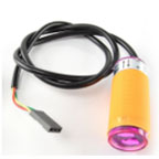
     

    Parts of the body were removed and replaced with thin trusses to help with the stability of the body.


    The printer supplied by Professor Hill was lacking around 0.5’’ to properly print the base and top in one go so I had to split the parts within Solidworks to 2 parts.


    The height of the sensors and emitters was set to that it was exactly at 3 inches (+/- 0.01inches due to the PLA shrinking and expanding from the print)


    The body was printed with a 25% fill density, x1.2 wall thickness (typically x0.8 and x1.2 and always a factor of 0.4), and at a speed of 40mm/s. The print time was barely affected when changed to 0.8 so I opted to add slightly more rigidity to the body this way.


    The body’s dimensions are essentially scaled down to the width of my Galaxy S4 phone (also held on by a ledge within the body) but it couldn’t have been an exact replica of the Goliath tank due to the print time requirement. There just wasn’t enough time to print all of the side panels and bolts while fitting the phone within the body of the rover.


    The total print time came out to around 5hr 57minutes.

    2


    3


    4


    Capture


    Conclusion

    The redesign has met all but one requirement partially (scaled model). The model has the general shape of the tank but is lacking the panels and bolts.


    Sources


    https://www.pololu.com/product/106