Spring 2020 Build-A-Block Arm Design and Material Research
/in Build A Block/by ParkerABy: Parker Anderson
ROBOT ARM RESEARCH AND COMPARISON
In class Professor Hill mentioned that it helped him to alter the words in his search and it helped him find more information on what he was looking for. We did exactly that and searched “3D printable robot arm”,”3D printable small robot arm”,”small robot arm”,”3D printable robot arm files”, and “printable robot arm”. We found that the printable robot arm search worked the best because most projects that are open for the public to 3D print are generally not going to be on the larger side. We found the best sizes for robot arms with this search from websites such as LittleArm, MeArm, Thingiverse, and Instructables.
| ARM LINK | MODEL | COST | JOINTS | MOTORS/SERVOS |
| #1 | 2C | $15.00 | 2 | High Geared Servos |
| #2 | Original | $8.00 | 2 | High Geared Servos |
| #3 | 0.4 | Free Files | 1 | 9G Micro Servos |
| #4 | Mini Arm | Free Files | 2 | 4 SG90 Servos |
| #5 | 6DOF | Free Files | 1 | 9G Micro Servos |
| #6 | OpenScad | Free Files | 1 | MG90 Micro Servos |
| #7 | RA80 | Free Files | 2 | Mabuchi RE-140 |
| #8 | 3D Print | Free Files | 2 | RadioShack Micro Servos |
Each of these sites were very helpful in showing the suggested servo or motor that they designed the arm to work with, however, many of the arms we looked at did not have dimensions. We believe the creator/designer did not include dimension limits in order to allow the customers to scale the Solidworks files to their desired size.
MATERIAL RESEARCH
Below is the tradeoff study was done for laser cutting materials. Build-A-Block was originally deciding between wood and acrylic for the final V3 design based on price and strength, however due to classes being canceled we stuck with the V2 design made of wood.
| MATERIAL | MAX THICKNESS | STRENGTH | LIMITATIONS |
| Woods | 1/4″ | Can depend on type, common is pine or birch | Woods can be resinous and catch fire, plywood contains glue and will not cut as well as solid wood, engineered woods may char when cut, overall avoid oily/resinous woods |
| Acrylic | 1/2″ | Strong depending on thickness | Cuts very well and stays solid |
| Magnetic Sheet | Strong | No problems with cutting | |
| Carbon Fiber | Strong | Must be cut at slow speed | |
| Corrugated Plastic | 1/4″ | Medium | Cutting causes vertical strips to fall away |
| Solid Styrene | 1/16″ | Medium/Low | Needs to be very thin |
| Mylar | 1/16″ | Medium/Low | Can bubble, curl, and warp during cutting |
ARM AND CLAW REDESIGN
After the V1 demo worked on how Build-A-Block was going to modify the arm that will attach to the top of the Goliath. First, we decided to make a template to start with for the attachment designs. We first started this by opening the Goliath SolidWorks files and isolating just the top panel of the tank.
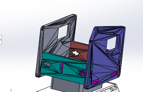
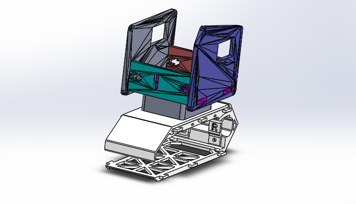
The next step was where we encountered a problem, we opened up the downloaded arm .stl files in SolidWorks but the program could not convert them correctly. This created a problem because each part of the arm now had a number of random surfaces resulting in each part not being a solid body. Below is an example of the converted base pieces of our arm.
We kept pushing forward with this design until we could figure out how to fix these combined surfaces that were created on each part of the arm. As we kept going with the design we learned how to use the “mate” tool to attach these pieces in the 3D space. Once everything was “mated” together this became the result, our template for different arm attachment designs.
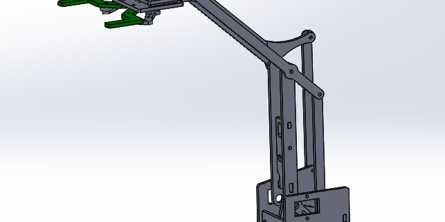
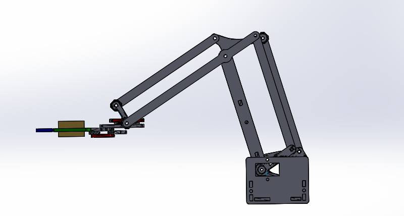
After designing this template we moved onto the next task, which was to lengthen the arm parts so we could have our robot reach further than a Jenga tower. After rebuilding each of the arm parts we had to check a few things off our to-do list: redesign the claw to pick up the Jenga block lengthways, lengthen the arm components evenly, and make sure it was tall enough to reach up to the top of a Jenga tower. Below is the final product for our post-V1 design.
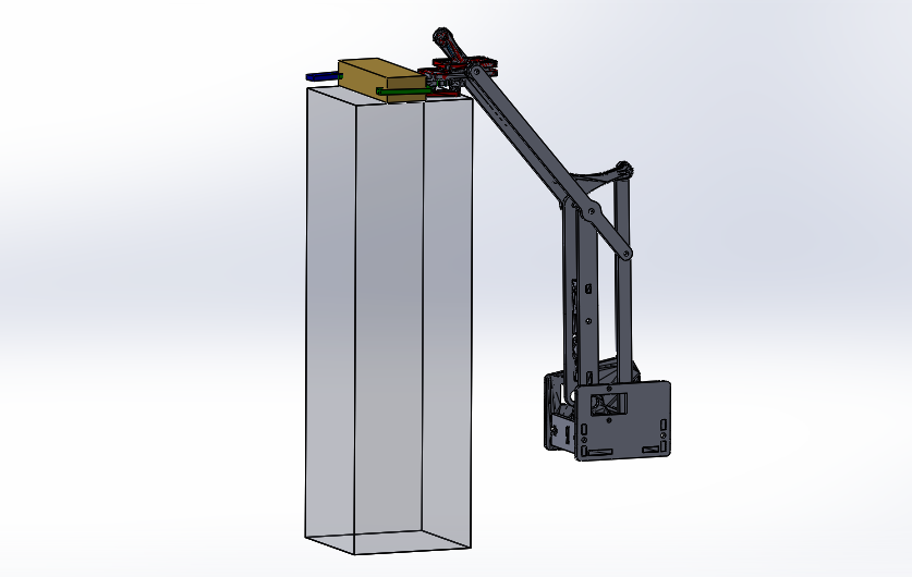
We built a “Jenga block” and “Jenga tower” in SolidWorks to ensure the claw was grabbing and sitting correctly within the model, as well as able to reach the necessary height to play the game of Jenga. Both the block and tower dimensions were modeled based on the company Hasbro. The height of the Goliath base was also taken into account, hence why the robotic arm appears to be floating in the images. Below are some different angles of the model gripping the Jenga block next to the Jenga Tower.
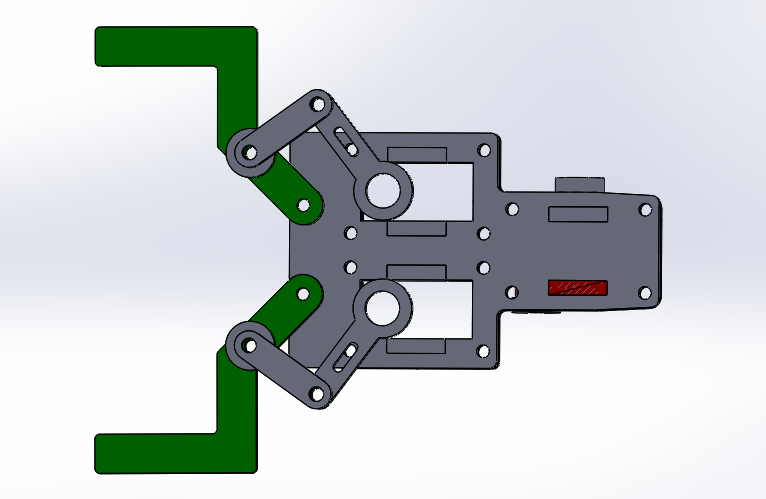
Next, we decided to take the design further but implementing another servo into the claw design. By altering the claw to be controlled by two servos we could ensure that each side of the claw could open and close to adjust as necessary when reaching to pick up a Jenga block. We had to weight the options, as we would have more control over the arm, but also more weight added, thus needing more torque. After considering the options and looking back at the torque calculations we decided that we could safely alter the design to add in the second servo. Below is the Solidworks diagram of the new claw design, with the rectangle cut-outs to show where the MG90 servos will go.
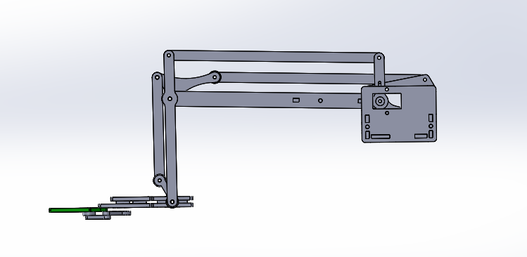
For our V3 arm, we realized there was so much motion being wasted when the claw was reaching its lowest point. For our purposes, we really only need the claw to reach the table surface that the Goliath is rolling on. So we decided to resize our bicep section of our arm so it is longer, and whatever extension length came from that, we took from the forearm section. Screenshots below.
Figure 7. Angled view of V3 arm.
Figure 8. Side view of V3 arm.

